» Electronics » Power supplies »Charger for 18650 from trash

Charger for 18650 from trash


Assembled into one design several simple circuits and blocks.
The scheme is very simple and soldering it will not be difficult even for a novice soldering iron

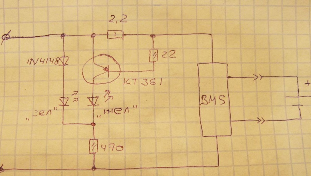
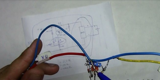
Three resistors, transistor, diode, two-color LED. We solder by hinged installation.
Details can be obtained almost everywhere. BMS from any battery, the rest from old Soviet technology.

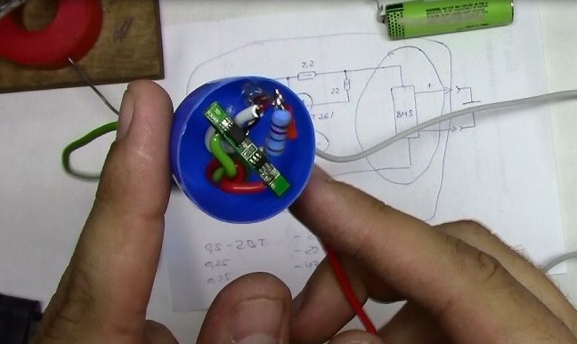
Solder the BMS scarf to our circuit. We mount in the egg from the kinder. Glue with thermal glue.

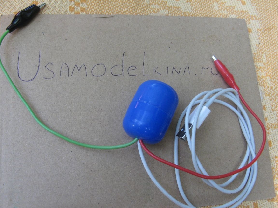
The wires are brought out. We mount crocodiles and the device is ready.

The LED indicates the charging process. Yellow - the charge is on. Green - charge is over

Detailed assembly instructions are displayed on the video.
7.3
6
6

Add a comment

    • smilesmilesxaxaokdontknowyahoonea
      bossscratchfoolyesyes-yesaggressivesecret
      sorrydancedance2dance3pardonhelpdrinks
      stopfriendsgoodgoodgoodwhistleswoontongue
      smokeclappingcraydeclarederisivedon-t_mentiondownload
      heatirefullaugh1mdameetingmoskingnegative
      not_ipopcornpunishreadscarescaressearch
      tauntthank_youthisto_clueumnikacuteagree
      badbeeeblack_eyeblum3blushboastboredom
      censoredpleasantrysecret2threatenvictoryyusun_bespectacled
      shokrespektlolprevedwelcomekrutoyya_za
      ya_dobryihelperne_huliganne_othodifludbanclose
72 commentary
Quote: popvovka
Thanks for the link!
If this is really interesting for you, then please:.
If you read the source in scrap, then in Russian a good explanation,.
Author
Thanks for the link!
Oh, pounced, what do I have to do with it?
I am not an author.
3 watts resistor, resistance erased.
I do not have to report to you. Want a photo, send a camera. On my phone it removes how it removes.
It works and okay, in my village this charger will work.
Quote: popvovka
For fun, where to read about bms
Where? The Internet is full of normal information. If you don’t find it yourself, ask, I will tell you where to get it. )))
Quote: popvovka
my achievements have caused you to undermine interest.
You have megalomania, because in China
Quote: popvovka
Indication circuit borrowed from Chinese charging.
You pass it off as yours, and consider a seven-part diagram with seven errors to be “cool”.
Quote: popvovka
And ready-made modules are not an option, many packages are lost. Yes, and the delivery price bends up. Previously, the board cost 20p, and now 60-70r. Expensive for experimentation.
If it’s expensive for you to spend 70 rubles and ensure normal long-term operation of the battery for 500 rubles, and banging this product, and then undercharging and ruining the batteries is normal, then I stop making further attempts.
For those who can read, I said everything.
Author
Quote: axivovka
3 watts of another, with such resistance did not find.

Apparently from work I did not see what was edited) And I realized that 3 watts, but the resistance xs what, the time will tell.
For fun, where to read about bms, otherwise my achievements have caused you to undermine interest. I charge for the repeated use of this technique. I use in toys and exclusively 18650, but the circuit without indication. I want to buy everything abruptly, but xs how not to run into the trash. I wrote to a person, maybe she will answer about charging.
And ready-made modules are not an option, many packages are lost. Yes, and the delivery price bends up. Previously, the board cost 20p, and now 60-70r. Expensive for experimentation.
Thanks for the comments.
Quote: popvovka
And where did he write about 3 ohms?
Again. ((
Quote: axivovka
Collected. Works. The resistor was slightly hot)) I put a stronger pevku
Not a word about changing the circuit, therefore, collected on it. Then he stated that he had put a 3 W resistor. In the circuit there is only 1 powerful resistor - 2.2 ohms. But such things do not happen in nature, PEV-3 starts with 3 Ohms! Therefore, there is no photograph.
So nothing was collected.
Author
Found a line. And where did he write about 3 ohms?
It seems they are talking about some other denomination, or am I mistaken?
A person will unsubscribe, we will find out his opinion.
Quote: popvovka
Where and who is deceiving did not understand.

Here is where:
Quote: axivovka
Put more powerful pevku

Quote: Ivan_Pokhmelev
What power set?

Quote: axivovka
3 watts, I did not find another with such resistance.

Quote: Ivan_Pokhmelev
Please take a picture of such a rare resistor, only so that the face value and year of manufacture can be seen.


And that’s it! There is no photo, because there is no PEV-3 with a value of less than 3 Ohms! You can’t even fool correctly!
Author
It became already interesting))
Where and who is deceiving did not understand.
The man became interested. Collected. Works. Now you accuse him of deceit.
Hmm ...

axivovka And what kind of Robiton are you talking about, is there a link to the product?
Unsubscribed to you in PM with a question.
Quote: axivovka
With your questions, you remind me of a math teacher)))
And I will not say whom you remind me of. Understand again, everything here I’m writing is not for you, but for beginner hams, so that they don’t decide to repeat this “cool” product.
Quote: axivovka
The board I think is standard micro equipped.
If standard DW01, then the cut-off voltage is 4.3 V ± 50 mV. Perhaps your device is not very accurate and showed 4.18 V, but in fact there was more.
Quote: axivovka
3 watts of another, with such resistance did not find.

Exactly, there was nothing to deceive! There is no PEV-3 rated less than 3 ohms!
And the rest that you wrote under this nickname is just as there is no faith. Just because it cannot be. Unless, of course, you have an abnormal zone where the laws of physics do not apply. The most favorable case for you is to say that the devices are faulty.
"Execute, no mercy"
3 watts of another, with such resistance did not find.
The board I think is standard micro equipped. It is poured into the rubber compound, from the phone of an old Samsung.
The idea is your name is not Ivan Andreevich? With your questions, you remind me of a math teacher)))
Quote: axivovka
3 watts, I did not find another with such resistance.

Please take a picture of such a rare resistor, only so that the face value and year of manufacture can be seen. ;)
Quote: axivovka
The board fought off and the voltage was about 4.2 volts.

What kind of chip is in the applied BMS?
What makes you think that I’ll kill the battery? The board fought off and the voltage was about 4.2 volts. When installing the Roboton master charger on charging, the battery scored only 10mAh.
Ohm's laws are there, but nobody canceled the experiment.
3 watts, I did not find another with such resistance.
Quote: axivovka
Put more powerful pevku
What power set?
Quote: axivovka
y (well, here I picked up on the experiment).
Why an experiment? Physics, 7th grade, Ohm's law - that's all.
Quote: axivovka
there are cons, but the price ...
Price - dead battery, constantly rechargeable during operation. What prevents to buy a scarf on TP4056? The price is 60-80 rubles.
Collected. Works. The resistor was slightly hot)) I put a stronger pevku (well, here I picked it up by experiment). The current pleased, my battery will not die. Very simple, there are also disadvantages, but the price ...
Scheme slightly tweaked. Commendable, but why is it so inconsistent and small? Is it really so difficult to calculate that the current-sensing resistor should be two-watt? Is it really difficult to calculate, at least approximately, the value of the base resistor?
Quote: popvovka
Typo, current 0.1 amperes.
Again does not converge. ((Explain how this could be?
Author
Quote: popvovka
Charging current 1 A.

Typo, current 0.1 amperes.
Quote: popvovka
Charging current 1 A.
5 V - 3.55 V = 1.45 V. 1.45 V / 2.2 Ohms = 0.65 A. Where does 1 A come from?
Or your devices are malfunctioning, or the circuitry is incorrect, or Ohm’s law is some kind of own.
What chip is in the BMS of your charger?
And even if there is a very successful instance with a cut-off voltage of 4.2 V, there is still no recharge mode with a decreasing current at a constant voltage. This scheme cannot be recommended for repetition! It is impossible!
Author
Conducted repeated measurements.
Charging current 1 A.
Element bu 18650 with a residual capacity of 2050mAh.
At the time of the end of the charge, the voltage on the cell was - 4.18 volts. The voltage at the beginning of the charge was 3.55 volts.
Let theorists say that bullshit, but practice speaks for itself. IMHO.
Quote: Valery
It is rather "if there is no sensible charger at hand, then this is possible" ...))))))

Not certainly in that way. “If there is absolutely nothing, but urgently needs to be somehow charged,” then it will do. For regular use categorically is not suitable, as it leads to accelerated battery degradation, and it charges slowly and not completely.
Author
For the price of course, cool from the trash. I have such a concept. But since people ask, I’ll change the name.
There are many analogues of your charge, with a friend of Liitokala Lii - 500. I have IMax at work, it’s simple at home. I’ve been translating into lithium for several years now, without any problems. Now China has been going to Crimea for a long time, cheap scarves are over. So I apply the applicable.
IMax once ordered, but sold, it was very requested.
Thanks for the comments.
But seriously, I don’t like this word at all - "cool." I believe that in relation to homemade products it can only be applied THEN if the homemade product exceeds the serial models in terms of parameters, or has some useful parameter that is not in serial ones.
For example, I use these:
There is nothing special about them, but I liked the ease of use and functionality ... And especially because they’re not afraid of installing the “wrong batteries” or the “wrong side” than my women sometimes sin ... Therefore, I bought a few more such that they were everywhere at hand, and very pleased ...
... Tell me, author, what is your "cooler"?
Author
Yes, he is, as always, in his own style. xaxa
In short, the essence of your dispute is as follows: The charger is by no means “cool” (Tell me, why is it cooler than the same IMax?))). It is rather "if there is no sensible charger at hand, then this is possible" ...))))))
... That's right, Hangovers?)))))
Quote: Ivan_Pokhmelev
The most common BMS, on the DW10,.
Typo. ((DW01, of course.
For example, in the S-8200A series, the overvoltage protection tripping voltages are as follows: http://dropmefiles.com/va3Su
Quote: popvovka
BMS with a final charge of 4.35 volts are extremely rare, I have not even come across.

BMS has no "final charge". BMS is protection. The most common BMS, on the DW10, have a trigger voltage of 4.3 ± 50 mV, that is, (4.25 ... 4.35) V. There are other microcircuits for other voltages. A protection voltage increased by 100 mV is chosen so that it does not interfere with the full charge of the battery.
Quote: popvovka
I watched today for fun how it charges IMax. Starts at 3.2 volts, ends at 4.2 volts. The charge current from 3.2 volts is set (I had 1 ampere), at the end of the charge it fell, as it should be. Since the first stage is a constant current charge, and the second stage is a constant voltage charge, at which the current drops. But the initial stage was still with a lot of current.
This is the standard mode. Charging is just beginning, of course, not from specifically 3.2 V, but from the residual voltage of a discharged battery.
Quote: axivovka
But I did not see about 4.35 from the author.

And this
Quote: popvovka
Elements with a voltage of 4.35 volts are specific

who wrote? Am I what?
Author
Exactly, I just mentioned, and immediately reproached me.
BMS with a final charge of 4.35 volts are extremely rare, I have not even come across.
I watched today for fun how it charges IMax. Starts at 3.2 volts, ends at 4.2 volts. The charge current from 3.2 volts is set (I had 1 ampere), at the end of the charge it fell, as it should be. Since the first stage is a constant current charge, and the second stage is a constant voltage charge, at which the current drops. But the initial stage was still with a lot of current.
Clear)
But I did not see about 4.35 from the author. Just a mention of what this may be rare. And it is applied as I understand it, ordinary and common.
I don’t understand how to quote.
Either select what you want to quote and click "Quote", or copy what you want to quote, paste, select again and click the "Insert quote" button (the third one on the right - quotation marks are drawn).
Quote: axivovka
But you tried to apply a voltage limit of 4.3 V for ordinary 18650.

This is not me, but the author applied.
Shorter confused by their comments.
I will try again.))
Author made external Charger. The correct charger should work for lithium-ion and lithium-polymer batteries in almost the same way:
1. If the battery is discharged below (2.9 ... 3) V, it is necessary to charge about 10% of the rated current with a small current. The specific level depends on the battery, but the average values ​​are.
2. After reaching the above level, it is charged with a nominal charging current, the typical value of which (0.5 ... 0.7) C. That is, if the battery capacity is 2000 mAh, then the current should be (1 ... 1.4) A.
3. After reaching the battery (4.1 ... 4.2) V (depending on the manufacturer's recommendations), charging is carried out at a constant voltage. The current drops as it charges until the battery is fully charged. The moment of completion of the charge occurs when the charge current decreases to 3% of the initial value.

How does the presented device work:
1. The initial current is (U of the power supply - U-battery) / R current. If the battery is discharged to 3 V, then (5-3) / 2.2 = 0.9 A.
2. As it charges, the current drops to (5-4.3) / 2.2 = 0.3 A.
3. When the voltage reaches 4.3 V, the battery is turned off.

What are the disadvantages of this algorithm? The main thing is that the charge occurs to too much voltage. 4.3 V is too much, it is protection against battery destruction. For a maximum charge while maintaining the operational properties, no more than 4.2 V is needed, for extending the service life (but with a decrease in the maximum charge by 10%), 4.1 V. At a voltage above 4.2 V, chemical processes begin leading to battery degradation . Built-in battery protection at 4.3 V is designed to prevent destruction of the element, and not to ensure proper charging.
One more important point should also be taken into account: nothing is absolutely exact in technology; there are certain tolerances for everything. So for the operating voltage BMS there is a tolerance, for the common DW01 it is ± 50 mV. In addition to this IC, there are others whose response thresholds are, depending on the type, from 4.1 V to 4.35 V with tolerances of up to ± 100 mV.

Correct charging is most easily achieved using the "folk" scheme on TP4056.
What should I look for here? If TP4056 is built into the device, then the battery, of course, must be protected by BMS. It can be either built-in to the battery or located on the charging module with the TP4056. If charging externalthen BMS on charge not needed.

In mobile phones, the correct charge algorithm is provided by the phone controller, not the protective board.
Wait, I don’t keep up with your train of thought.
I don’t understand how to quote.
But you tried to apply a voltage limit of 4.3 V for ordinary 18650.
And where it is said about it, flipped through correspondence and did not find. The handkerchief from the mobile is not at 4.35.
Shorter confused by their comments. There was a topic, everything is clear. But they wrote so many comments that the ordinary person no longer understood (Thank you for confusing!
I remember Drugan used handkerchiefs from mobiles and soldered them to laptops many years ago and everything worked and works. And then there were no elements with increased voltage.
Quote: popvovka
There are recommendations in the IMax operation algorithm.
What is this algorithm?
Quote: popvovka
Li-ion and Li-pol can be charged, work in one common mode.
Did I say that this is not so?
Quote: popvovka
Elements with a voltage of 4.35 volts are specific and are rarely used, mainly in laptops, to increase the operating time.
But you tried to apply a voltage limit of 4.3 V for ordinary 18650.
Quote: popvovka
What is that 2.9 volts to which it charges?
With a strong battery discharge: because DW01 allows you to discharge up to 2.4 V, you must first charge up to (2.9 ... 3) V with a small current, and not immediately cut the total current.
Quote: popvovka
4056 (do not pretend that you do not know about such a shortened form when it comes to charging akb).
I did not understand you, I thought that “c” refers to the name of the microcircuit.
Quote: popvovka
4056 ... useless alone and applying it with DW01 and 8205.
Not at all!
You have an external charger, in it DW01 and 8205 are not needed. Explain why they are there?
Quote: popvovka
And blaming a person for complete incompetence is rudeness!
This is not rudeness, but, unfortunately, a statement of fact: you do not understand how to charge the battery correctly, you do not know how TP4056 and the bundle DW01-8205 work. ((
Author
I do not agree. There are recommendations in the IMax operation algorithm.
Li-ion and Li-pol can be charged, work in one common mode. Practice proves the logic of these programs. Even Li-hv can be driven in Li-ion mode, but the measured capacity will not be correct.
Elements with a voltage of 4.35 volts are specific and are rarely used, mainly in laptops, to increase the operating time.
In the usual case, it is possible to use BMS the same for Li-ion and Li-pol. Since the final voltage for two chemistry is not critical. Practice shows confirmation. Otherwise, the point here is to write to me like that.
2. Charging with a current of 1/10 from the programmed resistor Rprog (100mA at Rprog = 1.2k) to the level of 2.9 V (if required);
What is that 2.9 volts to which it charges?
4056 (do not pretend that you do not know about such a shortened view when it comes to charging the battery) is useless alone and applying it with DW01 and 8205.
And blaming a person for complete incompetence is rudeness!
I do not want to communicate with you, for such an appeal!
Addition to the above.
DW01, 8205 can be installed additionally in cases where TP4056 (or its analogue) is installed in the device itself with a battery without BMS.
Quote: popvovka
Just the boards in their majority charge up to 4.2 volts, so the kat is installed on Li-pol, with the exception of the elements Li-hv 4.35 volts.
That is, you agree that your option is not optimal and leads to a decrease in battery life.

Quote: popvovka
TP4056 does not provide protection against overdischarge, short circuit, overcharge. For all this, in China there are boards with 4056, DW01, 8205 (I think you understand what I mean).
Again - complete incompetence. ((
TP4056 just provides protection against overcharge, it is designed for this. Here is her algorithm:
The charging process consists of several stages:
1. Monitoring the voltage of the connected battery (constantly);
2. Charging with a current of 1/10 from the programmed resistor Rprog (100mA at Rprog = 1.2k) to the level of 2.9 V (if required);
3. Charging with a maximum current (1000mA at Rprog = 1.2k);
4. When the battery reaches 4.2 V, the voltage stabilizes at 4.2 V. Current drops as it charges;
5. When the current reaches 1/10 of the Rprog programmed by the resistor (100mA with Rprog = 1.2k), the charger is turned off. Go to step 1.

TP4056, of course, does not provide protection against overdischarge, it does not need it, because it is designed for charge Battery.

What is "from 4056" I do not know, please give a link. DW01, 8205 are intended for installation in BMS and are not suitable for proper charging without a circuit similar in function to TP4056. They can be installed additionally, which is sometimes done, but they themselves cannot provide correct and safe charging.
Author
Thank you for your interest in the article.
But.
Just the boards in their majority charge up to 4.2 volts, so the kat is installed on Li-pol, with the exception of the elements Li-hv 4.35 volts.
A voltage of 4.1 volts is applicable for Li-ion. So says IMax and I believe him and not only him.
TP4056 does not provide protection against overdischarge, short circuit, overcharge. For all this, in China there are boards with 4056, DW01, 8205 (I think you understand what I mean).
Quote: axivovka
I think in any case, the board will not do worse.

But it will not be able to provide normal long-term operation. There are a lot of "holes" in this product:
1. The worst thing is that the charge occurs until the voltage is too high. 4.3 V is too much, it is protection against battery destruction. For maximum charge while maintaining operational properties, no more than 4.2 V is needed, for extending the service life (but with a decrease in maximum charge by 10%), 4.1 V.
2. The charge current at a voltage of 5 V power supply varies from 0.9 A at 3 V to 0.3 A at 4.3 V on the battery, that is, charging takes a long time.
3. A small charge current is not provided with a strongly discharged (less than 3 V) battery.
4. The maximum battery charge is not provided.
5. The yellow and green LEDs are mixed in the diagram.
6. The power of the pickup resistor is incorrect.
7. Wrong base resistor rating.

A simple scheme on TP4056 does everything right and quickly, in contrast to this "cool".
Yea Yea. But the board protects against discharges below normal, charge above normal, short circuit (accident).
I think in any case, the board will not do worse. For example, 18650 with actual capacities, even from 1800mach. And this charger simply will not put them, we will write everything to the loss in wires, components and the honesty of Chinese charges. And then they write 2 amperes, but in fact there is no ampere either. On sale such "budget" is full.
Quote: popvovka
Is the BMS board for fun in the battery all built in?

This fee is for emergency shutdowns. Its parameters do not provide any of the parameters of work in the nominal mode!
Quote: axivovka
As far as I remember, there is protection against sudden overcurrent.

Common motherboards on DW01 have protection against sudden overcurrent and short circuit. But both at discharge, not when charging the battery.
I think that means bms will not allow ditching an element. As far as I remember, there is protection against sudden overcurrent.
And if there is your article on these boards, I would have read it, otherwise snippets of comments are not perceived.
Quote: popvovka
Actually, we are talking about the BMS board.
Exactly. Here are your words:
Quote: popvovka
The current will not exceed, for this there is a BMS board.
But you, unfortunately, do not know what the BMS card is for, which is installed in telephone batteries.And it is designed to protect against overcharge and overdischarge by turning off the battery when the voltage on it exceeds the established boundaries. From exceeding the charge current it does not protect. In your device, the current is limited by a 2.2 Ohm resistor, the power of which you indicated is much less than necessary.
Why is such low power indicated for a current limiting resistor?
And another question: why pump such a huge current into the transistor base?

We advise you to read:

Hand it for the smartphone ...