
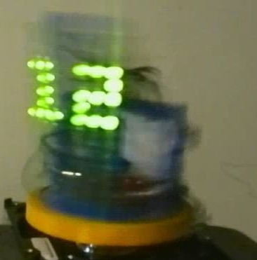


If you want to really do something amazing with which you can brag to your friends, collect such a 3D clock. However, this may not necessarily be a watch, because in electronics You can lay out the display of almost any image. Here, the controller is used as the “thought center” Arduino. It is he who decides exactly when and what kind of LEDs should be lit so that the numbers appear.
But everything works very simply, LEDs are mounted on a rotating stand, which are turned on in a special way. The engine spins this stand from the computer's hard drive. The information received is processed by our brain, and we see an image “hanging in space”. If it were not for the hum of the engine, this picture could be presented as a hologram.
According to the author, most of the necessary details for homemade can be found in old electronics.
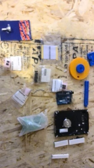
Materials and tools for homemade:
- Arduino Uno controller;
- 6-15 LEDs;
- wires;
- 9V power supply;
- white tape (for QTI sensor);
- QTI Sensor (you can buy);
- An old hard drive with a working engine;
- support;
- power supply for the hard drive;
- Velcro
- 3D printer access and simulation software.
However, a 3D printer is not necessary for home-made, everything can be made of wood or plastic, just the printer makes it much easier.

Homemade manufacturing process:
How it works
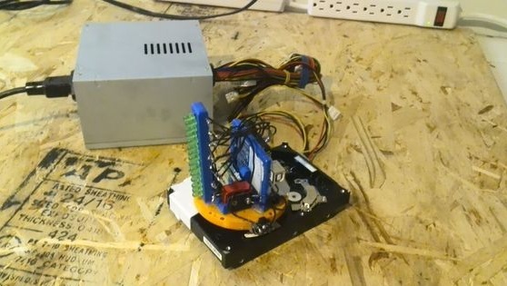
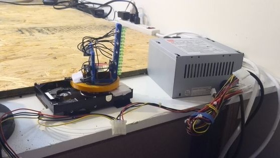
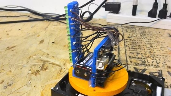
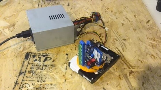
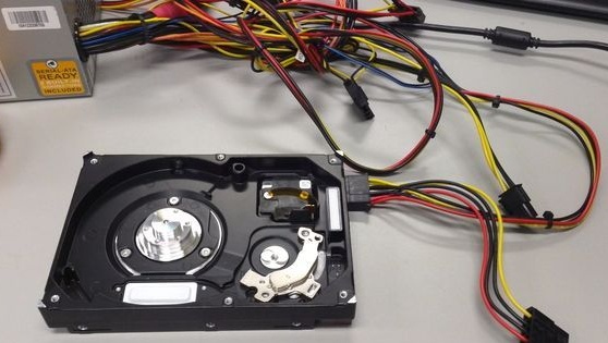
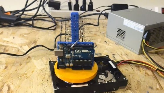
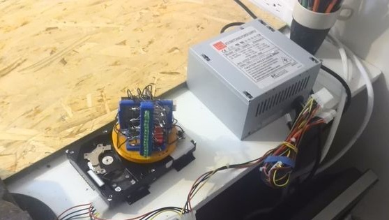
To connect a hard drive, you will need a power supply from the computer. A piece of white tape is attached to the corner of the hard drive. Arduino controller, sensor, and LEDs are mounted on a rotating stand. The sensor is used in color; it is connected in parallel with a white ribbon. When the engine rotates, the sensor passes the white tape and the controller instructs the LEDs to turn on, as a result, the current time flashes.
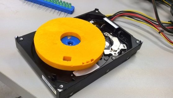
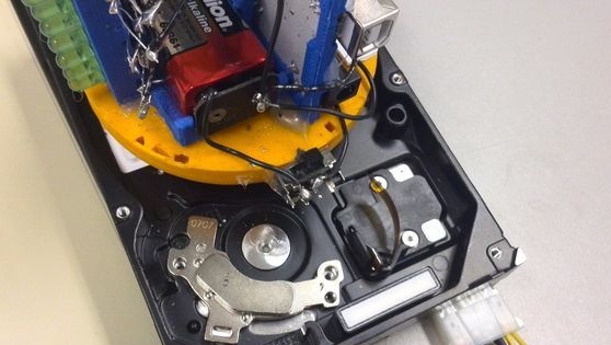
Step one. Disassemble the hard drive
First of all, you need to disassemble the hard drive, for this you need to unscrew a few screws. Sometimes it’s not so simple, because the screws are made for a special screwdriver, and they are tightened quite strongly. You need to remove the top cover, as a result, access to the engine should appear.
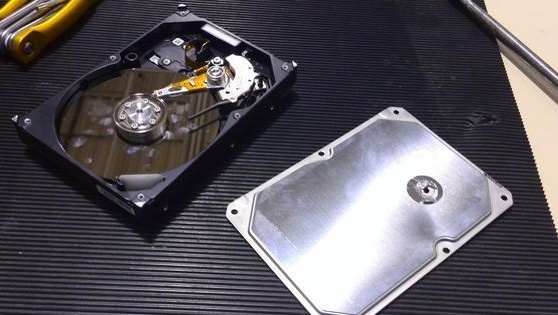
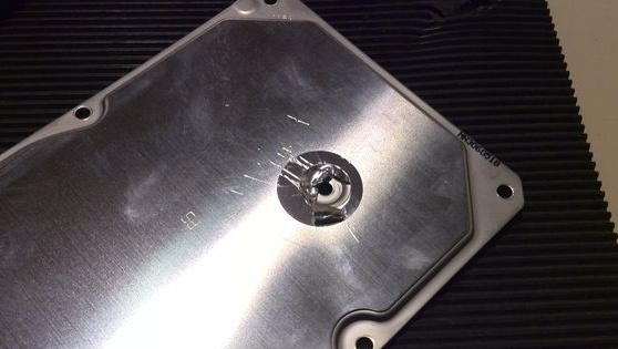
From the hard drive you need to remove everything that is unnecessary, including the hard drive itself. Only the motor shaft and power board should remain.


Now there’s another nuance, the engine needs to be connected, many do not know how to do this, because the motor is multiphase and will not work on the board without a generator.First, you need to connect power to the HDD from the power supply, but it will not turn on at the same time. To make it work, you need to connect the green wire to the black.
Step Two Making the base for mounting electronics
The author made the basis with the help of a 3D printer. As a result, everything comes out quickly, accurately and beautifully. But all this can be done with other materials, the most important thing is that the design reliably holds the electronics, otherwise it will fly apart in different directions when the motor is turned on.
In total, the framework consists of five elements:
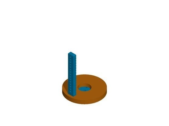
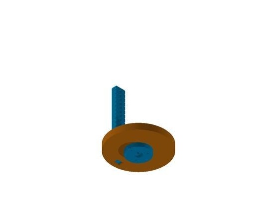
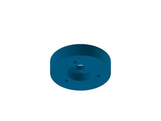
Base
All electronics will be on this part. The base has a hole in which the LED tower is inserted. There is also a battery pack and Arduino holder, they are glued. At the bottom of the center there is a connecting ring to which the connecting part fits.
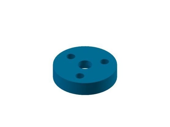
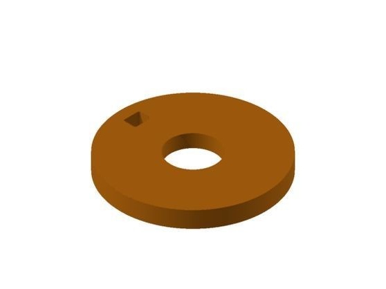
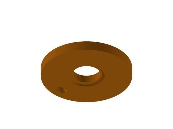
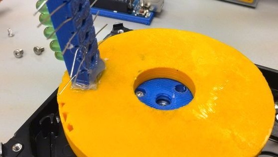
Connecting piece
There are three holes in this part, with the help of which they are fastened to the hard drive hub. The base rests on it.
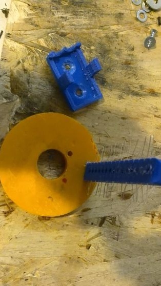
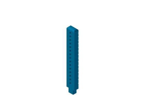
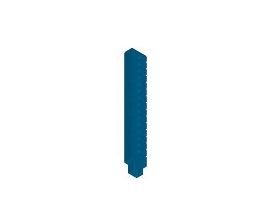
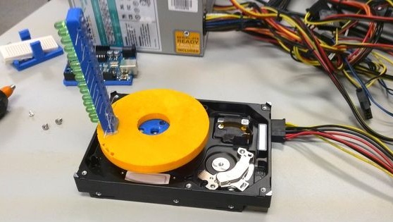
LED Tower
This element holds the LEDs. In total, they need 5 pieces, but if necessary, you can install 15.
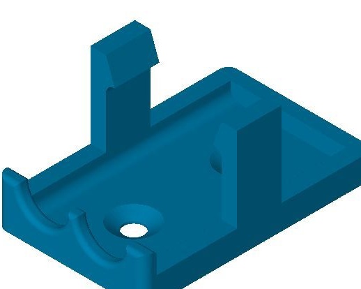
Arduino Holder (optional)
This item can be purchased if necessary.
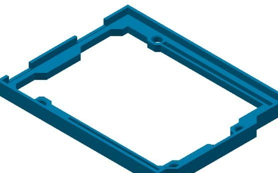
Battery holder (optional)
This item can be bought.
If you decide to print the details on the printer, then for these purposes the necessary STL and ipt files are attached.
Due to the fact that hard drives are different, the author’s part may not be suitable for mounting. In this regard, the editor will need to change the files, making the mount specifically for your hard drive.
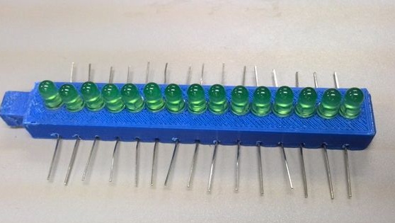
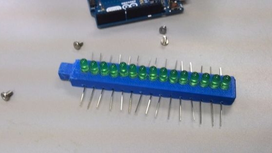
Step Three Install the LEDs
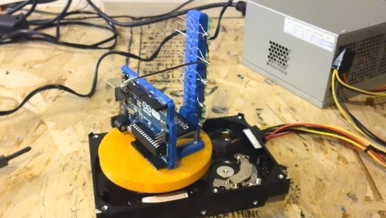
LEDs are mounted on an LED tower. For homemade work you will need 5 LEDs, this is specifically for the watch. All the positive contacts of the LEDs are placed in one row, as are the negative ones.
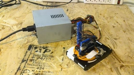
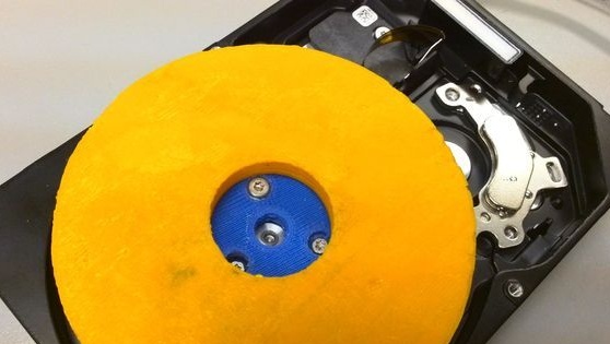
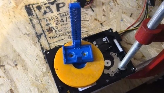
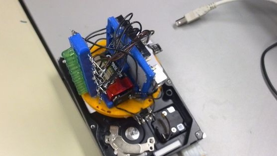
Step Four Putting the foundation together
The connecting part is attached to the engine hub with screws. LED tower is inserted into the base. The connection is fixed with glue. The base is mounted on the connecting part and also sits on glue.

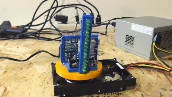
Step Five Arduino Battery and Controller Holder
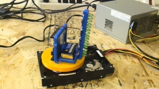
Holders are mounted on the base. The author fastens them with glue. Further, when the glue dries, you can install the Arduino controller and the 9V battery in their places.
Step Six Connecting LEDs to the minus
All the negative contacts of the LEDs need to be connected with one wire, and then this wire is connected to ground on the Arduino controller.
A switch is also installed on the base with glue.
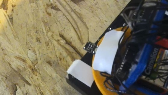
Next, do not forget to install the QTI sensor on the base. It should be pointing down. A tape should be parallel to the sensor, approximately 1 inch long.
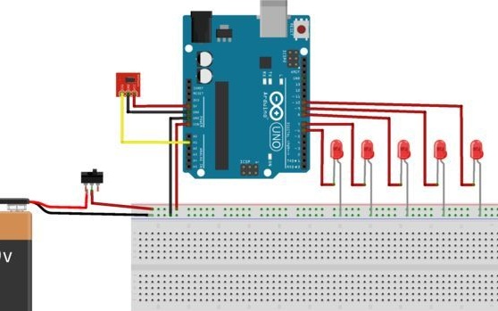
Seventh step. How to connect all the electronics
Step Eight. Set the clock using a code
The Arduino controller lights up the LEDs when the sensor passes near the white ribbon. We know that the QTI sensor hangs over a white ribbon because it returns a certain range of values. These values will be different for all POV hours. Therefore, your task is to find this threshold for your watch and drive it into the Arduino code.
To do this, download sensorTest.ino to your controller. Open the serial monitor by placing the QTI over the white ribbon. The serial monitor prints a range of values. The most common value to write down
For the author’s watch, the serial monitor usually printed out a value of 100.
Next, open hddClockTime2.ino. Scroll down to // EDIT THIS LINE.
Adjust the threshold until it is comfortable. Since the author had a total value of 100, he guaranteed that his condition would be true if ls1 is less than 110 and greater than 90. We need this condition to be true if the QTI sensor passes over a white ribbon.
The final stage. Check the watch
To check, you need to download hddClockTime2.ino, turning on the power of the controller and the power of the hard drive. The clock should show the current time. If the time is wrong, it can be changed in the code.
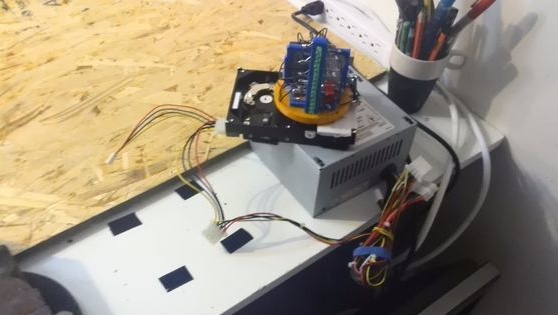
Due to the fact that the homemade product will create strong vibrations, the hard drive needs to be well secured. The author secured it statically with the help of corners and cogs.
In the future, the author plans to install already 15 LEDs, thereby expanding their capabilities. It is planned to make the watch work in 24-hour mode, rather than 12 (AM and PM).
All the necessary files for creating a watch can be downloaded here: