Hello website visitors
While browsing various sites, I found a very useful home-made product for home security, on the system Arduino.
Its author wanted to make a homemade product so that it was cheap and wireless.
This homemade product uses a PIR motion sensor, and information is transmitted using the RF module.
The author wanted to use an infrared module, but since it has a limited range, and the plus can work only on the line of sight of the receiver, so he chose the RF module, with which you can achieve a range of approximately 100 meters.
In order to make it more convenient for visitors to view the alarm assembly, I decided to divide the article into 5 stages:
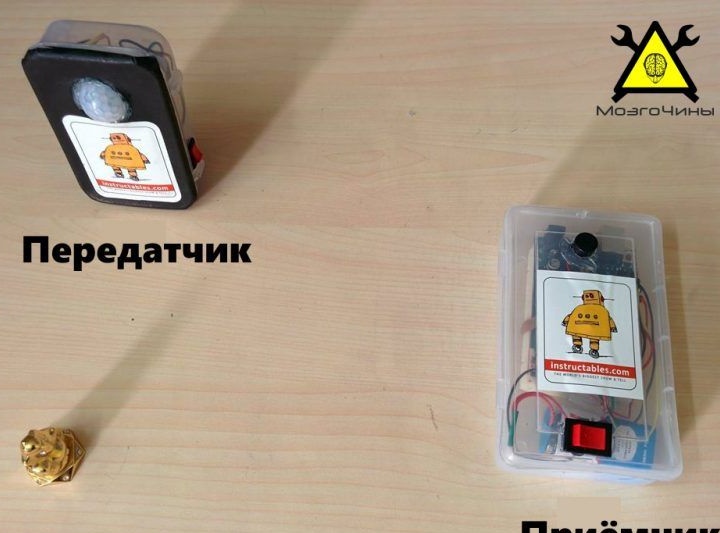
Step 1: Create a Transmitter.
Stage 2: Create a receiver.
Step 3: Install the software.
Stage 4: Testing the assembled modules.
Stage 5: Assembling the housing and installing the module in it.
So, let's start with the author’s video.
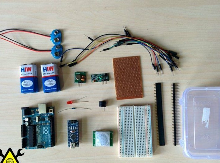
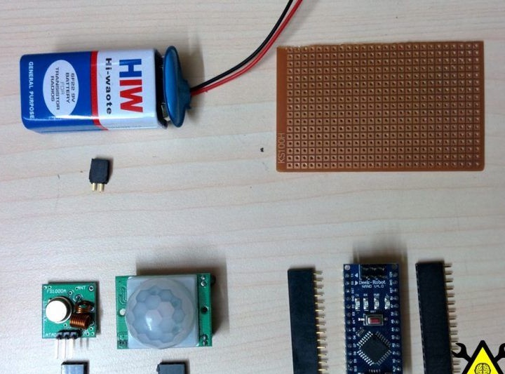
All that the author needed was:
- 2 boards ARDUINO UNO / ARDUINO MINI / ARDUINO NANO for the receiver and transmitter;
- RF transceiver module (433 MHZ);
- PIR motion sensor;
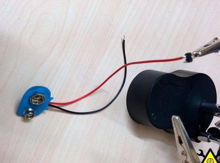
- 9V batteries (2 pieces) and connectors to them;
- buzzer;
- Light-emitting diode;
- A resistor with a resistance of 220 ohms;
- Bread board;
- Jumpers / wires / jumpers;
- Circuit board;
- Board to pin connectors;
- switches;
- Housings for receiver and transmitter;
- Colored paper;
- Mounting tape;
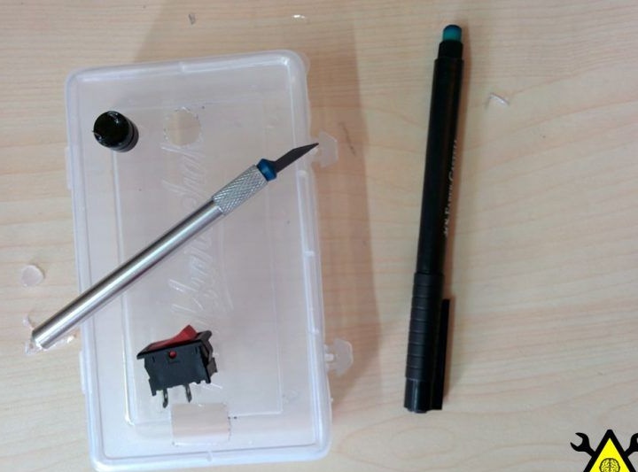
- Stacked scalpel;
- Hot glue gun;
- Soldering iron;
- Nippers / stripping tool;
- Scissors for metal.
We begin the creation of the transmitter.
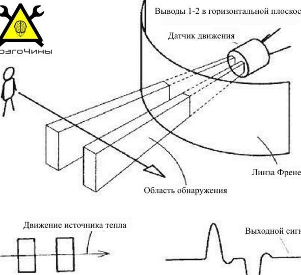
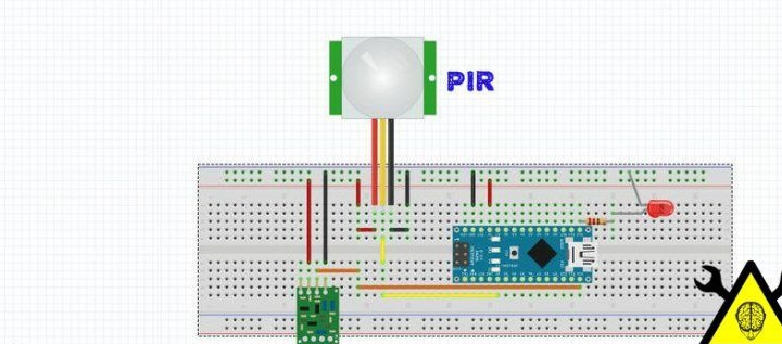
Below is a diagram of the motion sensor.
The transmitter itself consists of:
- motion sensor;
- Arduino boards;
- Transmitter module.
The author used the Arduino Nano as a control board.
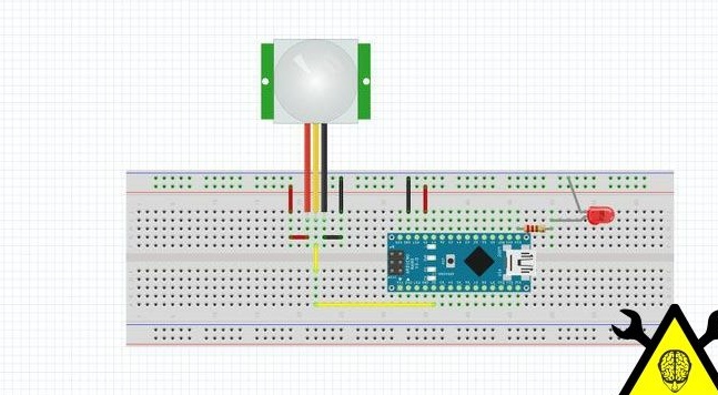
The author collected according to this scheme:
The sensor itself has three outputs:
- VCC;
- GND;
- OUT.
Then the author connected the conclusions of the sensor with the conclusions of the Arduino board:
- Vcc> 5v;
- GND> GND;
- Out> D2.
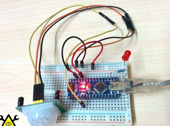
After which, I checked the sensor
Before downloading the firmware, the author makes sure that the current board and serial port are correctly installed in the Arduino IDE settings. After which I downloaded the sketch:
View online file:
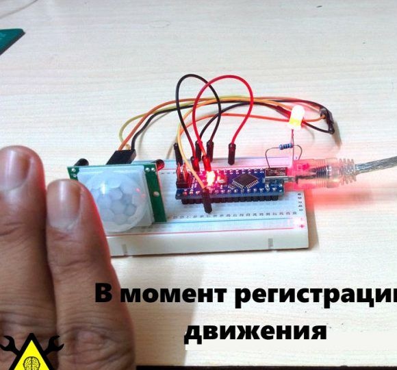
Later, as the motion sensor detects movement in front of you, the LED will light up, and you can also see the corresponding message in the monitor.
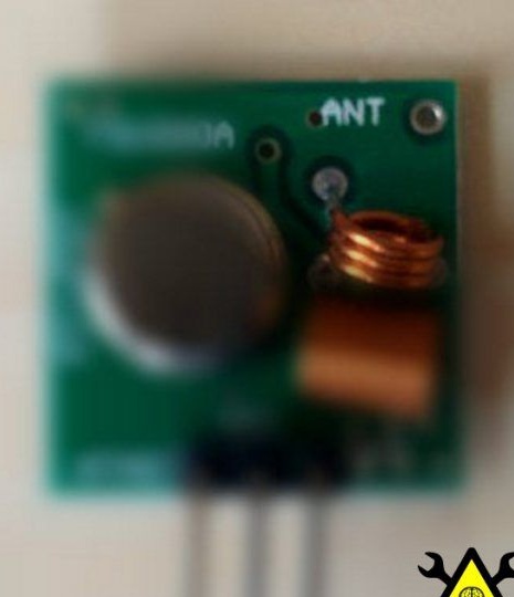
Next, the author connects the RF Transmitter.
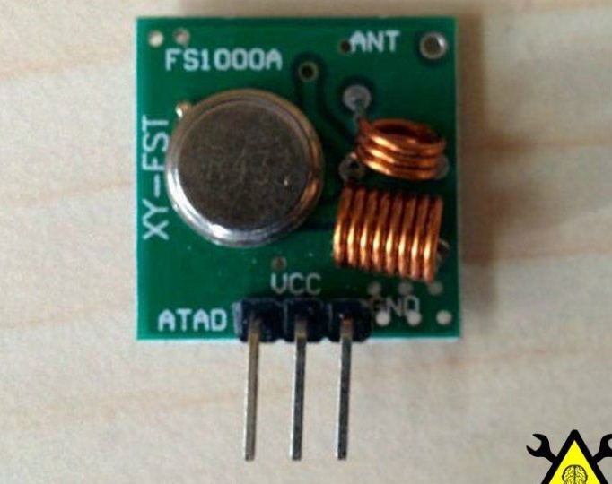
According to the scheme a little lower.
The transmitter has 3 outputs (VCC, GND, and Data), connect them:
- VCC> 5V output on the board;
- GND> GND;
- Data> 12 pin on the board.
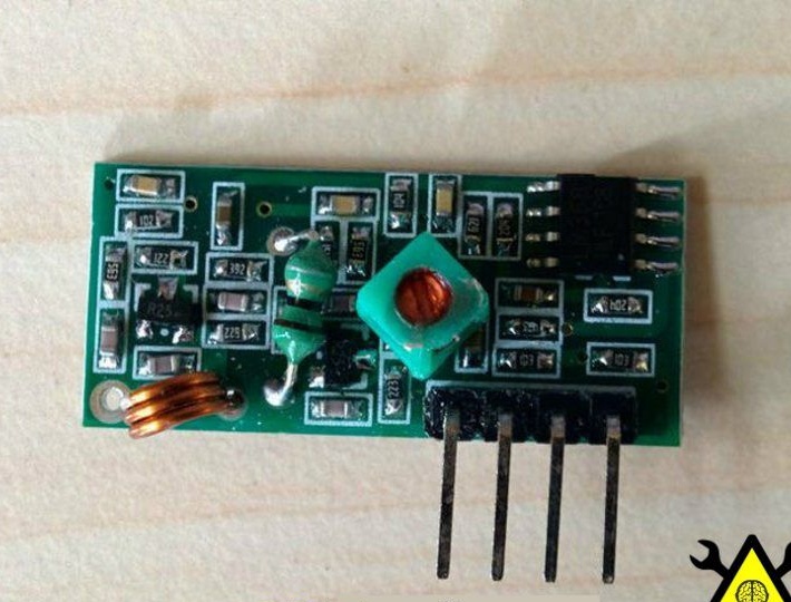
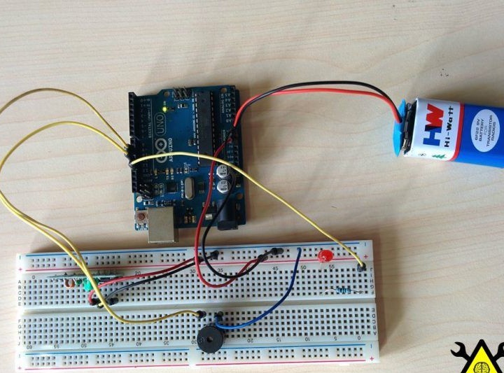
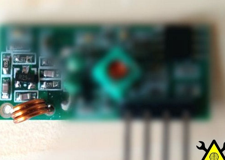
The receiver itself consists of:
- RF receiver module;
- Arduino boards
- Buzzer (speaker).
Receiver Circuit:
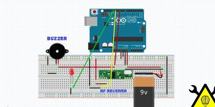
The receiver, like the transmitter, has 3 outputs (VCC, GND, and Data), connect them:
- VCC> 5V output on the board;
- GND> GND;
- Data> 12 pin on the board.
The author chose the file library as the basis of the entire firmware. I downloaded which he and placed it in the folder with the Arduino libraries.

Before downloading the firmware code to the board, the author set the following IDE parameters:
- Board -> Arduino Nano (or the board you use);
- Serial Port -> COM XX (check the com port your board is connected to).

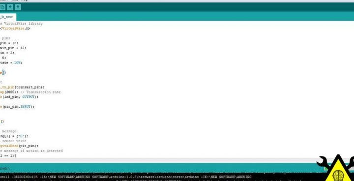
After setting the parameters, the author downloaded the Wireless_tx firmware file and uploaded it to the board:
View online file:
The author repeats the same steps for the host board:
- Board -> Arduino UNO (or the board you are using);
- Serial Port -> COM XX (check the com port your board is connected to).


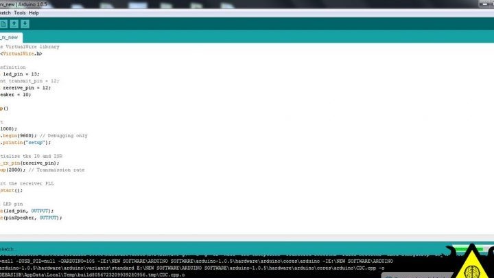
After the author has set the parameters, downloads the wireless_rx file and downloads it to the board:
View online file:
Then, using a program that can be downloaded, the author generated a sound for the buzzer.
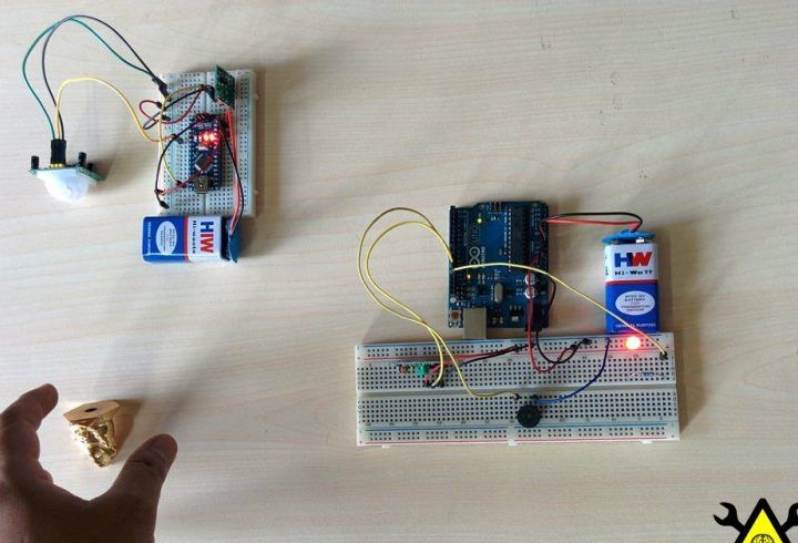
Further, after downloading the software, the author decided to check whether everything is working properly. The author connected the power sources, and ran a hand in front of the sensor, and a buzzer started working for him, which means that everything works as it should.
Transmitter Final Assembly
First, the author cut off the protruding conclusions from the receiver, transmitter, arduino boards, etc.
After that, I connected the arduino board with a motion sensor and an RF transmitter using jumpers.
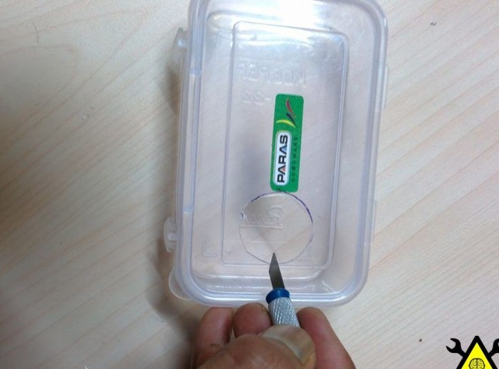
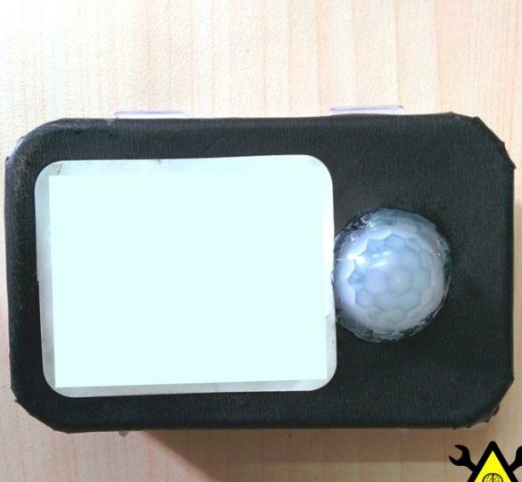
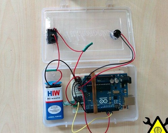
Further, the author began to make a housing for the transmitter.
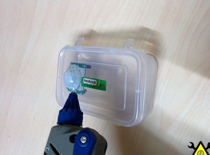
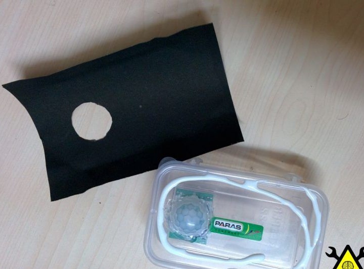
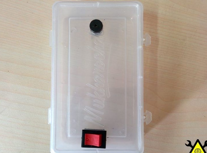
First, he cut out: a hole for the switch, as well as a round hole for the motion sensor, and then glued it to the case.
Then the author folded a sheet of colored paper, and glued it to the front cover of the image in order to hide the internal parts of the homemade product.
After which, the author began to embed electronic stuffing inside the case, using double-sided tape.
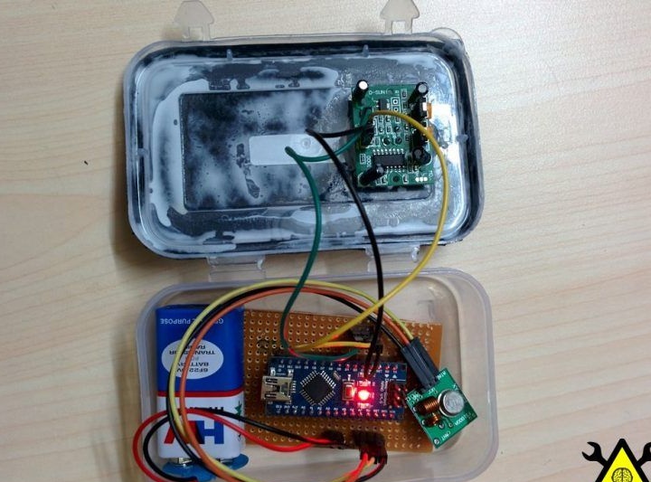
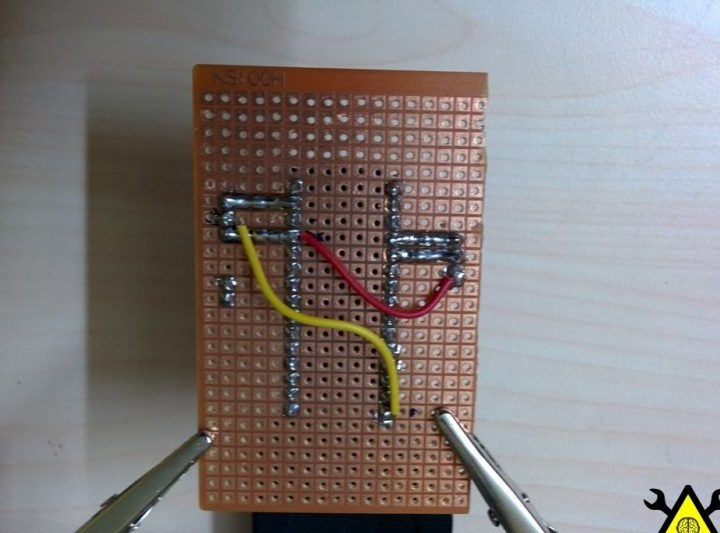
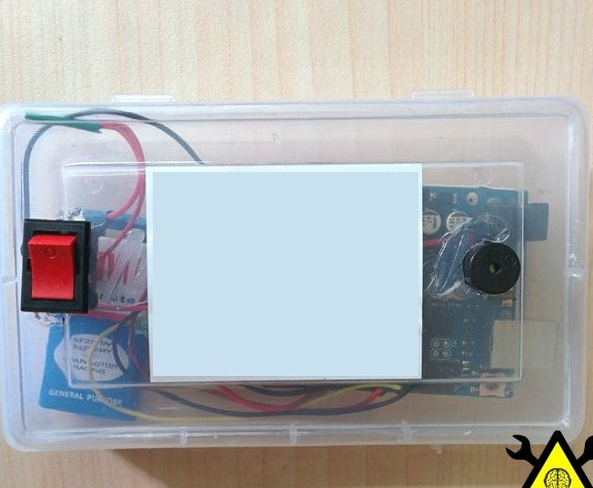
Final assembly of the receiver
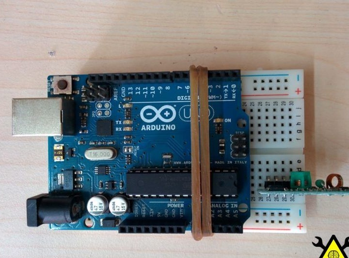
The author decided to connect the Arduino board to the circuit board with a rubber tape, and also install an RF receiver.
Further, the author cuts out two holes on the other case, one for the buzzer and one for the switch.
And sticks.
After which, the author installs jumpers on all the details.
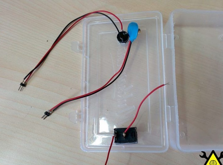
Then the author inserts the finished board into the case, and fixes it with double-sided glue.
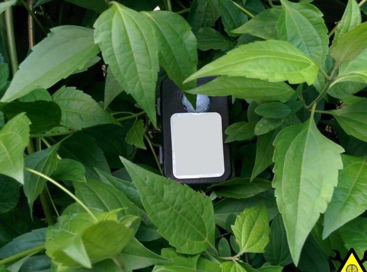
Further, as both modules were placed in the housing, the author placed the transmitter in a place that needs to be protected, and the receiver to his desk.
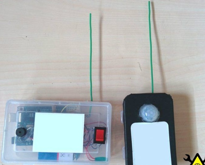
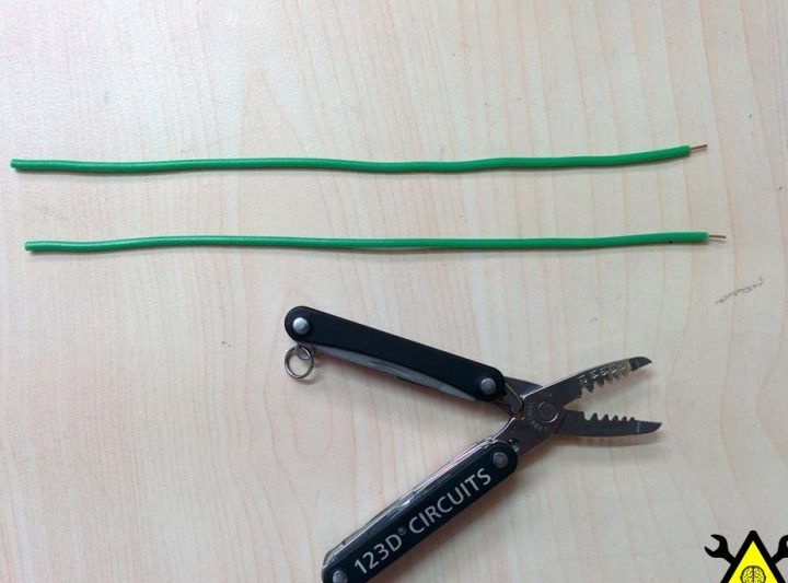
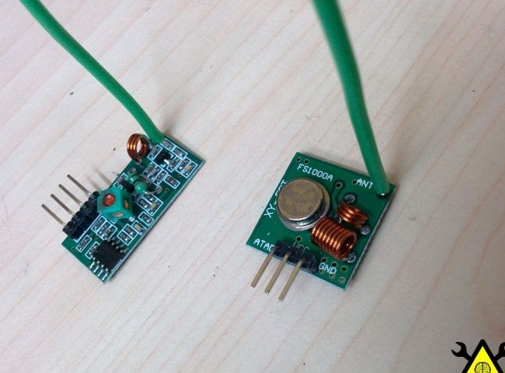
The range of action of the modules is not very large, and therefore, having found a hole marked "ant", the author decided to increase the radius of action by adding antennas to each module.
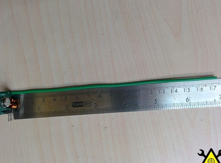
After that, he began to consider how long the antenna he needed.
To calculate the antenna length, you need to determine the wavelength, and for this you need to divide the speed of light by frequency, and then divide the resulting number by 4. The author has a frequency of 433 MHz, and the speed of light 3 * 10 ^ 8 m / s.
Then the wavelength = (3 × 10 ^ 8) / (433 × 10 ^ 6) = 0.69284 m.,
And the antenna length = 0.69284 / 4 = 0.1732 m = 17.32 cm
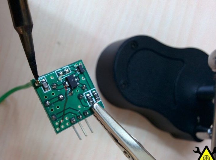
Then the author cut two pieces of the desired length, and soldered them into the holes in each module.
And in the end, he got an arduino-based wireless alarm.