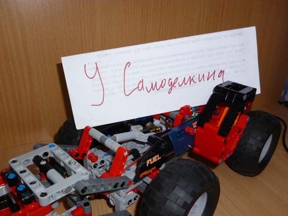
I took part of my design from the Lego Technic 42049 assembly instructions. The rest is my improvisation. For management, I will use a Bluetooth module connected to an android device or computer.
So we need:
- Lego Technic 42029
- Lego Technic 42033
- Arduino Pro Mini 5v AT Mega 328
- 2 L9110S Engine Drivers
- 1 servo drive SG-90
- Bluetooth module HC-05 or equivalent
- USB-UART for arduino firmware
- Mini gear motor 50 rpm
- Mini motor gearbox 100 rpm
- Motor gearbox 6v 150 rpm
- 2 LEDs
- 2 resistors 150 ohms
- Capacitor 10v 1000uF
- 2 single row combs PLS-40
- Inductor 68mkGn
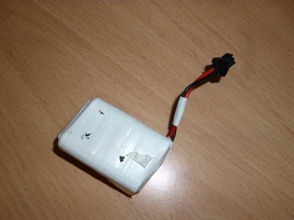
- 6 NI-Mn 1.2v 1000mA batteries
- Connector dad-mom two pin to wire
- Homutik
- Wires of different colors
- solder
- Rosin
- soldering iron
- Bolts 3x20, nuts and washers for them
- Bolts 3x40
- Bolts 3x60
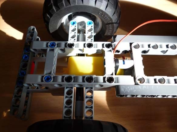
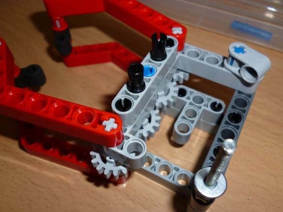
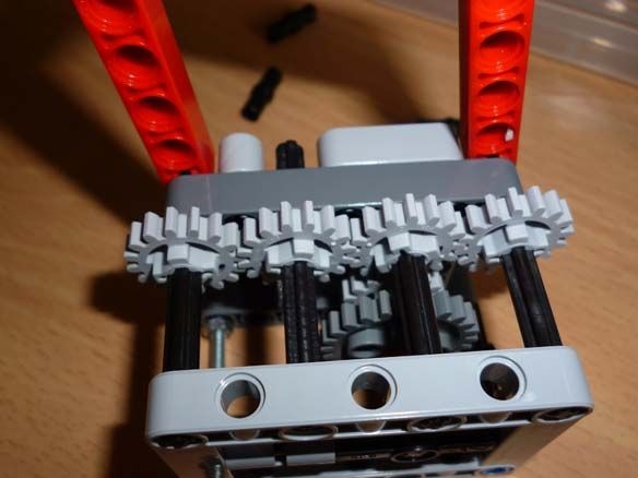
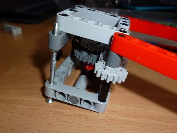
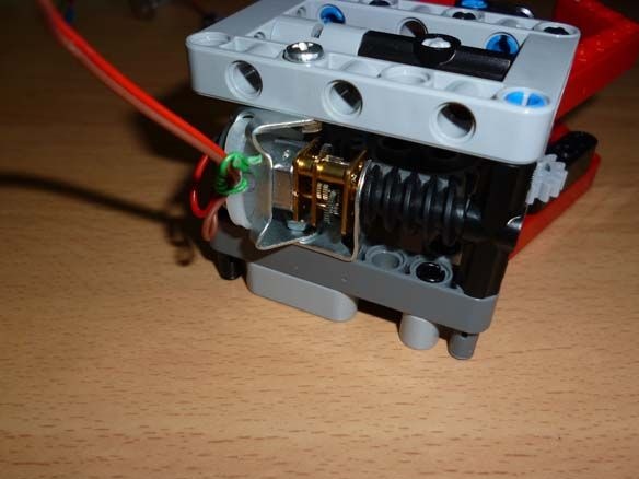
Step 1 Rear Axle Assembly
For movement, we will use a gear motor with a 6 volt motor at a speed of 150 rpm. The gearbox axis must be cut from both sides and put on lego parts. The rear axle is assembled as follows:
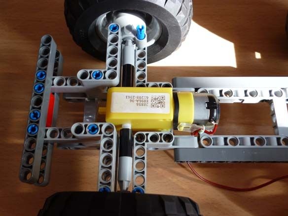
And on the flip side:
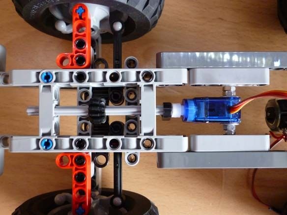
Step 2 Assembling the Front Axle
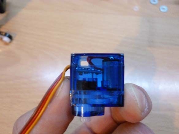
For the rotation of the wheels, the SG-90 servo is well suited. To fix it on our model, it is necessary to carefully drill, so as not to touch the internal parts of the servo, a through hole with a diameter of 3.2 mm or just cut it with a stationery knife. And also cut off the protruding parts (“wings” for fastening). We insert a bolt into the hole made and fix it with nuts. On the servo shaft we put on a lever with a screwed part from lego:
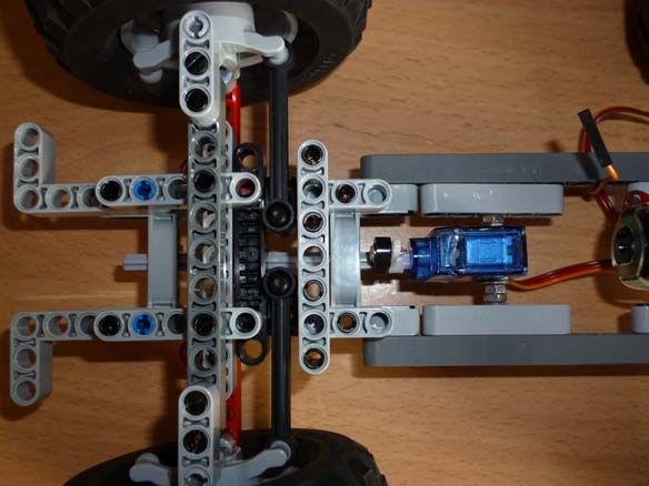
And on the flip side:
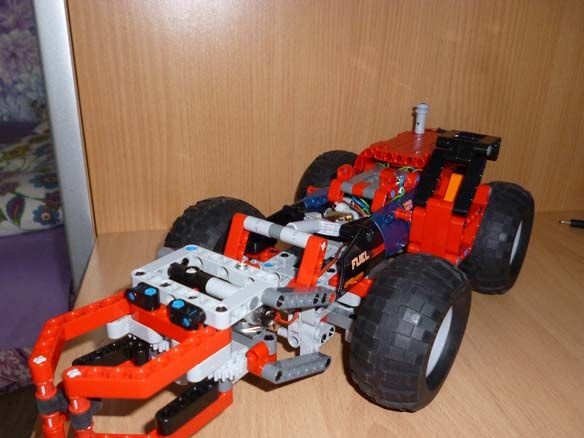
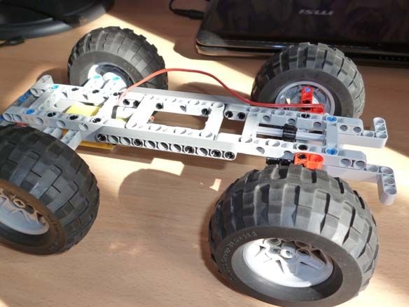
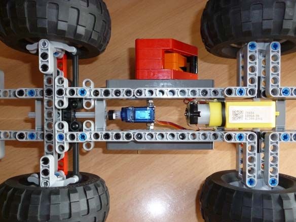
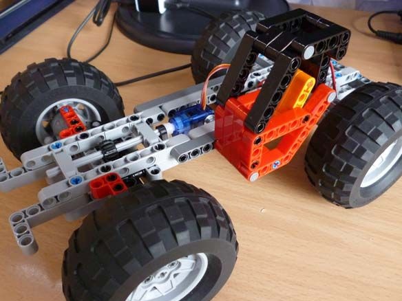
Step 3 Assembling the base and cab
We connect both bridges as shown in the photo:
We assemble the cabin (needed for beauty):
We put the cabin on the basis of:
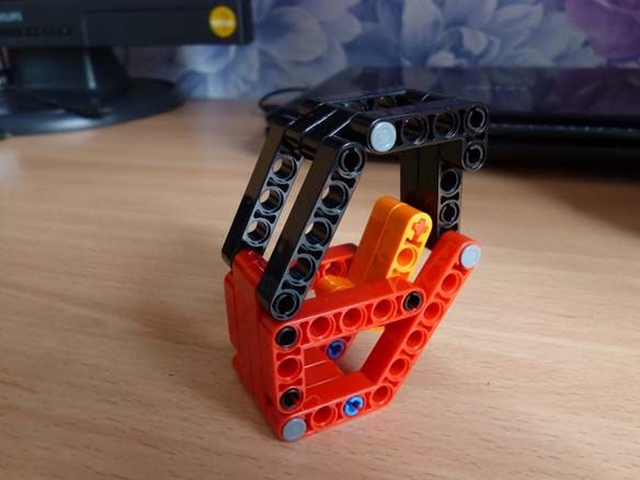
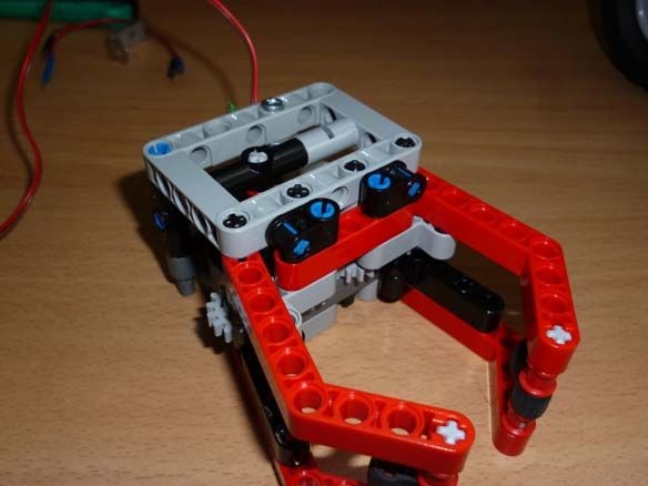
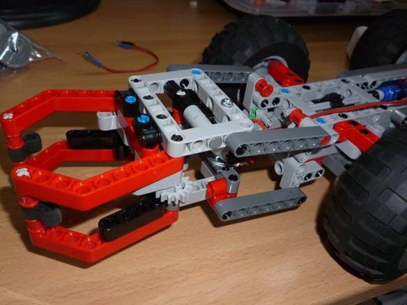
Step 4 Putting a Cap or Claw
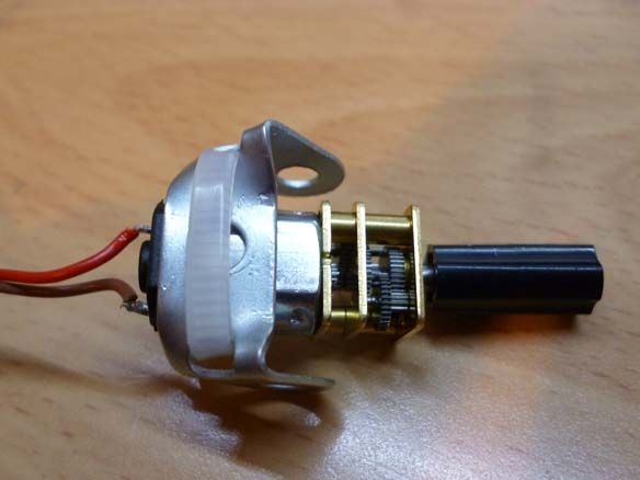
The claw is driven by a mini motor gearbox at a speed of 50 rpm. I solved the problem of connecting the gear motor with the parts of the designer as follows: I put a connecting sleeve on the gear motor axis and inserted a scrap of a match for fixing. For mounting, the gear motor used metal plastic from an iron designer and a clamp. It turned out the following:
Next, we collect the claw itself from the photo:
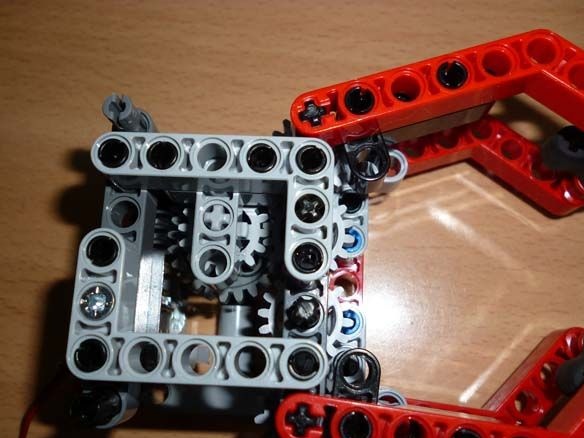
We fix it to the base:
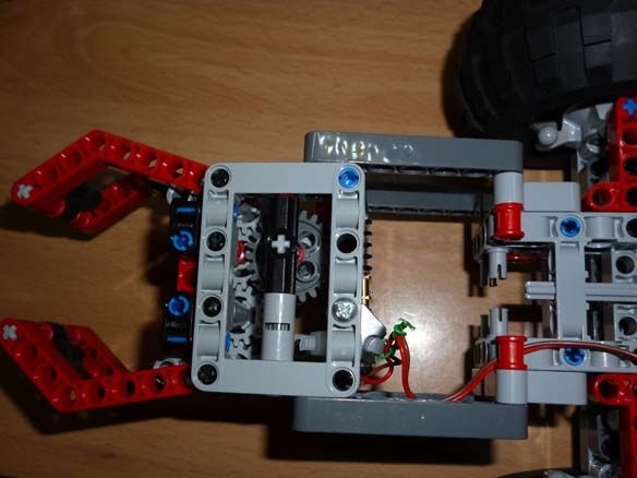
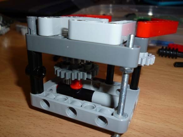
A mini motor gearbox with a speed of 100 rpm is suitable for lifting a claw:
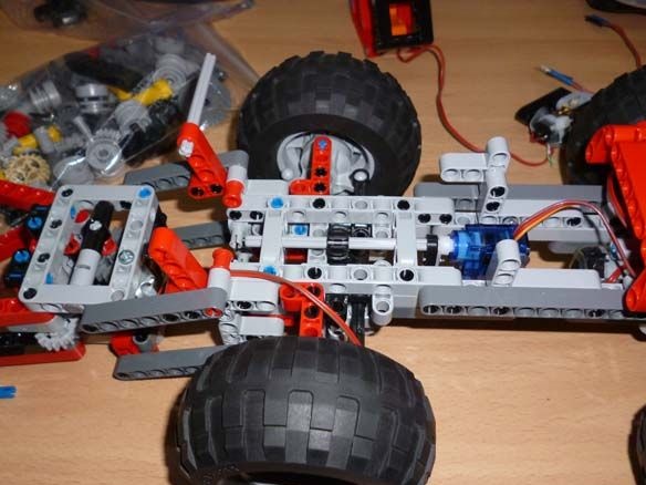
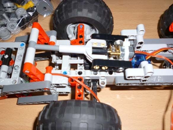
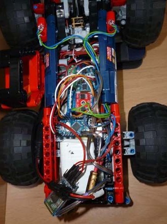
Step 5 Electrician
For control, we will use the Arduino Pro Mini and the Bluetooth module. Motor drivers are needed to connect the motors.
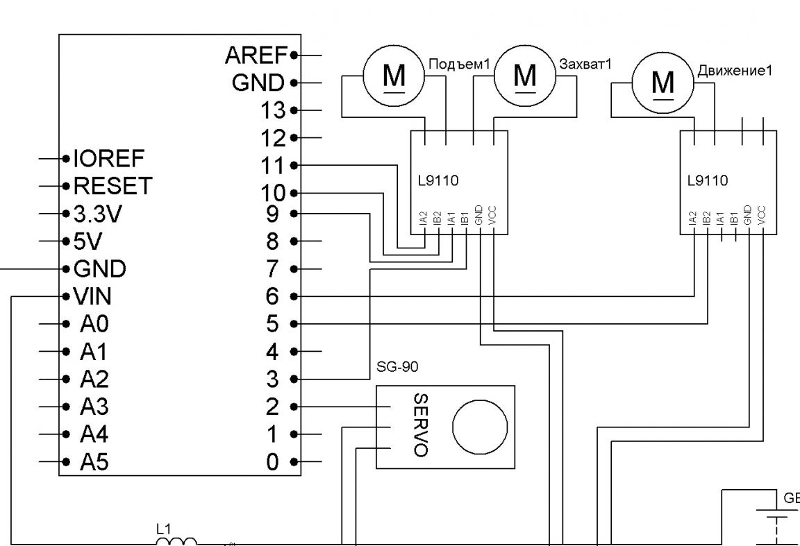
Connection of all components with Dupont mother-to-mother wires.Power - 6 NI-Mn 1.2v 1000mA batteries connected in series. A capacitor of any low power, an inductor also you will find, you need to stabilize the power of the microcontroller. The anodes of the two LEDs are connected to 4 pin arduino, the cathodes to GND. Resistors are selected for the LEDs used. For convenience, reel the batteries with tape.
We glue it all on a double-sided tape on the basis of:
Step 6 Bluetooth Setup
The most affordable Bluetooth modules today are the HC-05 and HC-06. They are abundant in Chinese online stores. The differences between them are that the first can work both in master mode (slave) and in slave mode (master). The second is a purely slave device. In other words, HC-06 cannot detect a paired device and establish a connection with it, it can only obey the master.
Brief characteristics of the modules:
- Bluetooth chip - BC417143 manufactured by
- communication protocol - Bluetooth Specification v2.0 + EDR;
- radius of action - up to 10 meters (power level 2);
- Compatible with all Bluetooth adapters that support SPP;
- The amount of flash-memory (for storing firmware and settings) - 8 Mbit;
- the frequency of the radio signal - 2.40 .. 2.48 GHz;
- host interface - USB 1.1 / 2.0 or UART;
- power consumption - the current during communication is 30-40 mA. The average current value is about 25 mA. After the connection is established, the consumed current is 8 mA. There is no sleep mode.
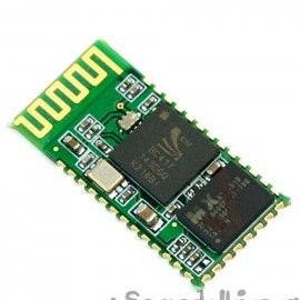
Usually, modules are sold as two boards soldered together. The smaller one is a factory module, widely used in various electronic devices. Large - a special breadboard for DIY. It looks like a smaller board with a BC417 chip:
And so the DIY modules HC-05 and HC-06 themselves:
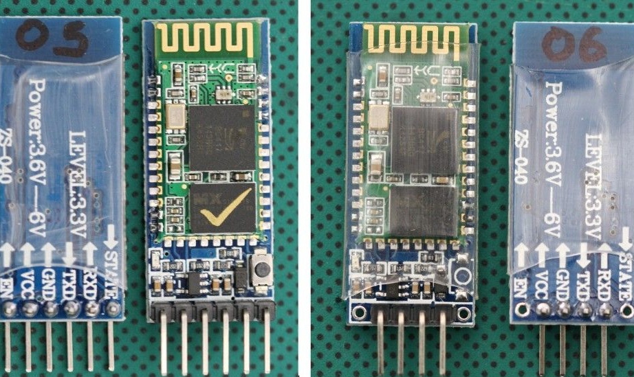
In principle, you can use any module you like. A module without a breadboard costs less, but then you will have to take care of the 3.3 V power supply for the module and torment yourself by soldering wires to the module. I chose the optimal, in my opinion, in the price / functional ratio HC-06.
We connect as follows:
Arduino Pro Mini - Bluetooth
D7 - RX
D8 - TX
5V - VCC
GND –GND
For proper operation, the module must be configured. We will configure AT commands entered into the terminal window. I give an example of setting up the HC-05 module. If you have a different setting may be different. In order for our module to receive commands, first we flash the Arduino with the following firmware:
In this case, Arduino act as a bridge between computers and the module. In the firmware, I use the SoftwareSerial library. At high speeds, it works unstably. If you want high speed, you can connect the module directly to the Arduino RX and TX contacts and rewrite the firmware. But in my case, we will work with the module at a speed of 9600. So after the firmware, open the terminal and enter:
“AT” (without quotes) the answer “OK” should come (it means everything is connected correctly and the module is working)
“AT + BAUD96000” (without the quotes) the answer “OK9600” should come.
If you have the right answer, go to the next step.
Step 7 Firmware
To write the firmware and the firmware itself, I use the Arduino IDE. The current version for today is 1.8. Actually firmware:
Step 8 Set up your phone.
On an Android phone, you need to install a program to control the robot via Bluetooth. There are a lot of them. You can enter “Bluetooth Arduino” in Google play and choose to your taste. I liked the BT Controller. Download and install on your Android phone or tablet. Next, through the Android settings, you need to establish a connection with our module. The password for the connection is “1234” or “0000”. Next, configure the program for the appropriate commands. The list is below.
Step 9 Computer Setup (if necessary)
If necessary, or just convenience for control, you can use a computer or laptop. To do this, the computer must have Bluetooth. We establish communication with our module through the controls on the computer. Next, we need a terminal to send commands. Any convenient for you. Having recorded the firmware, control is performed by the following buttons (commands):
W - forward
S - back
A - left
D - right
F - stop
G - steering wheel
K - headlights
L - headlight off
R - lift up
E - downhill
Q - stop lift
T - capture
Y - Release
H - Stop Claw
Constantly entering commands is inconvenient, so I recommend using the program to send commands. I am using Z-Controller.In the program, select the port (com port through which the connection is made) and configure the keys for the commands. Set up idle and intuitive.