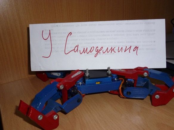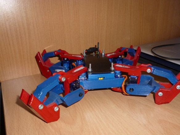
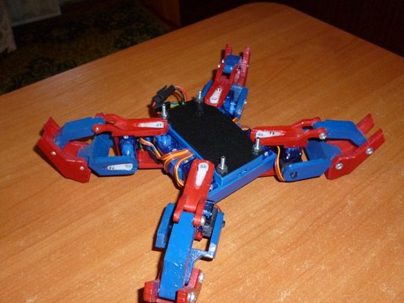
Good afternoon, today I will publish the instructions for manufacturing a quadropod - a four-legged robot. The robot parts are printed on a 3D printer as a controller - ESP8266, but you can use Arduino, Nano or Mini for example. Management via web - interface. Wi-Fi connection.
As I said earlier - the details are printed on a 3D printer. If you have any problems, if not, you will need to find someone to print or order a print.
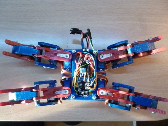
Four-legged robot video:
So we need:
- ESP 8266 - 12E
- voltage regulator 3.3v
- Batteries Li-ion 18650 2 pcs.
- Servo SG-90 8 pcs.
- switch
- button
- wires
- PLS connector
- USB-TTL
- 3x20 bolts
- nuts and washers 3mm
- drill 3.2
- drill or screwdriver
Step 1 Case.
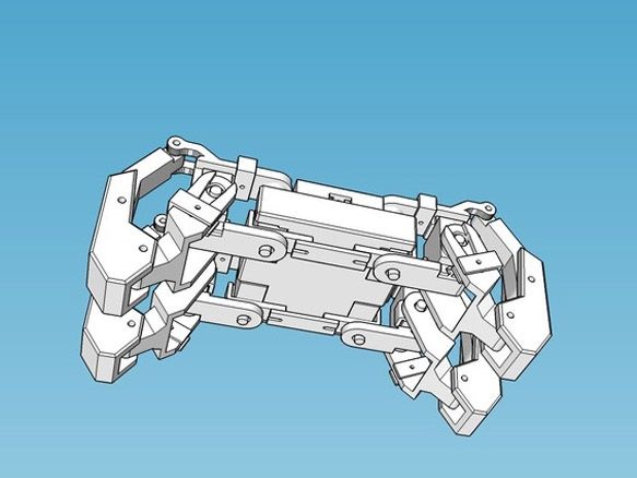
To make the body and legs, you need to print the following parts on a 3D printer:
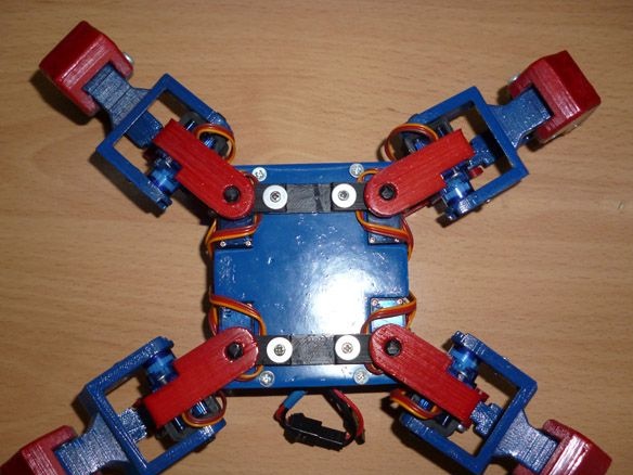
I draw your attention to the fact that the files k_body and k_others need to be printed once, and the file k_legs two! You can print in any color. We carry out the assembly according to the scheme:
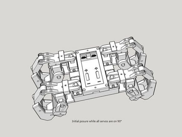
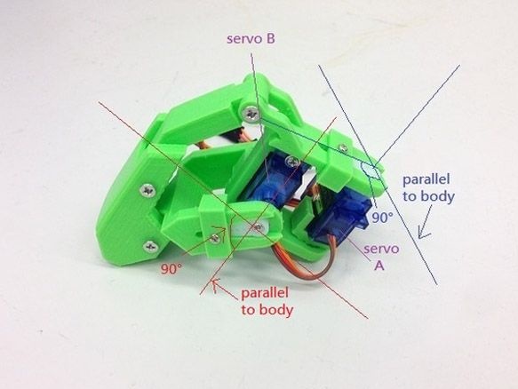
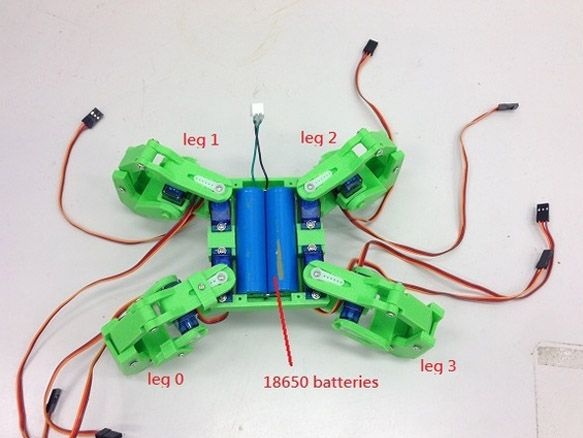
At the joints on the legs we use 3x20 bolts, insert the batteries inside the case and remove the wires, connect them in parallel. Do not forget to remove an additional pair of wires for charging, it will be very inconvenient to then remove the batteries for charging, it is much easier to immediately remove a pair of wires with a connector. When assembling, make sure that all servos are in the 90-degree position. To set the servo to 90 degrees, you need to connect it to the controller (Arduino for example) and use a simple code to rotate the servo. You can do this manually. To do this, put the lever on the servo shaft and turn it until the stoppers on the gear are in the middle. This must be done very carefully, since the gears are plastic and there is a high probability of breaking off the teeth. I recommend using the first option, it is certainly longer, but the servo will definitely remain intact.
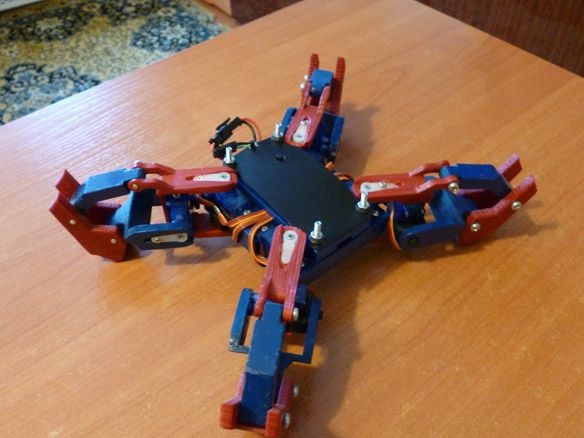
At the last moment I decided to paint my model in blue-red color.
Step 2 Electrician.
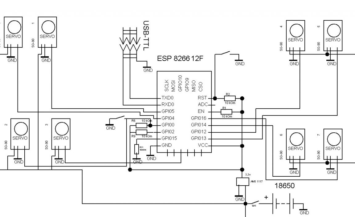
And here several options are possible. In my opinion, the most optimal is to use the ESP 8266 - 12E as a controller. Firstly, it has the required number of pins to connect all the servos.Secondly, the built-in Wi-Fi module, which greatly facilitates the management and connection process. Third, you can easily program in the Arduino IDE. It is best to choose a module with 4 Mb of memory. So, to run and flash the ESP-8266, you need to do a minimum binding. Only the VCC pin is directly connected to the power supply, the remaining pins: CH_PD, RESET, GPIO0, GPIO2, must be pulled to the power supply (VCC) through the resistor. 10kOm resistors can be replaced with others, from 4.7kOm to 50kOm, except for GPIO15 - its value must be up to 10k. Directly, to the minus (GND) of the power supply, we connect only GND, and we also pull GPIO0 through the resistor to 10kOm, to put the module into the firmware download mode, to GND. Do not forget to add a button to reboot and bring out the USB-TTL connector for firmware. For all servos, we cut the wires so that they do not interfere and do not hang out, but at the same time it is free enough so that the legs can move quietly. We connect all the red wires from the servos directly to the plus of the batteries, and the brown wires to the minus. Solder the orange wires to the ESP according to the scheme:
The servos are numbered as follows:
Servo 0 - GPIO4 (when viewed from above the lower left leg, the drive on the case)
Servo 1 - GPIO5 (lower left leg, foot drive)
Servo 2 - GPIO0 (upper left leg, drive on the chassis)
Servo 3 - GPIO10 (upper left leg, foot drive)
Servo 4 - GPIO12 (upper right leg, drive on chassis)
Servo 5 - GPIO13 (upper right leg, foot drive)
Servo 6 - GPIO14 (lower right leg, drive on chassis)
Servo 7 - GPIO16 (lower right leg, foot drive)
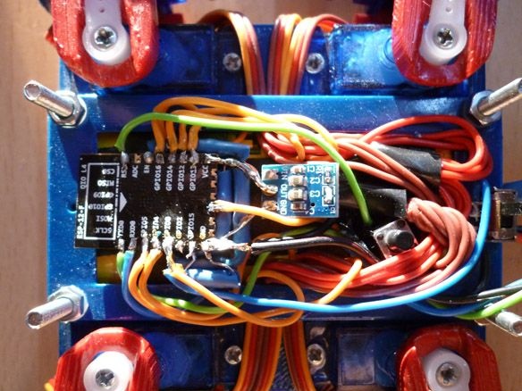
It is most convenient to solder the minimum strapping of resistors first. Then we glue the ESP itself on a double-sided tape, and after that we solder all the wires from the servos, we forget about the voltage stabilizer for ESP. The ESP is powered through a 3.3 volt stabilizer, and the servos drive directly to the batteries.
I'll tell you a little about other options. You can use Arduino Mini or Nano as a controller. Then we connect all servos to Arduino, and to carry out communication through ESP 8266-01. In ESP, it will be necessary to fill in the firmware for transmitting Arduino commands and connect it to the Arduino RX TX pins. In this case, both the circuit and the firmware are different. Next time I will write instructions for this option, but for now, let's return to our ESP 8266-12E.
Step 3 Preparing the programming environment.
To write and edit firmware for ESP, you must install the add-on for ESP under Arduino IDE via Boards Manager:
1. Install the Arduino IDE from the official Arduino.cc website
2. Launch the Arduino IDE, then File - Settings - in the Additional Boards Manager URLs field, insert a link to the stable version http://arduino.esp8266.com/package_esp8266com_index.json
or for nightly build http://arduino.esp8266.com/staging/package_esp8266com_index.json click OK (in this field you can enter several links separated by comma)
3. Tools - Board - Boards Manager
4. In the Boards Manager, enter esp8266 in the filter field or manually scroll through the list and click on the ESP8266 by ESP8266 Community Forum
5. Click Install and wait for the download to finish (about 130 megabytes). If the download is too fast, it is possible that you have already installed the Arduino IDE for ESP8266 and you need to clear the Boards Manager cache, otherwise you will still have the old version installed. You must first uninstall the old version, and then you need to delete the cache files. For Win7 x64, delete the files from the folder C: \ Users \ User \ AppData \ Roaming \ Arduino15 and repeat everything from step 2
6. Close Boards Manager and on the Tools menu, select Board - Generic ESP8266
7. Set the frequency of your module to 80 or 160Mhz, size of flash memory and select the serial port to which your USB-TTL adapter is connected
8. You also need to add files from the archive to the tools folder (located at the Arduino IDE installation location) to access the ESP file system.
Step 4 Firmware.
It remains to edit the sketch and fill it with ESP.
In the field "String _ssid =" ";" between quotes indicate which access point you want to connect to.
"String _password =" ";" is the password for this network.
"String _ssidAP =" Quadrapinky ";" the name of the network that the ESP will raise if it does not connect to the existing one.
"String _passwordAP =" 12051005 ";" - the password of the network that the ESP will raise if it does not connect to the existing one.
"String SSDP_Name =" Quadrapinky ";" SSDP name
Remember to upload additional files to ESP. This is done through the Tools tab - ESP8266 Sketch Data Upload
After starting, ESP tries to connect to the access point specified in the sketch, if successful, you need to determine the IP address of our robot and connect to this address through a browser. You can also go through a computer to the network infrastructure, find our robot there and double-click to connect to it. If the connection fails, the ESP becomes the access point. Then access can be obtained by connecting to a new access point and entering 192.168.1.1 in the browser.
The web interface consists of two pages. The first to control. The second is for customization. On the second page, you can specify the access point to which you want to connect, as well as the name of the robot and the name and password of the access point that the ESP lifts. All changes take effect after a reboot. You can also restart the module via the web interface.