

Recently I was approached with a complaint about extremely inaccurate work. electronic hours. For a week they ran ahead for several minutes. The watch was made and purchased more than 10 years ago, but for the reason given it was not used. The reason to return to them again was the burnout of the indicator segments on other working hours.
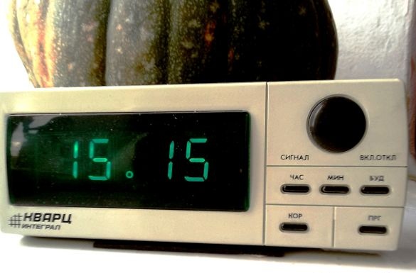
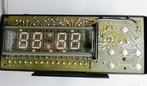
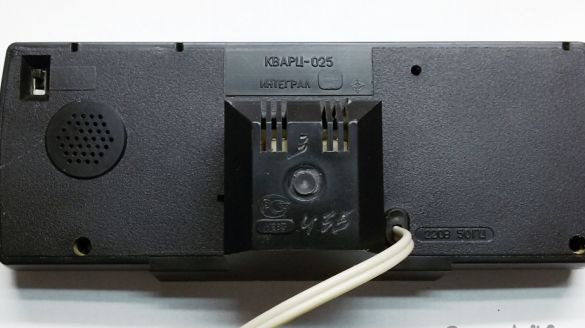
An electronic desktop clock with a signaling device “Quartz-025 Integral” was manufactured by OJSC “Electronics” in the Karachay-Cherkess Republic.
The alarm clock is designed to display the current time in hours and minutes on the LED indicator, with the ability to manually set the current time and time of the alarm, to issue a musical sound signal in the alarm mode. The clock is powered by 220 V.
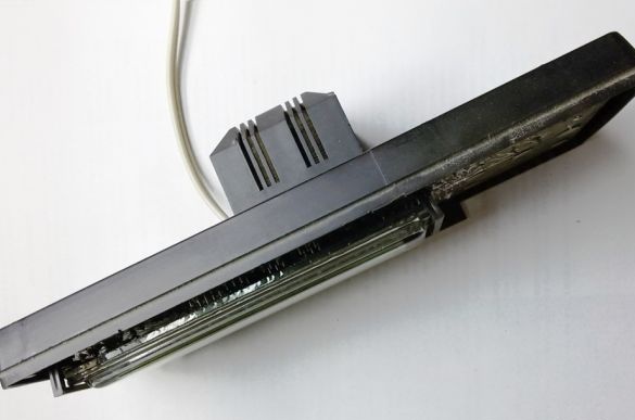
Advantages of the watch: Bright large numbers, perfectly visible from afar, can actually play the role of a night lamp. The watch has simple settings, takes up little space and works from the network. The power supply transformer of the clock is successfully placed outside the board. It cools well and serves as a stable support for table clocks.
Disadvantages: Low accuracy of the watch and the lack of customization. The lack of brightness adjustment indicator. Low volume alarm. The alarm ringtone selection button does not work.
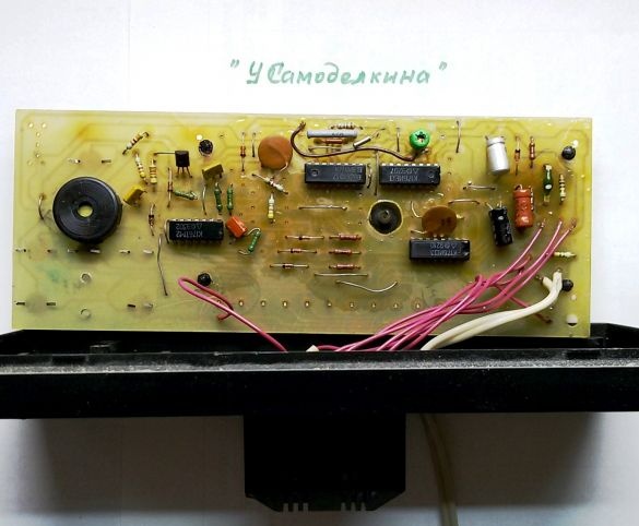
After opening the watch case, it turned out:
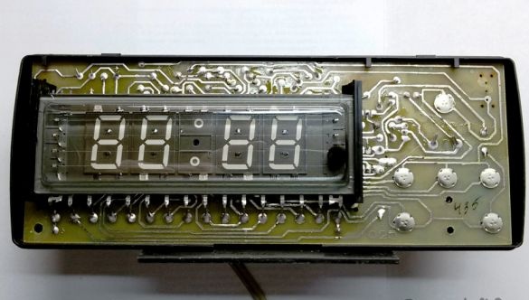
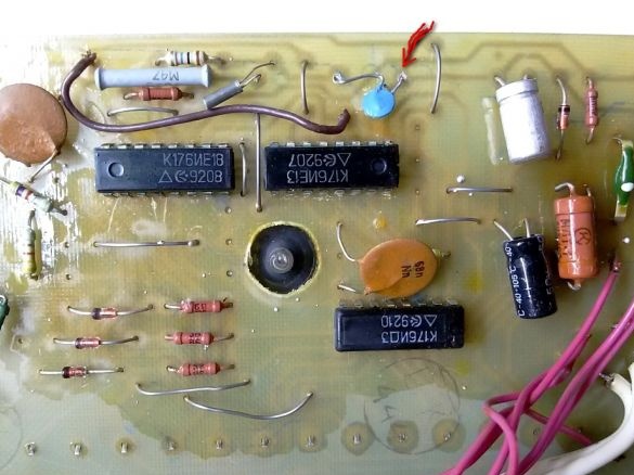
- The watches are assembled on the basis of a typical circuit on widespread “clock” microcircuits of the K176 series - K176IE18, K176IE13, K176ID3 and the vacuum-luminescent indicator IVL-7/5.
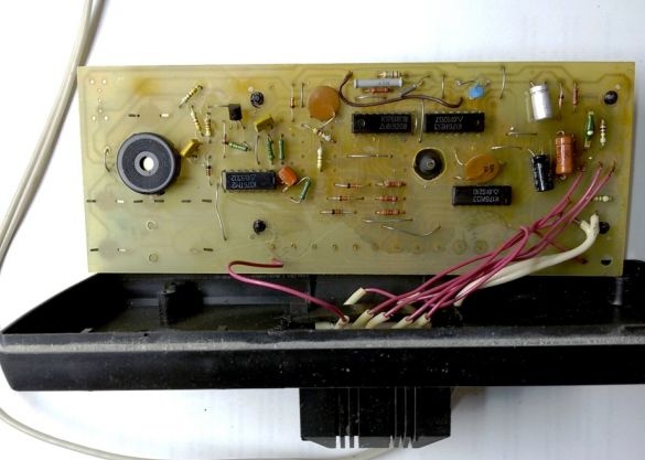
- The wiring diagram is greatly simplified, which reduces operational characteristics, but the watch board partially provides for the possibility of its development.
- Instead of a “musical” UMS7-04 chip with a set of melodies, a transistor unit with one simple melody and an output to a piezoceramic emitter is installed. Therefore, the melody selection button is decorative.
Let’s go over the revision of the scheme.
Consider a typical circuit for switching on the K176IE18 chip:
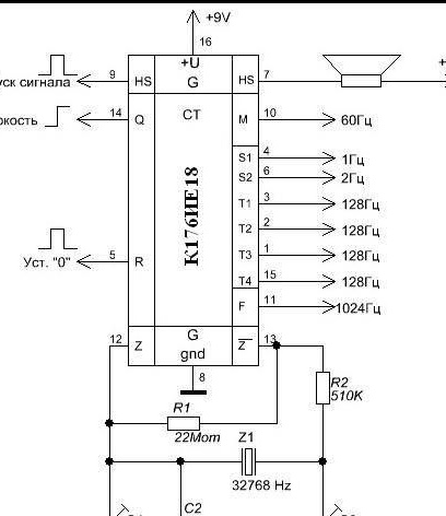
The leading microcircuit K176IE18 was developed specifically for working in electronic clock circuits. The K176IE18 chip includes a generator (pins 12 and 13), designed to work with an external quartz resonator (Z1) with a frequency of 32,768 Hz. An external capacitor C3 serves to fine-tune the frequency.
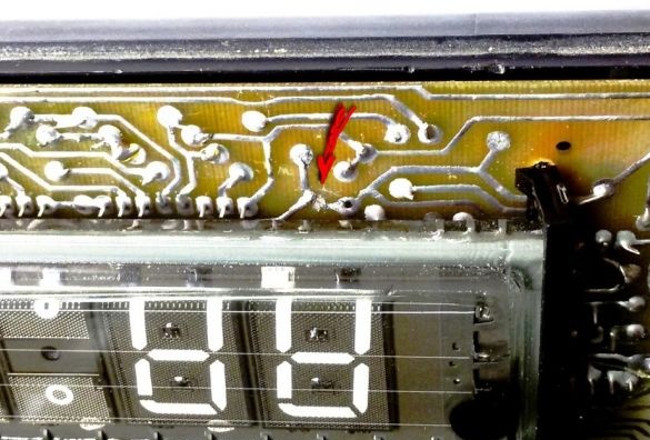
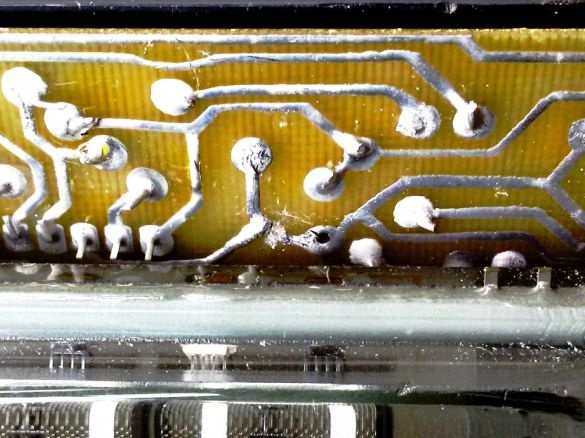
In a real wiring diagram, this element could not be found. Instead, a permanent capacitor was installed (in the photo below - a blue capacitor, indicated by an arrow). But its capacity does not correspond to the required frequency of the generator, which led to inaccurate hours.
Solder the capacitor and measure its capacitance (10 pF).
The recommended capacitance of the tuning capacitor, according to the typical scheme for switching on the K176IE18 microcircuit, is 4 ... 20 pF. We select a tuning capacitor close in value. We find with a capacity of 5 ... 35 pF.
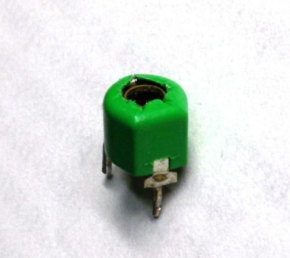
We expose on the device, preliminary, a slightly overestimated capacity and install the capacitor in its place in the board.
We turn on and check the operation of the watch. If necessary, we adjust the generator frequency by changing the capacitance of the installed variable capacitor, accelerating or slowing down the clock.
Large bright green numbers, if necessary, can play the role of a night lamp, but sometimes the bright lights in the night room make it difficult to sleep. It should also be remembered that the vacuum fluorescent indicators of green glow in the dark seem much brighter than in light, so it is advisable to provide for a change in the brightness of their glow.
For this purpose, the input Q is provided in the K176IE18 chip (pin 14 - see the typical circuit for switching on the chip). By applying level 1 (+9 volts) to this input, it is possible to reduce the brightness of the indicator by 3.5 times by increasing the duty cycle of the pulses at the outputs of the microcircuit. Thus, it is possible to stepwise adjust the brightness of the indicator.
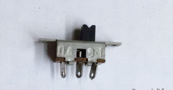
Two-level duty cycle adjustment is carried out by supplying one of two voltages 0 or +9 volts to the input Q. This function can be performed by introducing a two-position switch into the watch design.
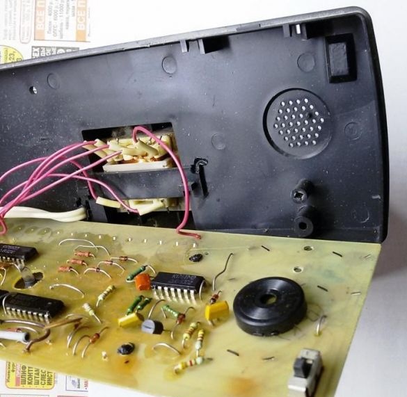
By the way, in the full version of the clock scheme this function was provided, because The board has unused mounting holes, and there is a corresponding relief on the back wall of the watch case.
We drill in the board the necessary additional holes for the switch and install it on the board.
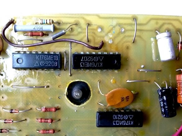
We find on the printed circuit board a path going to the input Q (pin 14) of the K176IE18 chip. In fact, it is soldered to a common wire (0 volts). We cut it with a sharp knife. This place in the photo below is indicated by the arrow (in this version of the watch modification). In other models of watches, PCB options are possible, but there is one goal - to cut off the connection of the leg 14 of the microcircuit with a common wire.
We connect the on-off switch to the circuit.
The average common contact of the switch is soldered to the disconnected leg 14 of the microcircuit. The second contact (one of the extreme - at the discretion) is connected to the common wire. The third remaining contact is connected to the leg 16 of this chip. It is powered +9 volts.
In the back wall of the watch case, in the bottom of the pocket, opposite the installed switch, we drill and cut a rectangular window with a file for the switch engine. We assemble the board and watch case. The switch slider should not touch the watch case. Any defects of the switch (wear, backlash, pitching of contacts, weak spring) will immediately affect the operation of the watch. Stable indexing and clock adjustment will not be possible.
Thus, the installed switch allows you to reduce the brightness of the indicator when the engine is switched to the "9V" position. It should be noted that in this position of the switch, the timing and signaling circuits are blocked. In other words, setting the current time and the alarm is performed only in the “0V” position of high brightness.
The alarm signal, in the circuit, is fed to a piezoceramic emitter. To increase the volume of the emitter, it is possible to use several options. This is an adjustment of the frequency of the generator, to match it with its own sound resonant frequency of the emitter, the introduction of additional amplifiers or controlled oscillators into the circuit, the selection of additional capacitors and inductors to ensure mechanical and electrical resonance. These methods are described in detail on the Internet.
For a slight increase in the volume of the alarm, a simpler way is possible - the selection of another sound emitter (electromagnetic, electrodynamic). For example, the use of a TON-2 earphone with a resistance of 1600 ohms, instead of a piezoceramic emitter, allows you to increase the volume of the signal, to get a pleasant sound tone. There are many options for choosing a sound emitter and it all depends on your capabilities. The selection of another sound emitter was made, but the owner of the watch refused this offer.
Similar changes, to improve performance, are possible on other models of low-cost electronic watches built on the basis of a typical circuit on a series of chips K176, K561.