

You can use this circuit for turn signals on a motorcycle or bicycle.
Let's get started!
To solder this circuit, we need:
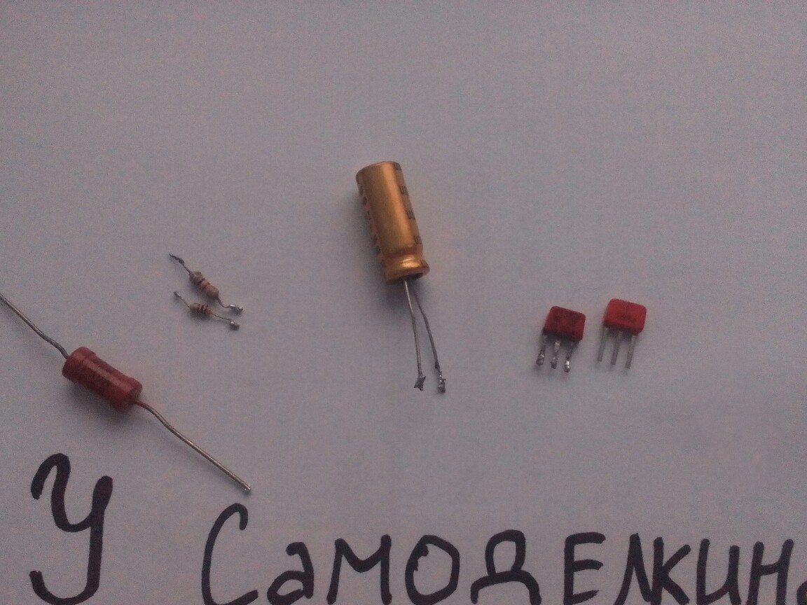
Transistor (n-p-n): KT315
Transistor (p-n-p): CT361
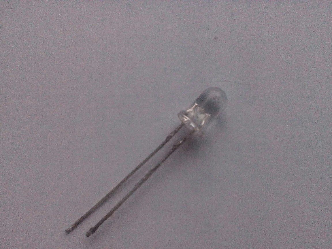
LED 4-5 Volts (it all depends on the voltage that we will feed the circuit)
Resistors:
1.1kOhm
2.100 ohms
3.270-470 kOhm
Capacitor from 100 Mkf (The frequency of LED flicker depends on the capacitance of the capacitor)
And 1 wire
We will solder the canopy (without the breadboard)
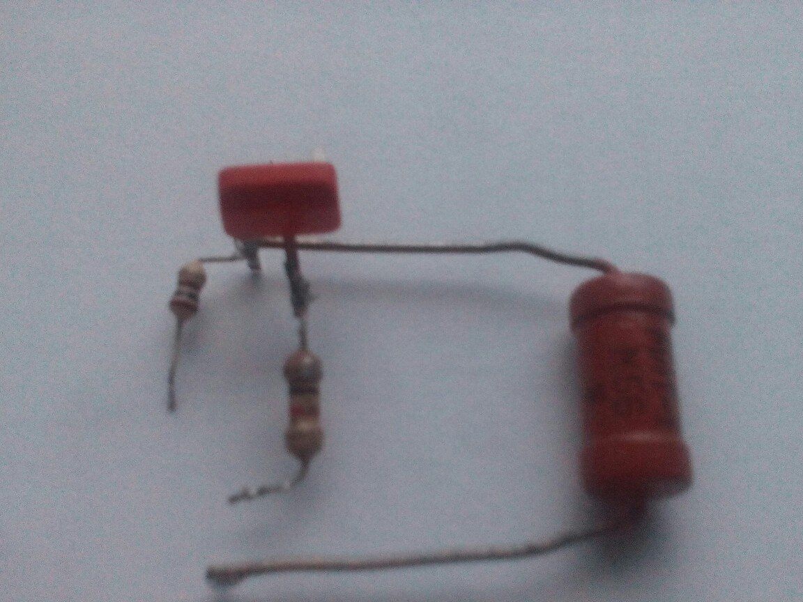
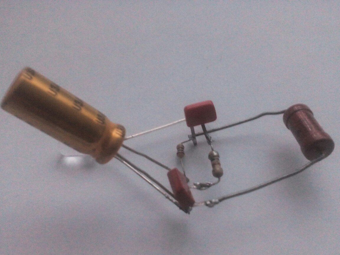
Photos of all components:

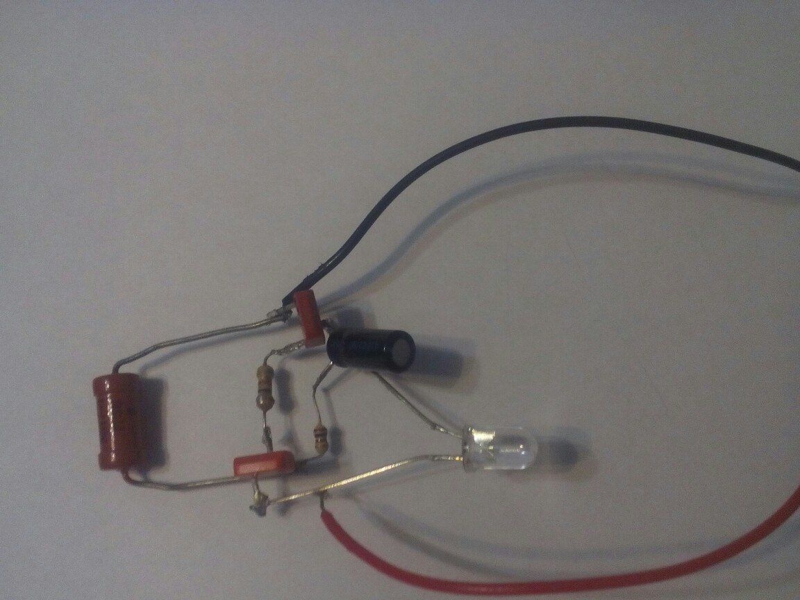
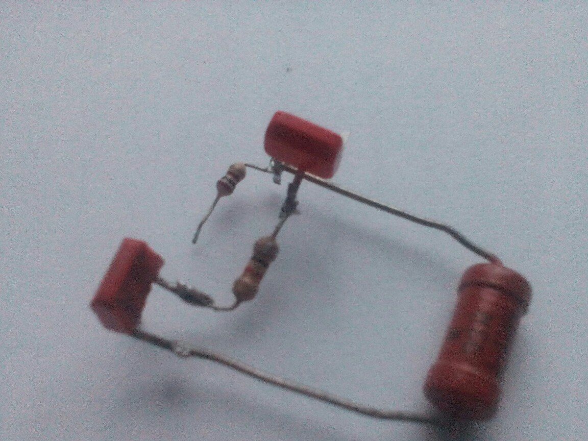
This is how the circuit looks:
VT1- KT361
VT2- KT315
Let's start the soldering!
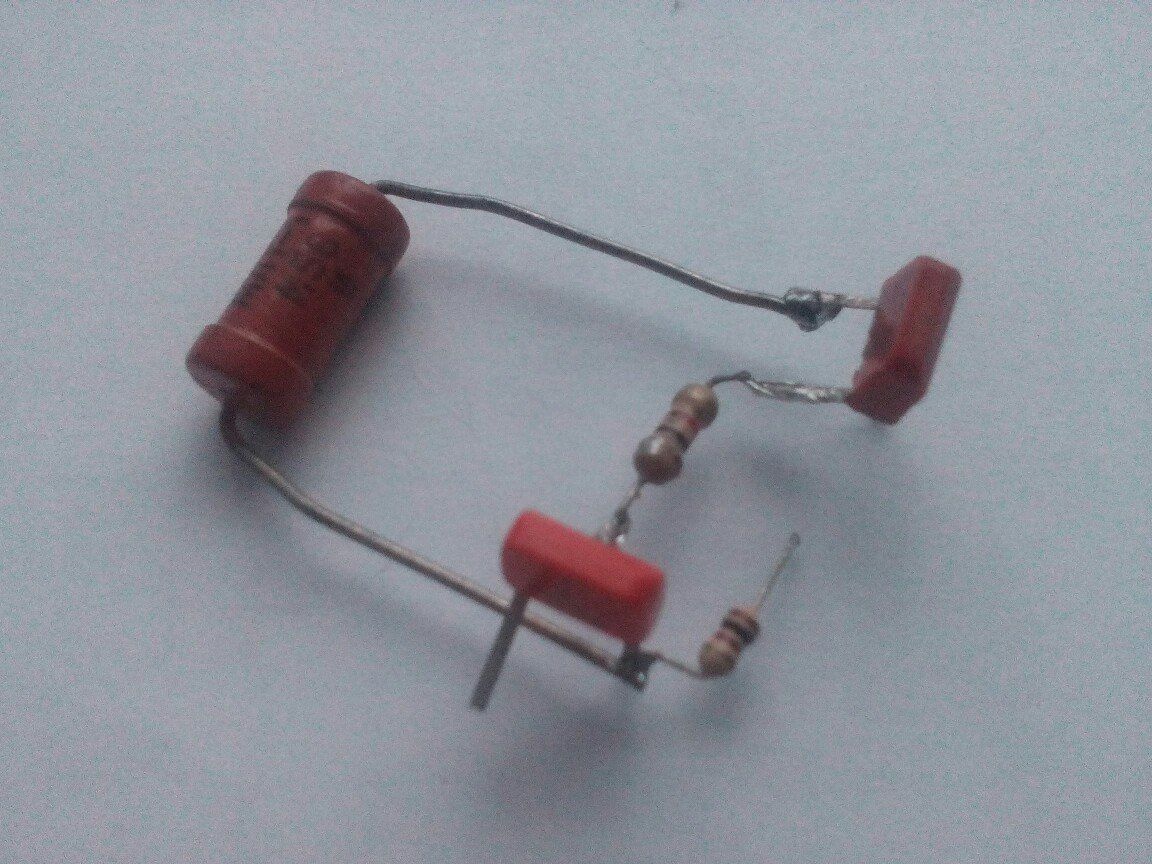
1. We solder the transistor KT361 and 3 resistors.
To the right conclusion, to the base we solder R3 (270-470 kOhm)
Solder the medium to the collector R2 (100 Ohms)
Solder R1 (1 kOhm) to the left emitter
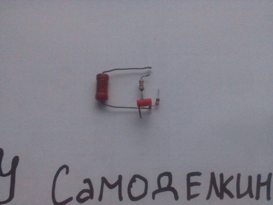
Here's what you should get:
2. To the fact that we managed to solder the second transistor - KT315
3. Solder the capacitor and LED.
The negative output of the capacitor to the negative output of the LED!
4. Connect the power and test the circuit.
I changed the capacitor to increase the frequency of flicker. You can change nothing and leave as well.
5 Volt Power
Video circuit work: