

Waking up at night or early in the morning, you usually want to find out the current time in order to estimate the remaining time before the rise. The room is dark and you do not want to get up to turn on the light. To facilitate this task, the proposed device is intended. It is a night lamp with autonomous power (battery or battery) and LEDs as a light source.
The night light is turned on by some acoustic signal (noise, knock, click, word, clap in the palm of your hand) and turns off after 8 ... 10 seconds. When the signal repeats, the cycle repeats.
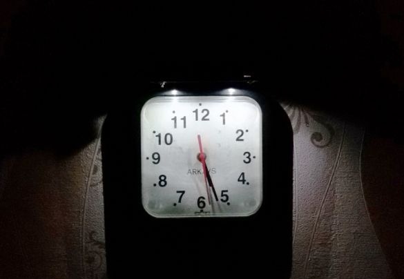
The device is located in a small case, which is installed above the wall clock. When turned on by an acoustic signal, the LEDs illuminate the watch dial and the room in night mode. Due to the fact that the device is autonomous, it can be placed in any convenient place, which expands the possibilities of application.
A feature of this device is that in addition to the acoustic relay, it also uses a photo relay to control the lighting LEDs. Under normal lighting of the room with natural or artificial light, the photo relay does not allow the useless LEDs to turn on, which significantly saves the power consumption of the battery. Moreover, the current consumption of the device does not exceed 1.0 ... 1.3 mA.
The nightlight turns on automatically at nightfall when the resistance of the photoresistor increases. Then, with insufficient lighting in the room, the photo relay activates an acoustic relay, which turns on the backlight for about 10 seconds with any sound exceeding the set level. The dial and clock hands illuminate two LEDs, which have a very high brightness at a consumption current of about 15 mA. The current consumption of the device, in the lighting mode, does not exceed 30 mA.
The night lamp circuit provides for the possibility of regulation over a wide range of sensitivity of the photo relay (R2) and acoustic relay (R9). To disable the photo relay, if necessary, the resistor R2 must be set to the minimum position.
In this circuit, the FSD-1 photoresistor is used as the R1 photosensor. In the role of such a sensor, another photoresistor of domestic or foreign production can be used. The exact value of the resistance of the photoresistor is not so important, since resistor R2 provides for the adjustment of its sensitivity.
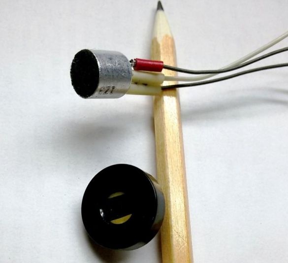
The sensor of the acoustic relay is an electret microphone with a built-in amplifier.
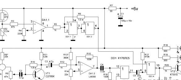
The nightlight circuit is made on two common cost-effective microcircuits - the LM358 two-channel operational amplifier and the K176LE5 logic chip with 4 2OR-NOT elements.
The upper part of the presented circuit performs the function of a photo relay.
The photoresistor together with the resistor R2 forms a voltage divider. When the illumination changes, the resistance of the photoresistor changes and the voltage at input 3 of DA1.1 OA LM358 changes. The difference in the signals at the inputs of the op-amp is amplified and fed to the DD1 chip.
Elements DD1.1 and DD1.2 form a Schmidt trigger, which provides a clear switching of the state and prevents the light circuit from cycling in natural light close to the threshold. As a result, a control signal appears at the output of the photo relay. When lighting the photo-resistance R1, the output 4 of DD1.2 will be log.1, and with insufficient lighting a log. 0.
The lower part of the circuit acts as an acoustic relay.
The sound signal is perceived by the microphone MK. To increase the sensitivity, the microphone is connected to the pre-amplifier on the transistor VT1 and further, to the microphone amplifier on the operational amplifier LM358. The amplified short-term sound signal from the op-amp is fed to a single-shot, assembled on logic elements DD1.3 and DD1.4, which generates a single pulse lasting about 10 seconds. The pulse duration can be changed by selecting the appropriate values of resistor R17 and capacitor C5.
The start and stop of the single-shot operation is carried out by the control signal from the output 4 of the DD1.2 photorelay.
The resulting signal from the output 10 of DD1.4 single-vibrator, is fed to the transistor VT2, which ensures the inclusion of LEDs.
1. We select from the available or purchase accessories.
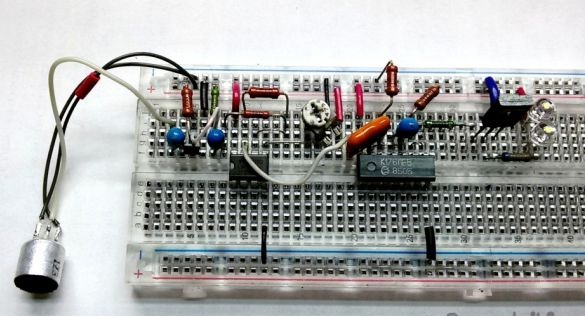
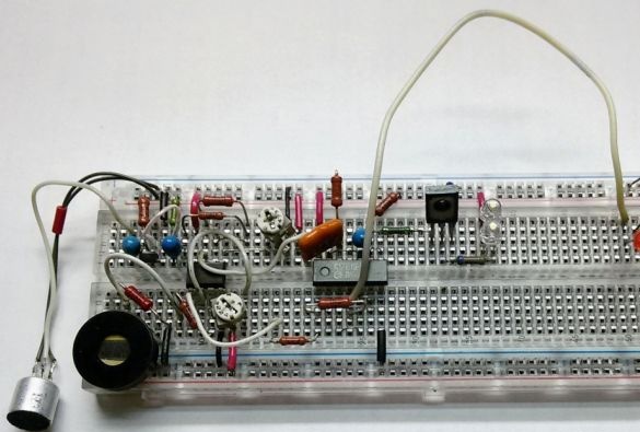
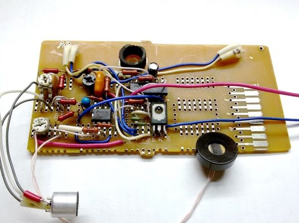
2. We place and install the parts on the circuit board in accordance with the diagram. We mount, check and debug the operation of the acoustic relay, together with the output transistor and LEDs as an indicator of the operation of the device.
To check the operation and debugging of the modes of this unit, we connect conclusions 8 and 9 of D1.4. Set the microphone mode. Using R8, we set the current through the microphone to about 200 microns and the voltage on it is 1.6 volts. Using R14, we set the reference voltage at input 5 of DA1.2 to about 1.5 volts. When an acoustic signal appears, the LEDs should light up. In order to save battery, connect the device to a network power source.
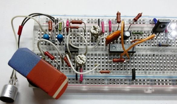
3. Mount the photo relay circuit. Using R2, the sensitivity of the photo relay is adjusted. The resistor R4 sets the reference voltage at input 2 of DA1.1 of the operational amplifier LM358. To check the state of the logic element of the microcircuit, when debugging the operation of the device, it is convenient to apply an additional chain - 1k resistance and an LED (on the photo to the right).
4. We check the operation of the device as a whole. Connect the terminals 8 DD1.4 and 4 DD1.2. Check operation with open and closed photoresistor.
5. We connect the power source with which the device will work. Check the operation of the device.
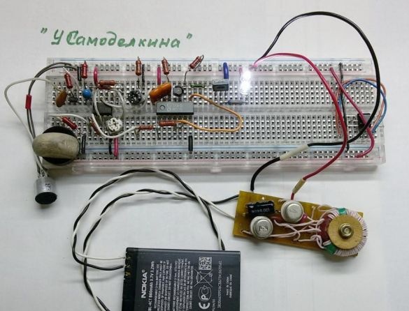
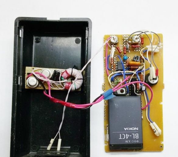
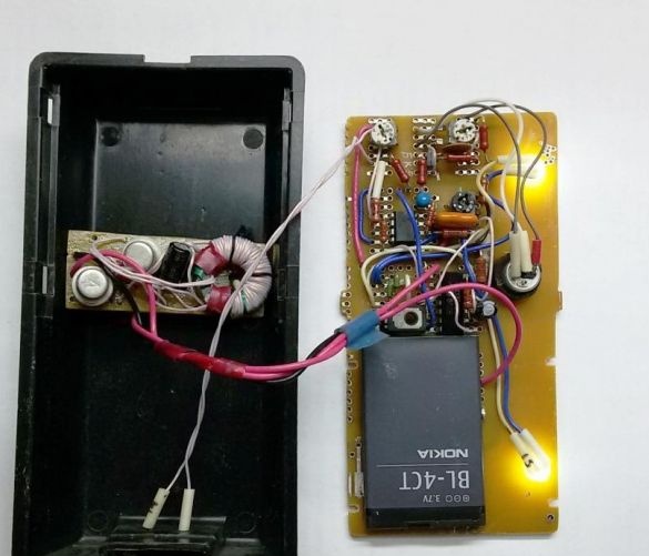
Since it is planned to operate a nightlight from a Li-Ion battery for a mobile phone with a voltage of 3.7 volts, a simple and economical step-up DC-DC converter from 4 to 7 volts was made to coordinate the voltages.
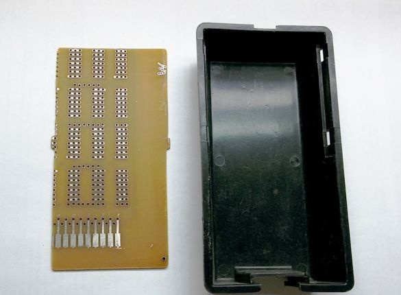
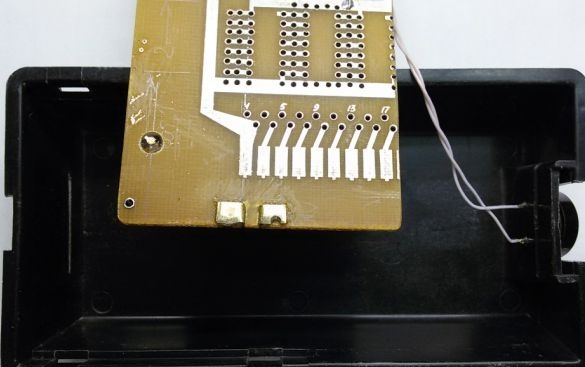
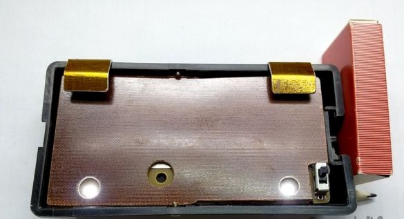
6. We select the appropriate housing for the device. A plastic box was found in the farm, which will house all the nightlight components. According to the internal dimensions of the box-case, from the universal board, a mounting plate (63x122 mm) is cut out.
7. Details of the debugged circuit from the circuit board are soldered to the working board. This leaves free fields for the placement of LEDs, a microphone and a battery.
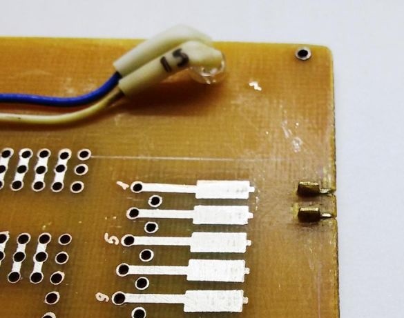
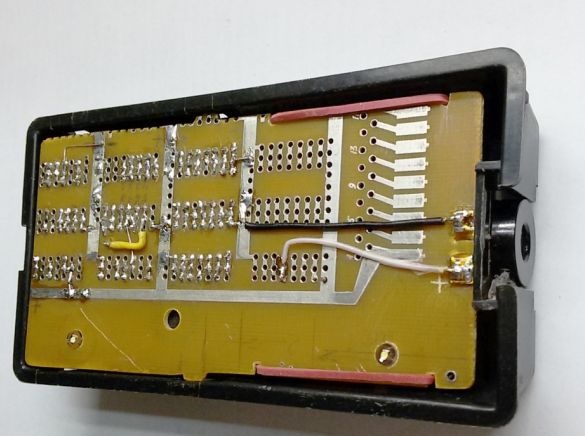
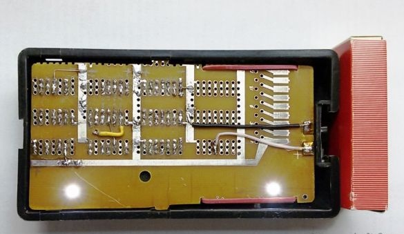
8. Under the battery terminals, in the board, two slots are marked and cut into which the L-shaped brass contacts are glued.
9. A photoresistor is installed in the groove on the outside of the case. The microphone and LEDs are installed in their places.
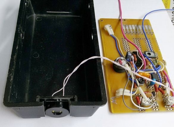
10. We assemble and test the entire structure.
11. In addition, we install a textolite shield in the device to protect the board contacts, a slide power switch and aluminum hooks for installing the night lamp on the clock.
12. Set the nightlight in working position ...

... and say the magic word (of your choice).
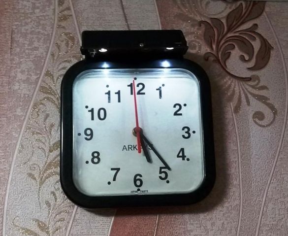
After adjusting the sensitivity limit, the backlight turns on only in an unlit room.
The proposed acoustic switch does not require an external power source, is assembled from common parts, has a simple circuit and good sensitivity (responds to a signal within the room).
This design of the night lamp, for versatility of use, is made in the housing. But its circuit can also be assembled on the back side of the wall clock, while the details of the nightlight will not be visible until it is turned on.
This circuit is tested in practice, it works stably with a supply voltage of 6 to 9 volts, so choosing a power source is not difficult. You can use "Crona" or other batteries and rechargeable batteries. If you need to power the device from the network, then on the Internet there are many schemes of power supplies, of various designs and complexity.
This switch can be used not only as a night lamp, but also for turning on / off (for example, clap or voice) other electric devices, including more powerful ones (turning on the intercom, floor lamp, desk lamp or lighting in the hallway, security system, etc.) .d.). Everything will depend on the design of the power supply and a simple actuator, added to the output of this circuit.
The K176LE5 chip can be replaced with the K561LE5. Resistors and capacitors can be any small. Instead of the specified photoresistor, you can use others that are similar in characteristics. The LED is replaceable with any one with high light output. The power battery may be composed of galvanic cells or small batteries connected in series.
The schematic diagram of the night light is quite simple and there is no need to configure it after its correct assembly.
To prevent false triggering of the night light, it is necessary to provide protection for the photoresistor from the light of the LEDs that are turned on. When any light hits the photoresistor, the LEDs immediately go out. To ensure the nightlight works in real conditions, it is advisable to direct the photosensor towards the window - the source of natural light.