» Topics » DIY ideas »Radio Relay or How to Become a Magician

Radio Relay or How to Become a Magician


As often happens during repairs (and sometimes even in an apartment) - they did not think of how many outlets and which switches would be needed for comfort. Sometimes you can add the missing communications, and sometimes it already leads to additional waste and redoing part of the repair. As an output, you can use a radio relay with remote control.

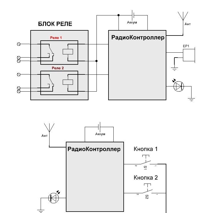
General scheme of Radio Relay:


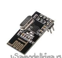
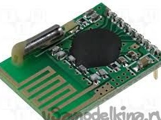
For communication between the Radio Button and the Radio Relay, radio modules are used:
- nRF24L01
Radio Relay or How to Become a Magician

- RMF73


The controller used Attiny2313, also tested Attiny45.
Transmitter Circuit:

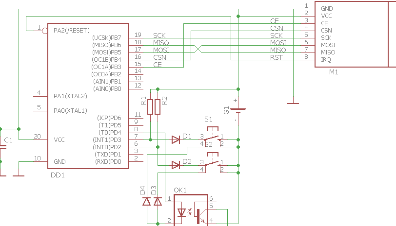
When a button is pressed, the minus of the battery closes to the ground, thereby powering the controller and at the same time a logical “0” appears at the input of the corresponding one of the buttons. Further, the controller, recognizing the press of a button, feeds the optocoupler “1” to the input, thereby closing the minus batteries to the ground, which will allow it to remain connected to the power when the button is released. Having completed the data transfer, he will remove the voltage from the input of the optocoupler, thereby disconnecting.
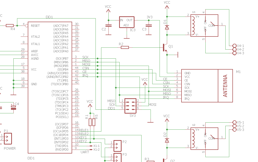
Receiver circuit:


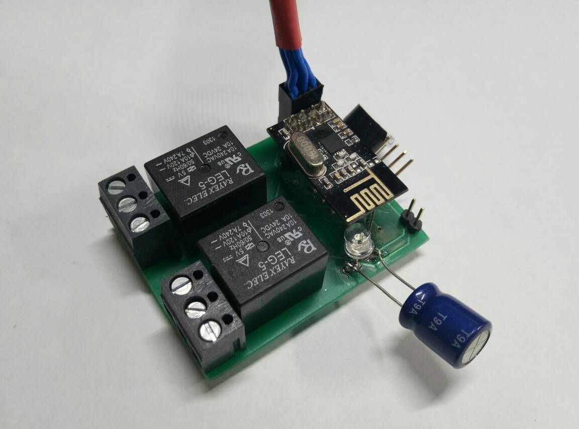
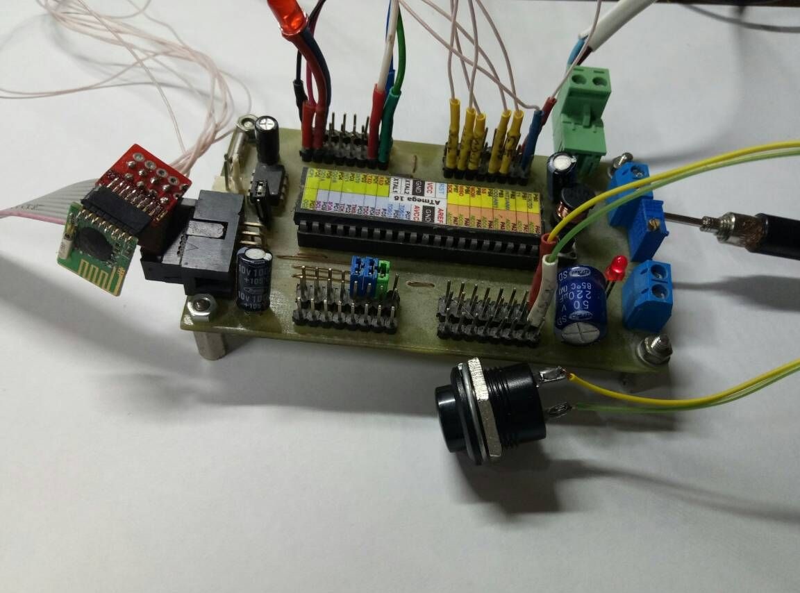
View at the development stage:


Schemes in Eagle 7.6 format sch.rar [72.96 Kb] (downloads: 42)
Question \ topic is automatically published in the social. site network - stay tuned for answers there:

Suitable for topic

Related topics

Add a comment

    • smilesmilesxaxaokdontknowyahoonea
      bossscratchfoolyesyes-yesaggressivesecret
      sorrydancedance2dance3pardonhelpdrinks
      stopfriendsgoodgoodgoodwhistleswoontongue
      smokeclappingcraydeclarederisivedon-t_mentiondownload
      heatirefullaugh1mdameetingmoskingnegative
      not_ipopcornpunishreadscarescaressearch
      tauntthank_youthisto_clueumnikacuteagree
      badbeeeblack_eyeblum3blushboastboredom
      censoredpleasantrysecret2threatenvictoryyusun_bespectacled
      shokrespektlolprevedwelcomekrutoyya_za
      ya_dobryihelperne_huliganne_othodifludbanclose
5 comments
Author
Really...
Quote: mj2link
As far as I see battery power only at the transmitter

We are apparently looking at different schemes. On those that I see, both on the structural and on the circuit diagrams, the receiver does not have power from the network.
Author
Yes RMF73! typing error.
Thanks.
Author
As far as I can see, battery power is available only at the transmitter and it only works for a short period when transmitting after pressing a button (in my kitchen, after unknown reasons, a wire embedded in the wall burned out somewhere, such a unit was installed. It has been working for 2 years now 18650 battery). And the relay is in the unit where the voltage of the controlled product is switched, which entails power from the same source.
Thanks.
RMF73
Not RFM73?

The device in the presented form is not very suitable for the purposes you stated: powering the relay windings from the battery leads to the need to often charge it. If you apply for something that is not very often and does not turn on for long, then it will do.

We advise you to read:

Hand it for the smartphone ...