

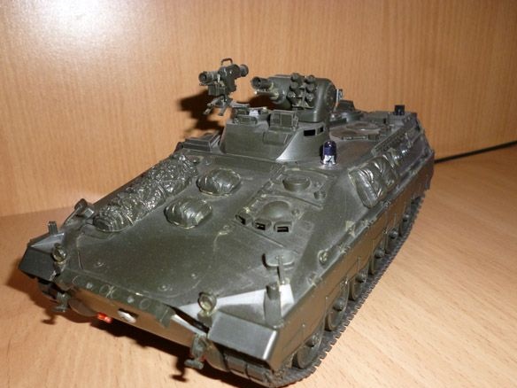
Good afternoon, today I want to share instructions on making a tank. There will be two options for the internal controller: ESP -8266 and Arduino Pro Mini. In the first version, control is carried out via Wi-Fi communications. In the second - IR remote. It is made on the basis of the TAMIYA 35162 Schutzenpanzer Marder 1A2 (1:35), it is driven by a Tamiya 70097 Twin-Motor Gearbox Kit and the motors that came with the gearbox.
We will need:
- TAMIYA 35162 Schutzenpanzer Marder 1A2 (1:35)
- model glue (TAMIYA Cement for example)
- Tamiya 70097 Twin-Motor Gearbox Kit
- ESP 8266 -12E or Arduino Pro Mini 8MHz 3.3V
- voltage stabilizer AMS 1117 3.3v 8000mA (if option with ESP 8266-12E)
- Qifei L9110 engine driver
- capacitor 10v 1000uF
- two-color (red, green) LED
- blue LED
- 2 red LEDs
- IR receiver
- photoresistor
- 2 compartments for 2 AAA batteries or 4 AAA 1.2V 1000mA NI-MN batteries
- 2 resistors 2ohm
- 4 resistors 75 ohms
- 6 resistors 10 kOhm (if option with ESP 8266-12E)
- button
- photoresistor
- USB - TTL
- soldering iron
- multi-colored wires
Step 1 Housing and mechanics.
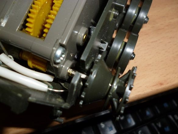
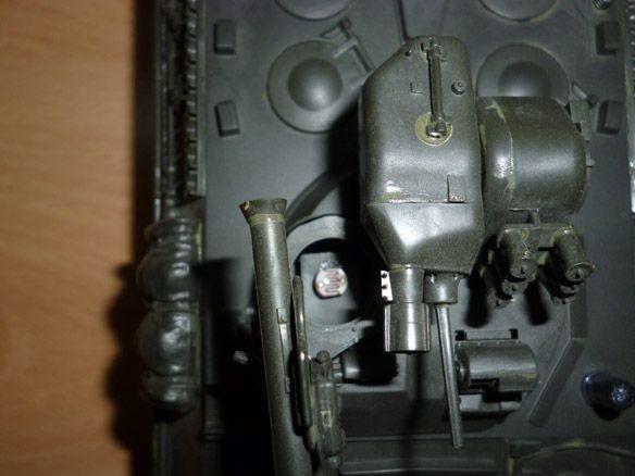
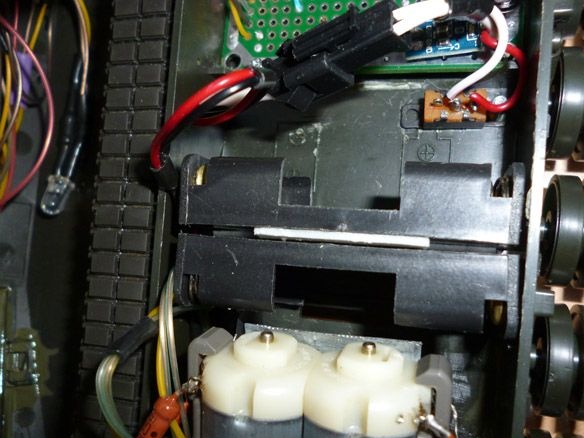
First you need to collect model TAMIYA 35162 Schutzenpanzer Marder 1A2 (1:35). We glue the lower part according to the instructions, with the exception of the parts covering the outlet openings for the gearbox shafts. Leading stars also do not stick. Glue the upper part according to the instructions without changes. Having glued all this, leave for drying and proceed to the collection of the gearbox. As can be seen from the instructions Tamiya 70097 can be assembled in two different versions.
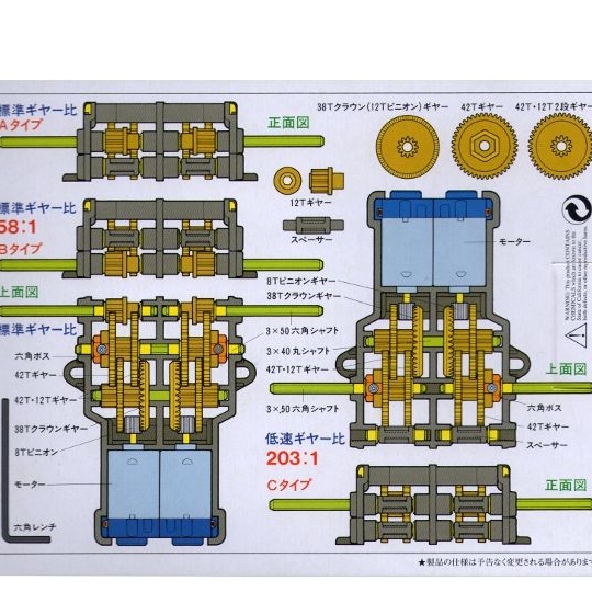
The first option with a gear ratio of 58: 1, the second - 203: 1. We need the first option. And here, too, is not so simple. In this case, the axis output may be closer to the bottom of the gearbox or in the middle. Axes must be exhaled into the middle hole! Having assembled the gearbox, we proceed to install it on the model. In theory, everything should be simple, because both the model and gearbox of one firm. In practice - the gearbox had to be pushed there. In the horizontal position of the gearbox, the shafts of the drive wheels bulged upward, so we had to cut a metal plate, which made it possible to fix the gearbox in the desired position.
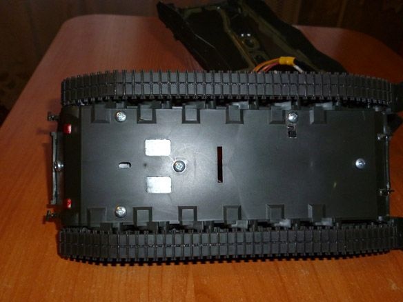
The gearbox axles will have to be cut by 3 mm. Then glue the drive wheels on them.
In the upper part closer to the back, we make holes for a two-color LED and an IR receiver.
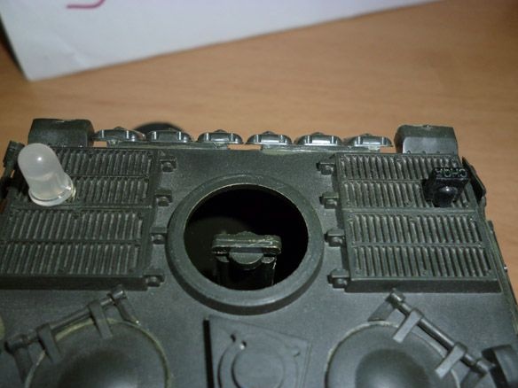
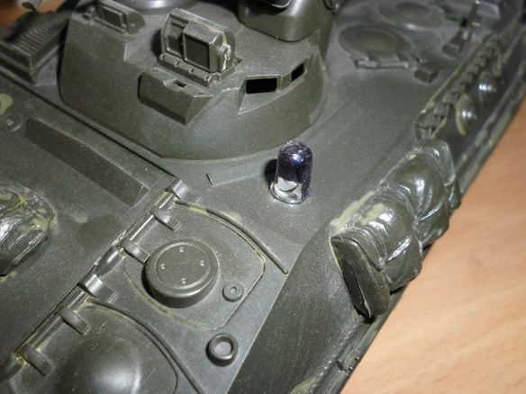
Closer to the front is a hole for a blue LED that will serve as a flashlight.
And inside the hatch - for a photoresistor.
On the reverse side, glue the red LEDs for illumination.
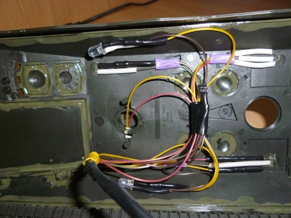
To all the above, you need to solder the wires. It is more convenient to do this before installation.
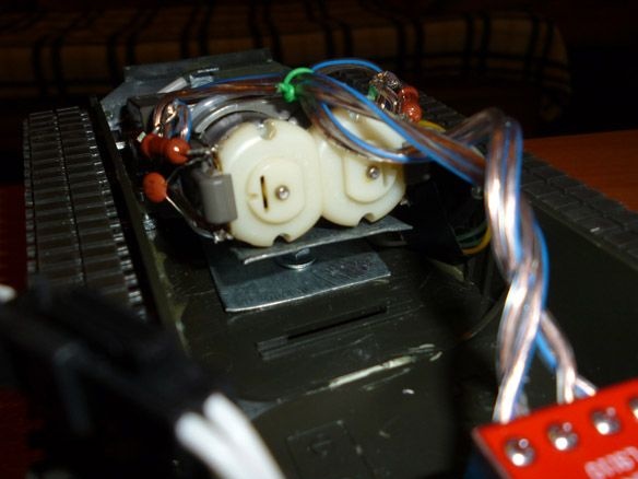
Step 2 Electrician
Here I will provide a choice of options for further assembly.
If you have chosen ESP 8266. The built-in Wi-Fi module greatly facilitates the process of control and connection.It can be easily programmed in the Arduino IDE. It is best to choose a module with 4 Mb of memory. In this case, it is necessary to collect the minimum harness to start and flash the ESP-8266. Only the VCC pin is connected directly to the power supply, the remaining pins: CH_PD, RESET, GPIO0, GPIO2, must be pulled to the power supply (VCC) via a resistor. 10kOm resistors can be replaced with others, from 4.7kOm to 50kOm, except for GPIO15 - its value must be up to 10k. Directly, to the minus (GND) of the power supply, we connect only GND, and we also pull the GPIOO through the resistor to 10kOm, to put the module into the firmware download mode, to GND. The button is needed for rebooting and flashing the module. USB-TTL connector - for firmware.
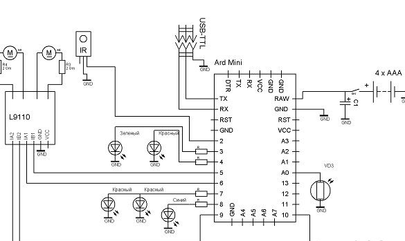
Here is a diagram
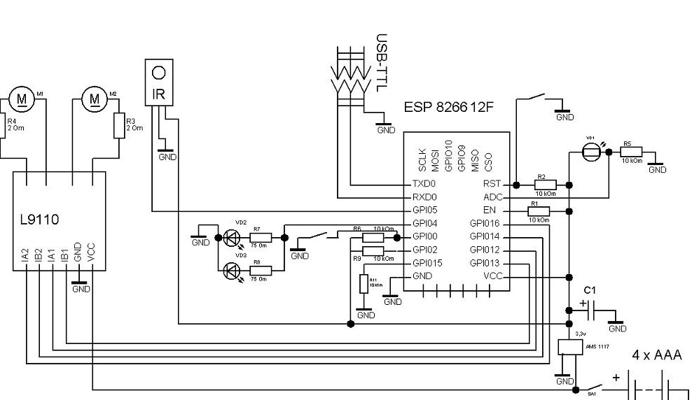
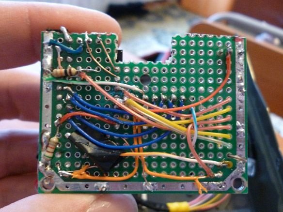
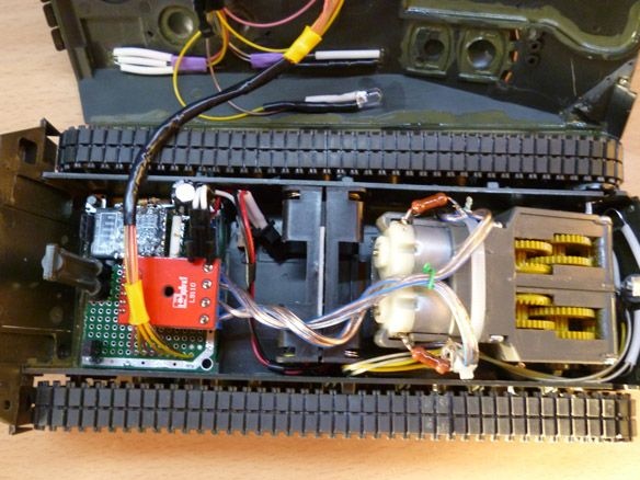
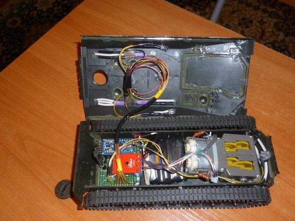
I’ll explain a little, the blue and two red LEDs are needed for backlighting (it’s visible and beautiful in the dark), the photoresistor is connected to the ADC of the controller and is needed to determine the lighting (when the backlight turns dark). 10 kOhm pull-up resistors, 75 Ohm for LEDs, 2 Ohm current-limiting for motors (without them, when trying to move, the controller overloaded). We solder everything according to the circuit on the circuit board. For power supply, you can use 4 "little" batteries or four AAA size batteries, soldered in series. We glue two compartments of two batteries with double-sided tape and connect in series. Both battery compartments and accumulators are placed between the gearbox and the circuit board.
If your choice fell on the Arduino. Only Arduino Pro MINI fits inside. It is worth choosing a 3.3 volt board, since the motors are designed for 3 volt power, and you do not want to separately power the motors and Arduino. Arduino is easier. The entire controller harness and voltage regulator are already on the board itself. It remains to unsolder the Arduino socket and motor driver on the circuit board.
Step 3 Preparing the programming environment.
To edit the firmware and fill the sketch in ESP, you need to install the Arduino IDE from the official site of Arduino.cc, as well as install the add-on for ESP, through the Boards Manager. To do this, start the Arduino IDE, then File - Settings - in the Additional Boards Manager URLs field, insert the link
http://arduino.esp8266.com/package_esp8266com_index.jsonclick OK (you can enter several links separated by a comma in this field). Next Tools - Board - Boards Manager in the filter field, enter esp8266 and click on ESP8266 by ESP8266 Community Forum. Click Install and wait for the download to finish. Now it remains to select the Board - Generic ESP8266 in the Tools menu and set the frequency of your module to 80 or 160Mhz, size of flash memory and select the serial port to which the USB-TTL adapter is connected.
For Arduino, just install the Arduino IDE from the official Arduino.cc website.
Step 4 Firmware
It remains to edit the sketch and fill it with ESP.
In the field "String _ssid =" ";" between quotes indicate which access point you want to connect to.
"String _password =" ";" is the password for this network.
"String _ssidAP =" Mardella ";" the name of the network that the ESP will raise if it does not connect to the existing one.
"String _passwordAP =" 12345678 ";" - the password of the network that the ESP will raise if it does not connect to the existing one.
"String SSDP_Name =" Mardella ";" SSDP name
After starting, ESP tries to connect to the access point specified in the sketch, if successful, you need to determine the IP address of our robot and connect to this address through a browser. You can also go through a computer to the network infrastructure, find our tank there and double-click to connect to it. If the connection fails, the ESP becomes the access point. Then access can be obtained by connecting to a new access point and entering 192.168.1.1 in the browser.
The web interface consists of two pages. The first to control. The second is for customization. On the second page, you can specify the access point to which you want to connect, as well as the name of the tank and the name and password of the access point that the ESP raises. All changes take effect after a reboot. You can also restart the module via the web interface.
For Arduino, you need to edit all the “results.value” fields. Having written down the IR codes of the console that you are going to use there.
Video tanchika: