List of what we need:
- Digispark Attiny85
- Oled display 128x64 I2C
- ds18b20 temperature sensor
- Resistor 4.7 Kom 0.25 W
- ISP programmer or Arduino Digispark Attiny85 firmware board
- Plastic tablet with paper clip or sheet of thin plastic
- wires
- Dupont 2.54 mm “female” connectors
- Buttons 2 pcs.
- Small circuit board or small trim
- soldering iron
- Solder, rosin
- scissors
- clerical knife
- Hot glue gun
- Hot glue
Step 1 Selecting Components.
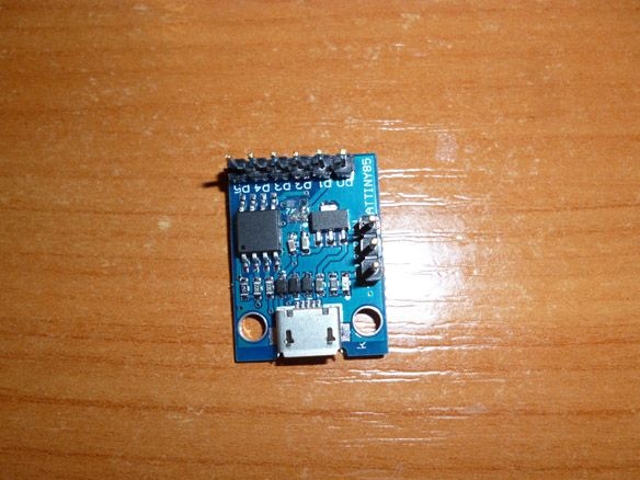
As the main controller we will use Digispark Attiny85. There are several types of them. We need a board with a micro USB connector. The rest will not fit in the watch case.
To display, we need an Oled 128x64 I2C display. They come in different colors: white, blue, blue with yellow. Draw your attention! The term “two-color” in the description or title of this screen means a strip of one color at the top of the screen and the second color the entire remaining screen, and not the ability to display two colors with this screen! All screens of this type display only one color, or at the top a strip of one color at the bottom - another. Like, for example, the one that I will use. The bar above is yellow; the rest of the screen is blue. You can choose any color you like.
We also need the integrated temperature sensor DS18B20. It was not chosen by chance. First, the DS18B20 communicates with the microcontroller via a single-wire communication line using the 1-Wire interface protocol. In our case, this is important, since the conclusions of Attiny85 without a sensor are few. Secondly, this sensor is a digit, that is, it takes all the measurements itself and simply transmits temperature data without spending the computing resources of Attiny85.
As for the rest, I think there will be no questions, so let's move on to manufacturing the case.
Step 2 Assembly of the housing.
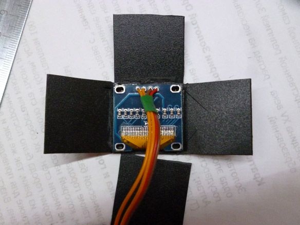
The watch case will be made of thin plastic. I had a plastic tablet with a paper clip on my hands. It is tough enough to hold its shape, and at the same time it can be cut with ordinary scissors and an office knife. He came up perfectly.If it is not at hand, you can buy a tablet in an office supply store or find the right plastic to replace the tablet. We make markings on plastic according to the scheme:
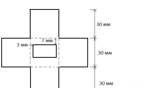
Cut out all the solid lines. Dotted - slightly cut with a clerical knife. Dotted lines are fold lines. As you already understood, this is the usual cube layout. Next, you need to solder the wires to the screen, it is best to take multi-colored and write down which leads to what. Glue the screen on the hot-melt adhesive in the middle, so that the front side it exits from the back. As you can see, we have closed the screen pin designations. Therefore, it was necessary to write them down. I slightly handed over to the knife, and thereby cut off the lower part of the body. There is nothing wrong with that, everything can be glued. But it’s better not to repeat my mistakes.
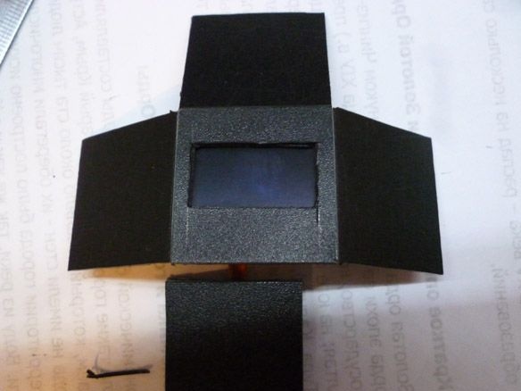
The result should be like this:
On this case is ready. You can still cut the back cover out of the same plastic, but this is optional.
Step 3 We solder.
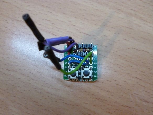
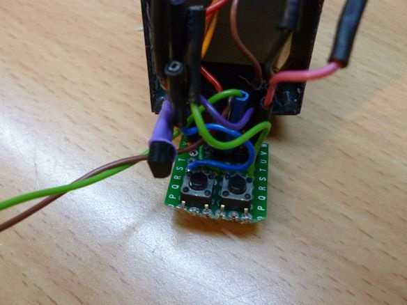
Our case is small, and we have to cram a lot there. Therefore, we take a piece of the circuit board no larger than 2.8 x 2.8 mm and solder in two buttons, a ds18b20 sensor, a resistor and several contacts. According to the following scheme:
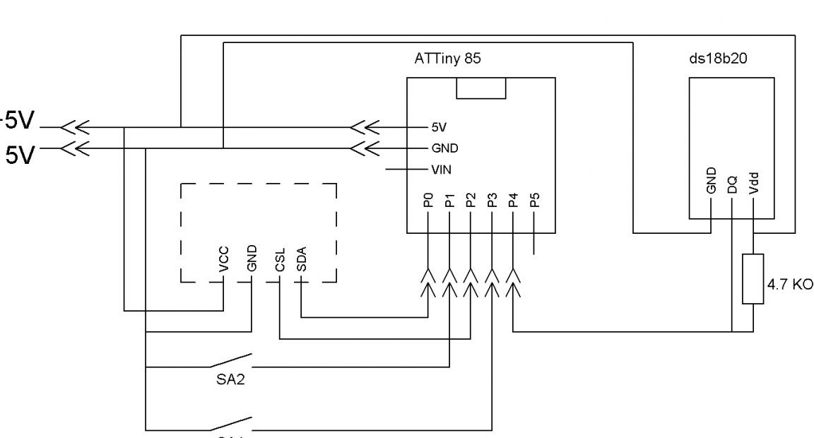
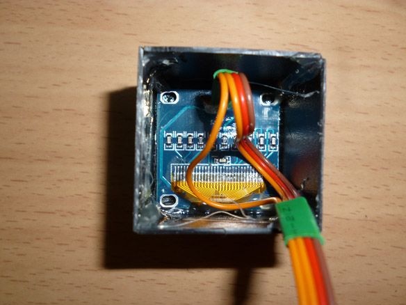
It’s not necessary to solder wires directly to Attiny, since it is necessary to disconnect everything for firmware. The result should be something like this:
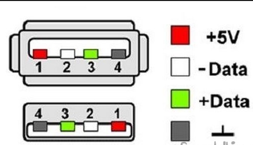
Buttons are needed to set the time. Power can be taken from the USB port of the computer. Combining the plus and minus, respectively:
If you want to do without wires, you need to find a small lithium-ion battery. Here's one, for example:
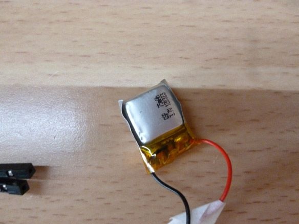
This battery fits inside the case. It is only necessary to provide conclusions for the battery charge.
Step 4 Preparing the programmer.
Digispark Attiny85 can be programmed through the micro USB connector on the board, using the Arduino IDE as the programming environment. But at the same time you have to sacrifice 2 KB of memory for the bootloader. Attiny 85 has a total of 8 KB Flash. My sketch does not fit with the bootloader, so I need to program through the ISP programmer. I do not have such a programmer, but there is an Arduino Uno board, which I will use as a programmer. If you have an ISB programmer, you can skip this item. Open the Arduino IDE and fill in our sketch called ArduinoISP into our Arduino Uno. You can find it like this File - Examples - Arduino ISP. The sketch starts with a hint on how to connect the Arduino to the programmable controller. Instead of Arduino Uno, there can be any other Arduino board.
// 10: slave reset
// 11: MOSI
// 12: MISO
// 13: SCK
Scheme of connection to Digispark Attiny85:
Arduino UNO - Digispark Attiny85
D11 - P0
D12 - P1
D13 - P2
D10 - P5
Step 5 Preparing the programming environment.
To edit the firmware and fill the sketch in Attiny 85, you need to prepare not only the programmer, but also the programming environment itself. To do this, install the Arduino IDE from the official Arduino.cc website, and also install the Attiny add-on for microcontrollers through the Boards Manager.
Launch the Arduino IDE, then File - Settings - in the Additional Boards Manager URLs field, paste the link:
https://raw.githubusercontent.com/damellis/attiny/ide-1.6.x-boards-manager/package_damellis_attiny_index.jsonclick OK (you can enter several links separated by a comma in this field). Next Tools - Board - Boards Manager in the filter field, enter Attiny and click on "attiny by David A. Mellis". Click Install and wait for the download to finish. Now in the Tools menu, select:
Board - Attiny 25/45/85
Processor - Attiny 85
Clock - internal 16
and select the serial port to which the ISP programmer or Arduino is connected as the programmer.
I tried many different libraries for working with the screen. In my opinion the most convenient and working on Attiny85: TinyOzOLED.
A temperature sensor needs the OneWire library.
Install these two libraries. You can install third-party libraries directly in the programming environment. Without unpacking the downloaded archives, in the Arduino IDE, select the Sketch - Connect Library menu. At the very top of the drop-down list, select the Add .Zip library item. In the dialog that appears, select the library that you want to add. Open the Sketch - Connect Library menu again. At the very bottom of the drop-down list you should see a new library. Now the library can be used in programs. Do not forget to reboot the Arduino IDE after all this.If that doesn’t help, simply unzip the archives into the “libraries” folder located in the folder with the Arduino IDE installed.
Step 6 Edit and fill the sketch.
The temperature sensor works according to the One Wire protocol and has a unique address for each device - a 64-bit code. Attiny resources are not enough to look for this code every time. Therefore, you must first connect the sensor to any Arduino board, fill in the sketch located in the File - Examples - Dallas Temperature - OneWireSearch menu. Next, run Tools - Port Monitor. Arduino should find our sensor, write its address and current temperature readings. We copy or simply write down the address of our sensor. Open the sketch Attiny85_Oled_SPI_Term_2, look for the line:
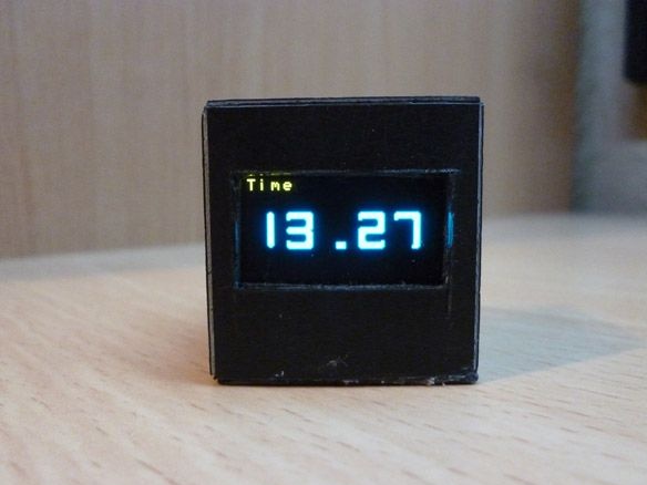
byte addr [8] = {0x28, 0xFF, 0x75, 0x4E, 0x87, 0x16, 0x5, 0x63}; We write down the address of your sensor between braces, replacing the address of my sensor. After that, connect Attiny to the programmer or Arduino as a programmer (this is described in Step 4) and fill in the sketch. It remains to disconnect the programmer and connect everything according to the scheme in 3 steps. The assembly turns out something like this:
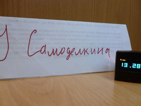
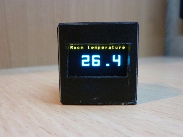
The screen is small, it is impossible to put both time and temperature so that it is visible. Therefore, the clock replaces the time with temperature readings every 10 seconds.