

We live on the edge of a small village. Faced with the need for internet at home, they began to study what modern infrastructure offers in this sense.
It turned out that the most affordable and easiest way to connect to the World Wide Web is a GSM modem, inexpensive options which are often called a USB whistle. Such a modem is inexpensive, widespread and works well, but only in the zone of reliable signal reception, the base station of the cellular network. In the city - be nice, but outside of it, it depends on how developed the mobile network is. Often a modem requires a good external antenna raised to some height. Models of devices with connectors for connecting an external antenna are considered a kind of professional communication device and cost ten times more.
For work, you will need a minimum set of radio installation and locksmith tools, a bit of patience. For working with small things, a special visor with magnifying glasses or a lamp with them is very useful. Take care of good lighting.
However, in a simple "USB whistle" inside the case there is a technological connector for the antenna and you can use it. Some modems have access to the antenna connector, some do not, in the latter case, you will have to modify the plastic case, respectively, the device’s warranty is voided. The antenna connector of the budget modem is very flimsy in design and is installed directly on the circuit board by surface mounting. That is, it holds only for rations.
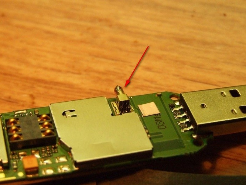
Only a sufficiently thin (flexible) coaxial cable should be connected to it, otherwise it is highly likely that the connector will be broken with a thick and hard cable. Thin cables have high RF losses and should not be used for the entire feeder. In principle, there are adapters - a modem connector - 15 ... 20 cm of thin cable - a larger connector for connecting a lower cable with an external antenna. Such an adapter allows us to solve the problem of mechanical loading on a weak connector, but we find ourselves tied to a specific connector at the output of the adapter, which is unreasonable in the case of a home-made antenna, moreover, such adapters are extremely rare on sale. It is worth remembering that each additional connector, even each soldering on the cable, introduces attenuation to the RF.
My connection option - a rather flexible television cable was picked up in the store - without a foil screen, the central core is copper (well soldered) and multi-core (flexible). The connection looked like this.
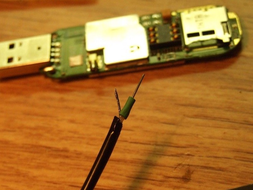
A piece of copper thick tinned wire (resistor leg) is soldered to the central core. Its thickness is such that it fits tightly into the nest. The cutting site is insulated with a heat pipe.
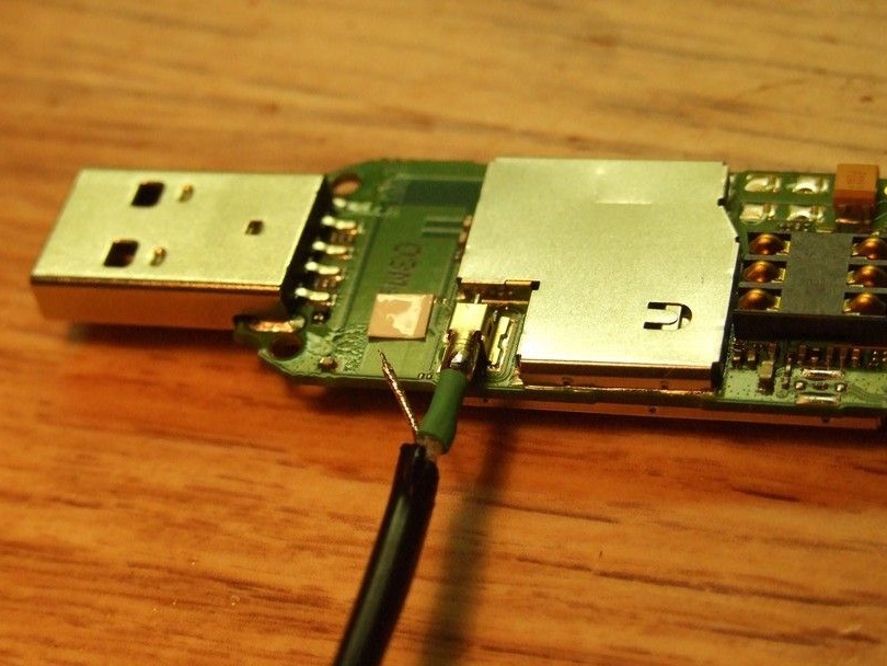
The pin is fully inserted into the connector and the twisted and tinned cable braid is soldered to the “ground” of the antenna socket.
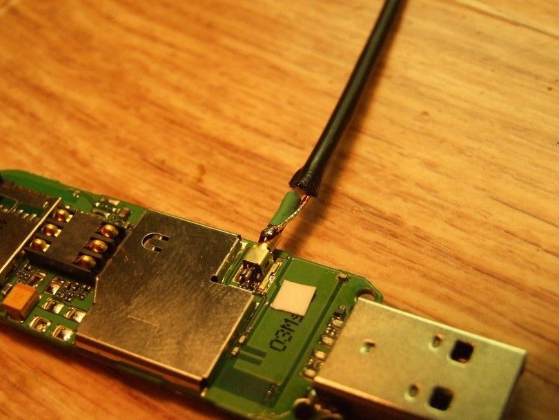
The soldering place is isolated, and most importantly, a thin spot on the cable is reinforced with several layers of heat pipe. Now it remains to try on and, if necessary, file the plastic case, so that it closes properly, with our revision. You will have to handle it carefully.
Everything, the modem is connected.
We proceed to the calculation and manufacture of the antenna.
Antenna type, selected “log-periodic”, the accepted foreign abbreviation is LPA antenna. Its features are a high gain and a very narrow (sharp) radiation pattern. In addition, with fairly accurate manufacturing, the antenna will not require tuning, which cannot be done without specialized RF measuring instruments.
You can calculate our antenna in one of the network services by finding it by keywords, or in a special program, for example Logo_Periodic_Calculate, you can find it.
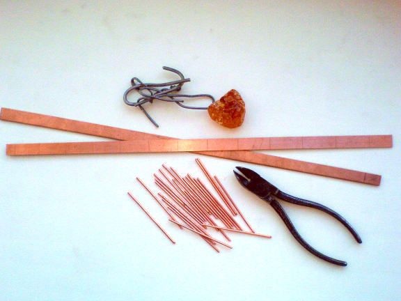
We prepare the necessary materials and tools. At the first stage, we need to cut two strips of one-sided foil fiberglass 10 mm wide, 1.5-2 mm thick, and long - according to calculations. We will also need scraps of “bare” copper wire with a diameter of 1.5-2.5 mm, which can be removed from, say, a cable for internal wiring. Well and accordingly, a soldering iron, rosin, a ruler and nippers.
We cut the elements of the same size, 5-10mm larger than the longest vibrator, referring to the calculations made. We mark the location of the antenna elements on an impromptu "boom". Next, gently solder them, without overheating the substrate, and adjust the pliers to the required sizes. It should be remembered that we are dealing with HF with its skin effect (current propagation in a thin surface layer), in this sense, “cold rations” and heavily scratched surfaces should not be allowed. A good tone is the use of a special flux with glycerin to obtain a mirror surface of rations.
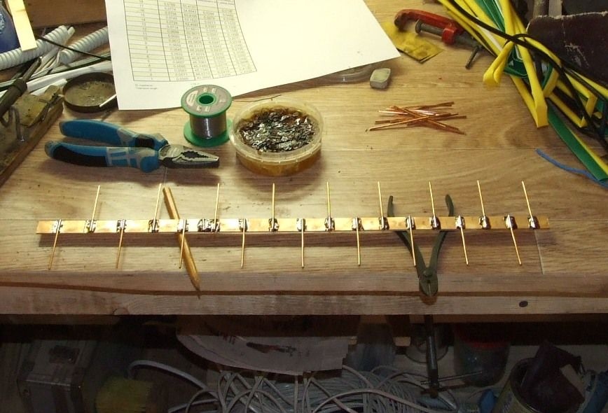
Now, you need ready-made “booms” to rigidly fix each other at the calculated distance and close the rear parts with a jumper. A coaxial cable is connected to the front ends - to one end is a central core, to the second a shielding braid.
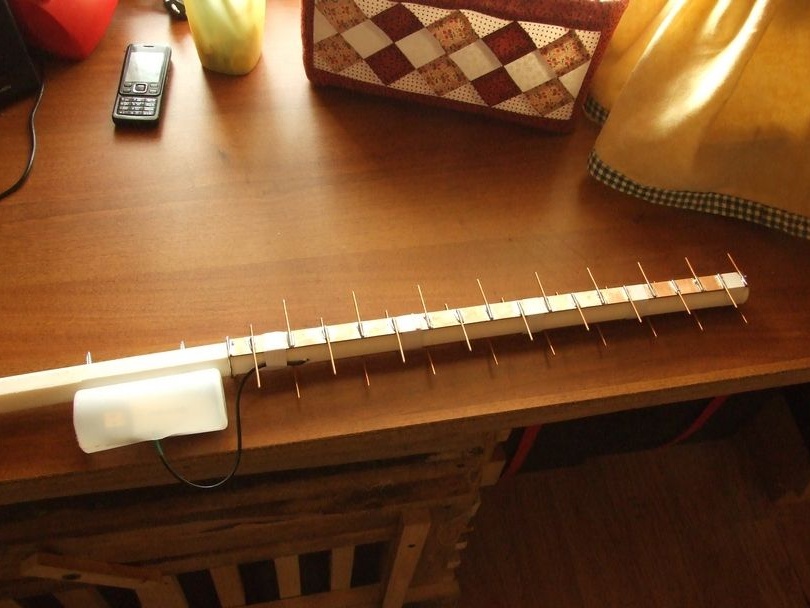
My antenna design is on a polypropylene pipe. A suitable piece of pipe was sawn on a circular saw to obtain flat areas convenient for attaching the halves of the boom. They were fastened with adhesive tape. There is a place for a modem at the back of the antenna - initially it was decided to shorten the antenna cable as much as possible, position the modem near the antenna and perform the reduction already in digital mode. The plastic pipe is taken a little longer, to obtain a convenient dielectric "handle".
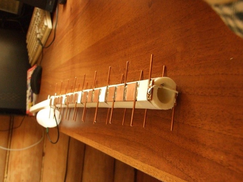
Another view of the antenna, the seats of the halves of the boom, cable connection are visible. I recommend getting acquainted with a possibly more successful antenna design.
A ready-made antenna for checking operability was taken outside and fixed at the end of a long staircase with wire.
Due to the inconvenience of orientation, I had to make a rotary assembly. A bit of locksmithing, stainless steel trimming, welding work.
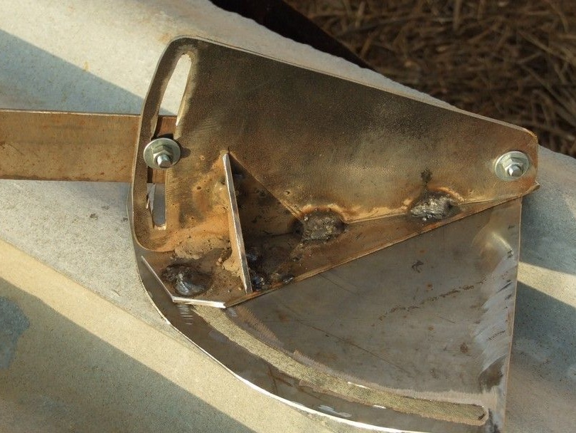
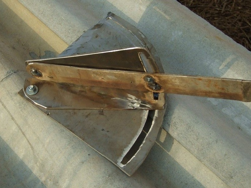
The rotary assembly turned out to be somewhat cumbersome, but unlike the similar satellite dish assembly, it is possible to orient the antenna much more accurately.
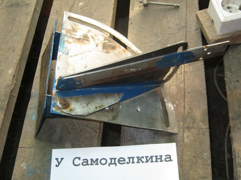
The turning unit is welded to the mount plate at an angle of slightly more than 90 degrees (so that water flows). During work, stainless electrodes ran out, the usual ones had to be used - hence the painted welding seams. In the photo above, the unit, which worked on the roof in different places, with different antennas, for about two years and generally proved to be reliable and convenient.
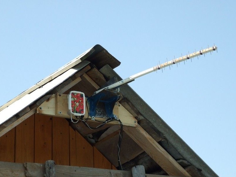
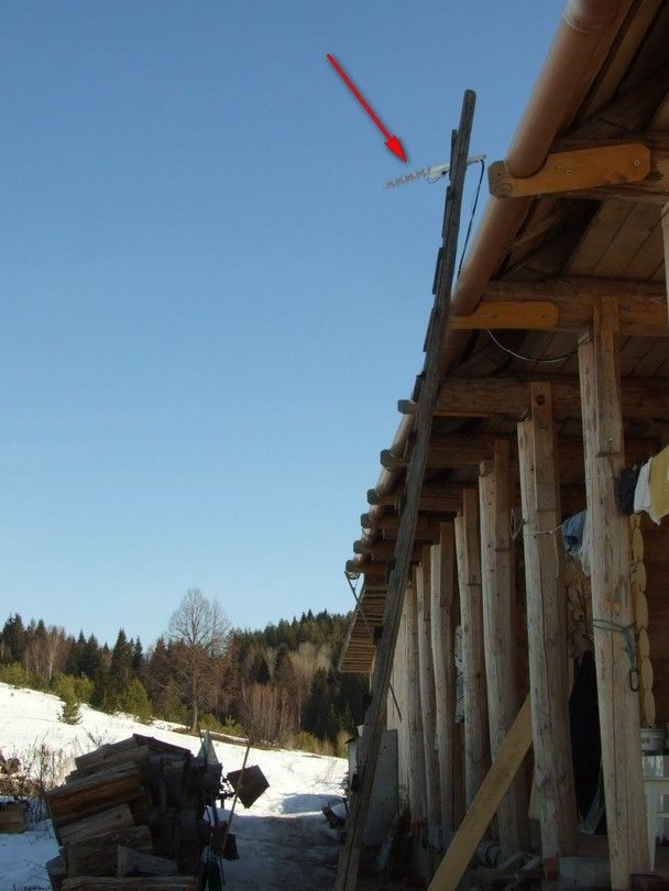
In the photo, an antenna with a USB modem is installed on the pediment of the roof. Turning angles allow you to orient the antenna to a cell tower in a neighboring village (~ 5km).

In a sealed box next to the antenna, modem and modem power supply. In general, the whole connection diagram looks like this.
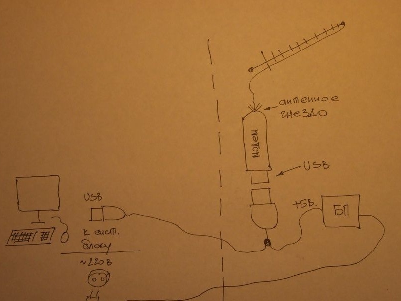
The problem with long USB connections is a drop in the supply voltage on long and relatively thin power wires (the principle of operation of the device via the USB port is including the device’s power supply from the port itself). Reasonably extending the USB cable can be done in two ways - increase the cross-section (decrease resistance) of the power conductors or power the device from its closely located power supply. The goal of both methods is to ensure that the voltage on our device is as close as possible to five volts. A plus.
The increase in the cross-section of the supply wires has already been tested during trial inclusions of the antenna “on the stairs”. The connection and access to the network were, but they did not work stably - they interrupted periodically.
To place the antenna with the turn node, another place was chosen - the pediment of the roof of the house. The distance to it is somewhat larger and it was decided to place the power supply “upstairs” - near the modem, removing the possible cause of the failures. The "long" USB connection was made of two thick coaxial cables (central cores - two data lines, screens on a common wire).
What happened - the placement on the gable of the roof (access from the flat roof of the drorovnik via a short staircase) and the general configuration of the equipment, made it possible later to conveniently experiment with different types of antennas. At that time, it was possible to connect relatively stably to the GSM (2G) network, sometimes WCDMA (3G). The antenna itself performed well. Some painstaking workmanship (many exact sizes), pays off by the lack of tuning and high gain. The antenna also has a low windage and is not very attractive to birds.
Looking ahead. The reason for the unstable operation of the modem, nevertheless, turned out to be a long USB cable, despite the well-being with the power of the device. Perhaps it was the type or even the instance of the modem, because the network comes across descriptions of such "extension cords" and a larger footage.
The manufacture and testing of two more types of antennas will be described separately.