... As I have repeatedly mentioned, my friends and I from time to time drive cars into the forest, where we live in tents for several days. This tradition has been going on for more than twenty years, and we are slowly "growing up" with things necessary for a comfortable rest in the forest. Among them is a tripod for a bonfire, which freed us from such activities as finding suitable “slingshots” and crossbeams in the forest, with their subsequent installation near the bonfire. The tripod that we acquired was of such a plan (photo from the Internet. Now is not the season, and ours is hidden somewhere on the far shelf.)):
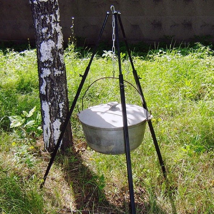
During operation, a number of disadvantages were found out, namely:
1. There is no way to quickly adjust the height of the suspension of the cauldron. (As a rule, there are no "twirls" at bonfires to quickly make the fire smaller)))) With copious boiling, there is only one thing left - to regulate the heat by raising or lowering the cauldron (boiler). To do this by hanging onto another link in the chain is good only in theory! In practice, at least two people are needed - one lifts the cauldron (and it is heavy!), The other outweighs the chain. And even for two to do it with outstretched arms above a blazing bonfire and a boiling cauldron - that’s still a pleasure!)))). In addition, if you outweigh it high, then the rest of the chain tries to dip into the boiler))).
2. Insufficient width! Our company is large, and if, for example, a fifteen-liter boiler hangs, then it should hang only at the bottom! It is impossible to lift it, since the legs narrow down from above. In order to fit high, too, the tripod must be more than two meters high ...
3. Lack of compactness. Even when folded, it is more than a meter in length! Not in any trunk goes along, or across! And if you put it diagonally - it takes a lot of useful space!
4. She can not be put aside if she is temporarily not needed! That is, I would like the tripod in the assembled state to be a rigid structure that can be put on a glove (it can be hot!) Just temporarily set aside and then just as easily put back in its place. (And with she didn’t change her geometry even if she was transferred by one “leg”) And ours, when trying to lift it, develops. (And she is hot!))).That is, it is still possible to remove and throw it aside, but now, putting it back over a blazing fire is problematic! We need to wait until the fire goes out a little.
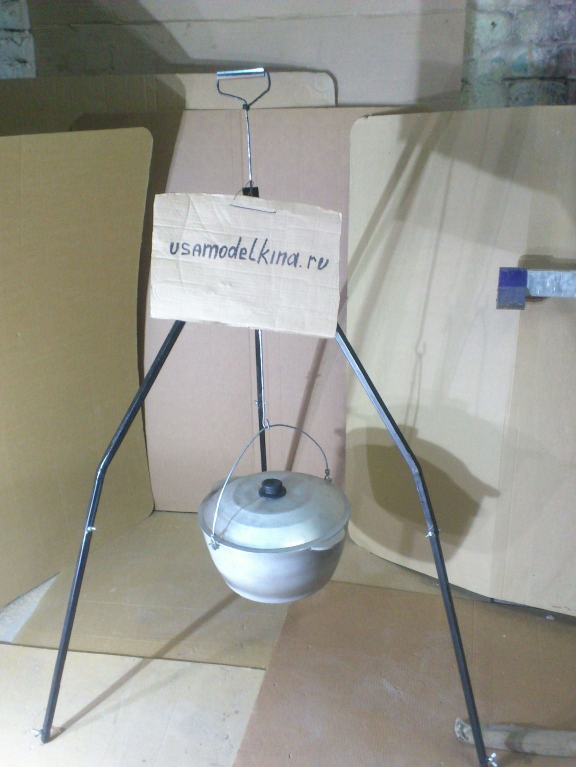
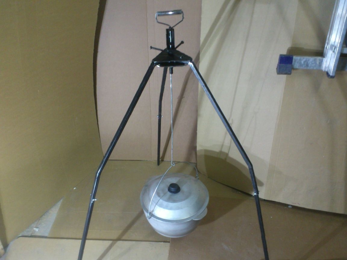
Given all these points, I decided to make a new do it yourself. And here is what I got:
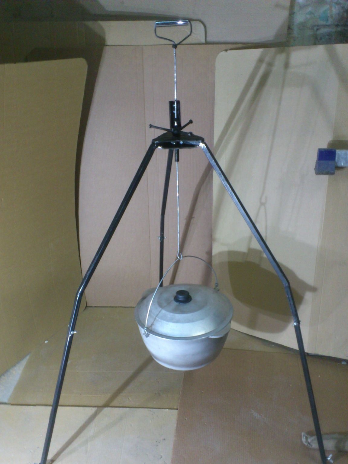
In this photo, it is not fully laid out. The lower legs are telescopic !! If you push them out, the height from the ground to the hook (in its upper position) is 1 m. 60 cm !! It's just that now is not the season for field trips and I took pictures of it in a room the size of which did not allow me to take such a massive structure into the frame.))))
Here is what I needed to make it:
1. Profile pipe with a section of 15 by 15 mm.
2. Profile pipe, section 20 on ... mm. (It is necessary for the manufacture of a U-shaped guide, so any trimming of a profile pipe with one wall of 20 mm is suitable)
3. Sheet metal with a thickness of 5 mm. (I have a “ribbed”, this is not necessary)
4. Trim stud M14.
5. square (rolled) 10 by 10 mm.
6. square (rolling) 12 to 12 mm. (It is necessary to strengthen the bending places ("bends") of the "fifteen" pipe, so short cuts will do).
7. Suspended spring element from Armstrong suspended ceiling system.
8. A wire with a diameter of 4 mm.
9.Cutting of a 16 mm ridge tube. (Not necessary.)
10. M6 bolts 25 mm long. (3 pieces for the manufacture of axes "legs")
11. Cap nuts M6. (For the same.)
12. M6 bolts wing. (3 pcs. For fixing the telescopic parts.)
13. M6 nuts. (Conventional)
14. Nuts M14.
15. Wing bolts M5 (3 pcs.)
16. Wing nuts M5 (3 pcs).
17. Heat-resistant enamel.
... I wrote this list - and myself in shock !!! After all, he did something simple, one might say, a primitive product, and a lot of names of materials were needed!

But nothing!! We're not looking for easy ways!!!
 The product has turned out, and meets all the criteria laid down by me! So - the time and effort wasted not in vain !!
So, where did I start? .. Think of a drawing? If so, then you are only partly right!

The fact is that I never draw my drawings homemade! It takes time, but it is always lacking! Besides, homemade products are my hobby! So, each product is made in a single copy! Therefore, after its manufacture, the drawing will certainly not be needed! And since God didn’t offend me with spatial thinking, I prepare all the “drawings” of home-made products only in my head! As a rule, I do it behind the wheel, where I spend a lot of time, daily spinning around the city. And I will draw individual details only already on the workpieces, before embarking on the grinder! )))) And if I need to “translate into meters”, the size I intuitively need, then I imagine the future part, holding a tape measure in my hands, looking at it, and mentally trying on the future part to it))))
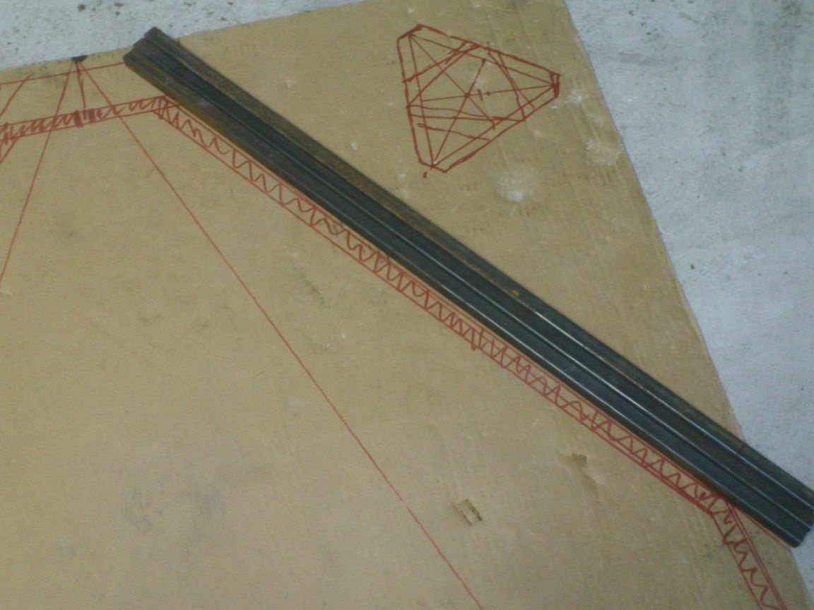
But now I still drew a little ... That is, I just drew a sketch of a tripod of the size I would like, in a scale of 1: 1 on a piece of cardboard.))).
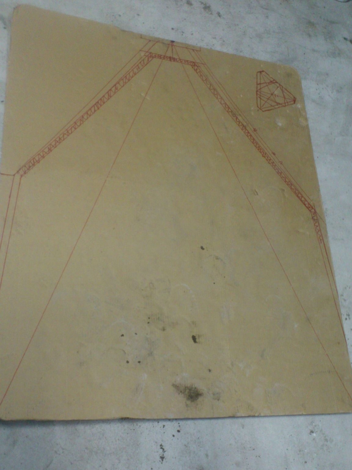
And then it's easier. Applying the blank to the sketch, I made one of the three main elements. (I started with the upper parts of the "legs").
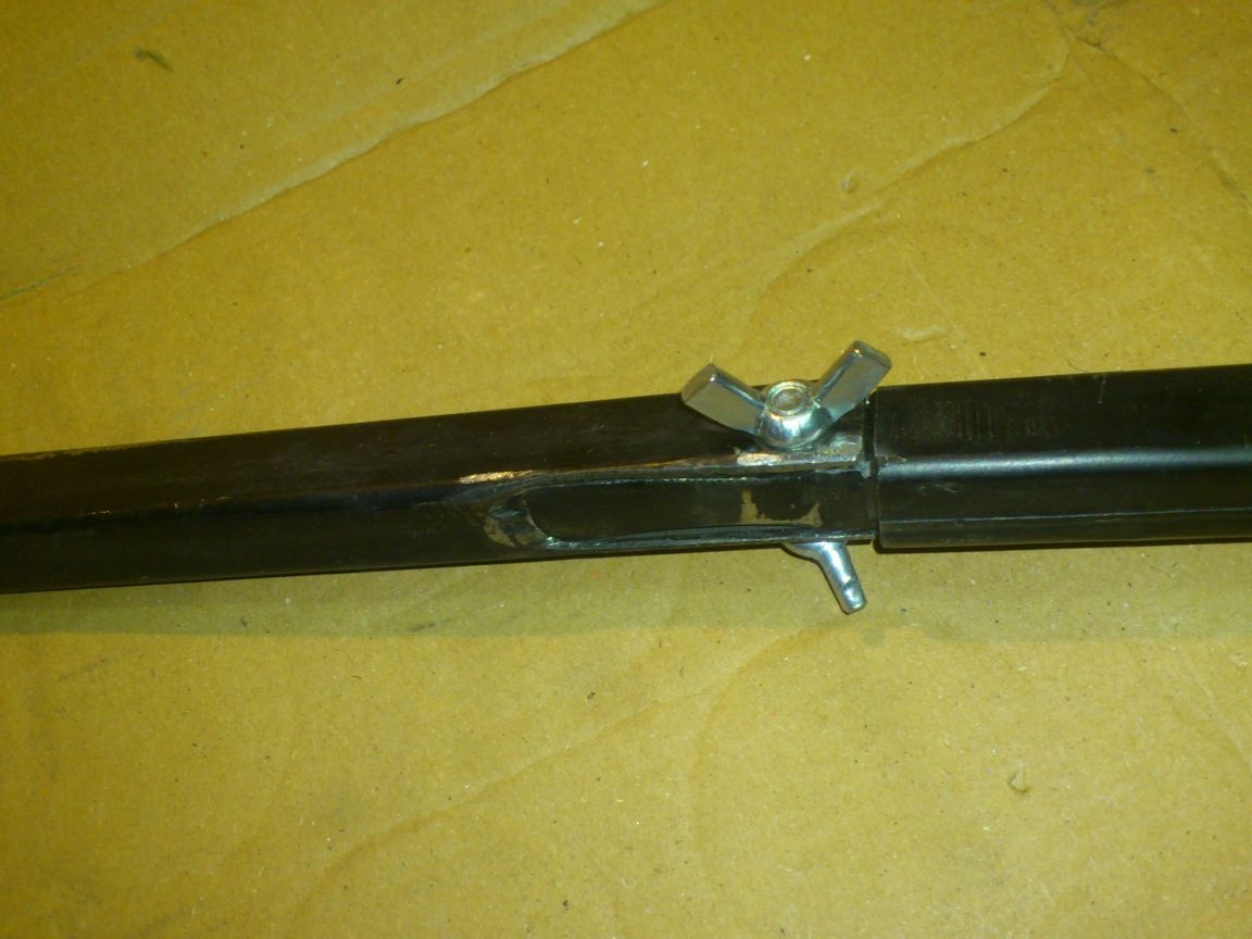
According to my idea, this part will have two short “shoulders” bent at a certain angle at the ends. The upper "shoulders" will be clad with ends on the axis, and, through them, pivotally attached to the upper plate. The upper and lower plates will be pulled together by the M14 hairpin, and the “shoulders”, being sandwiched between them, will provide a rigid fastening of the “legs” and the desired angle of their placement ...
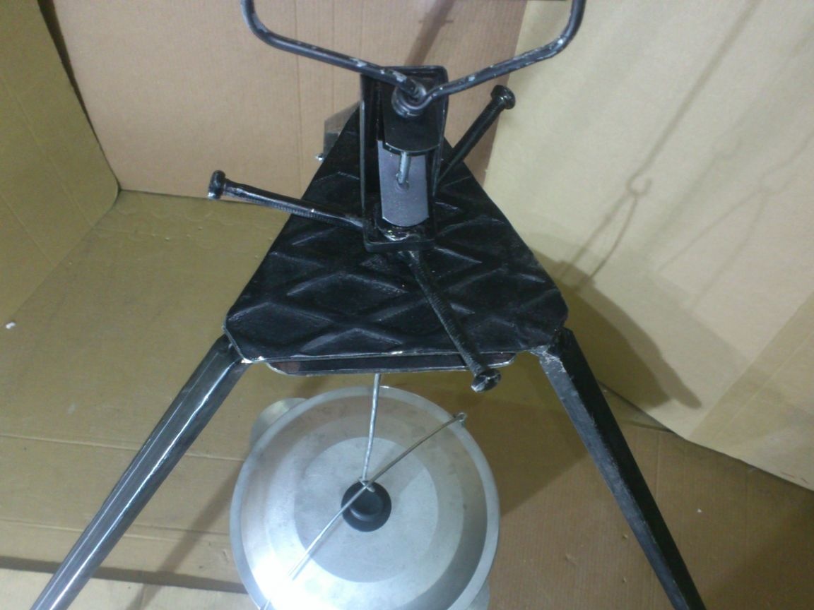
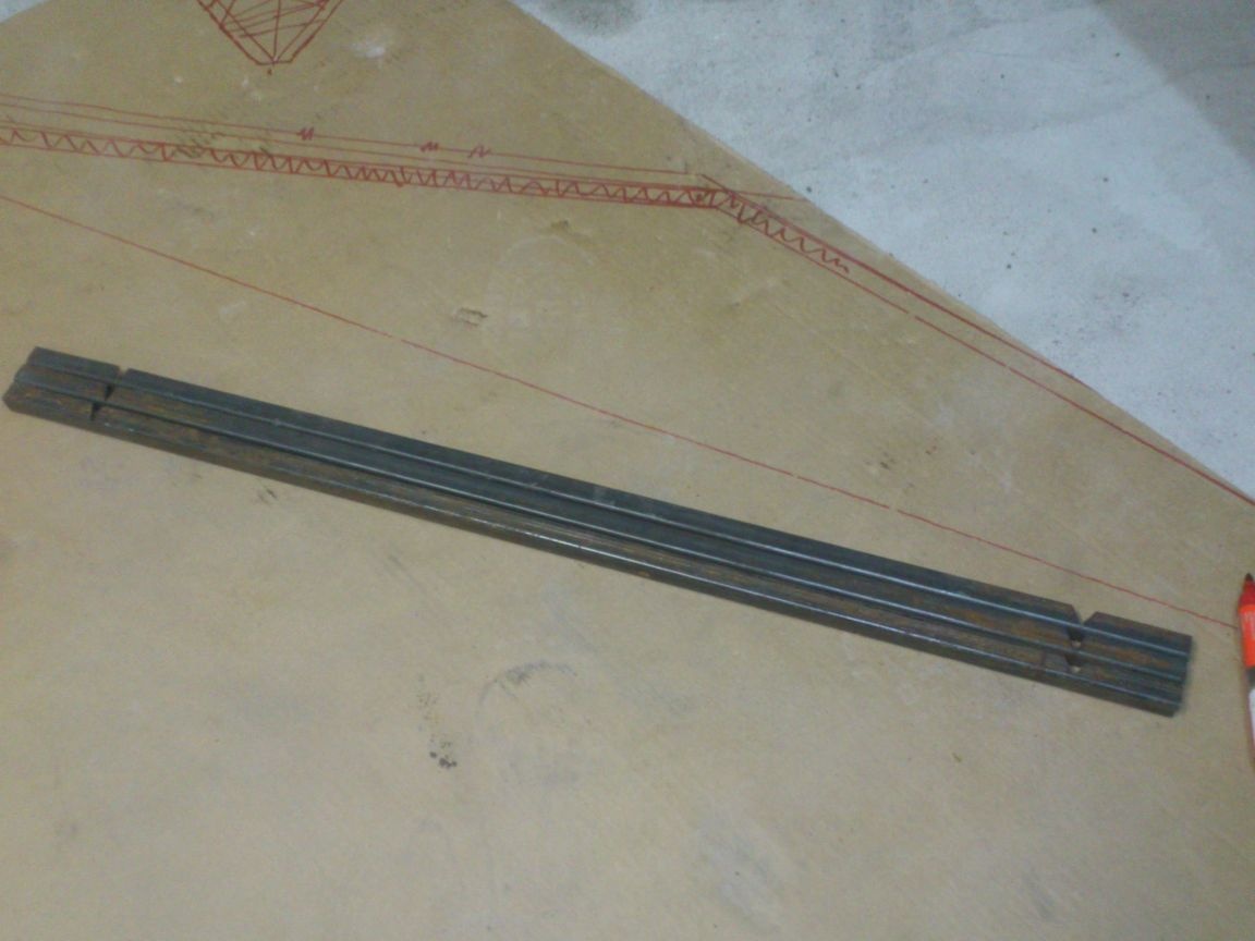
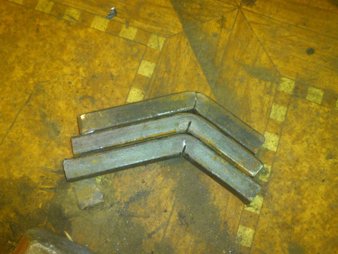
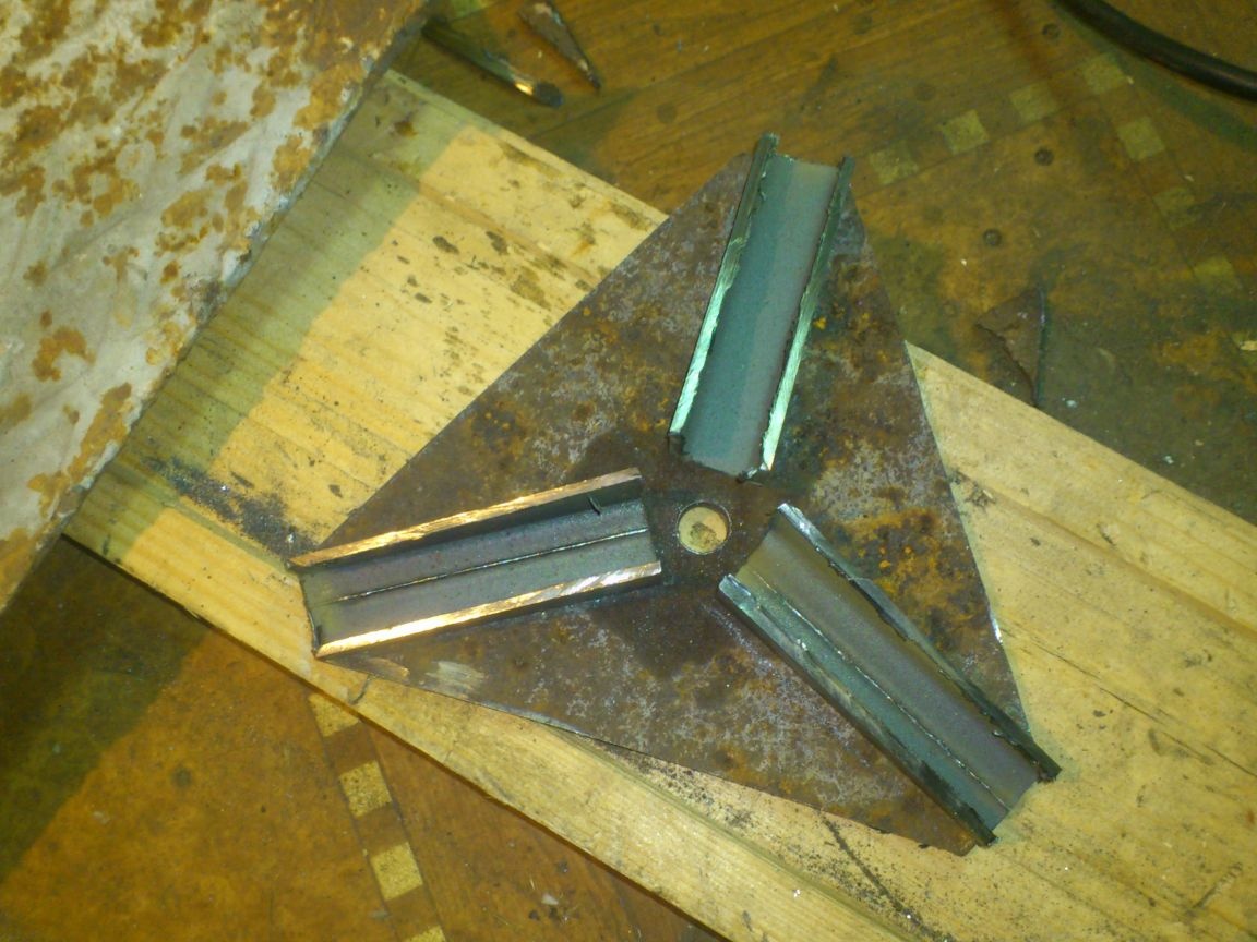
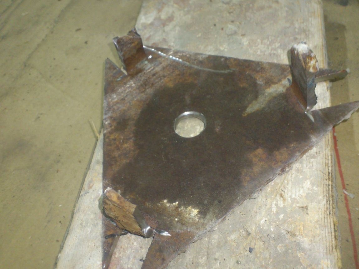
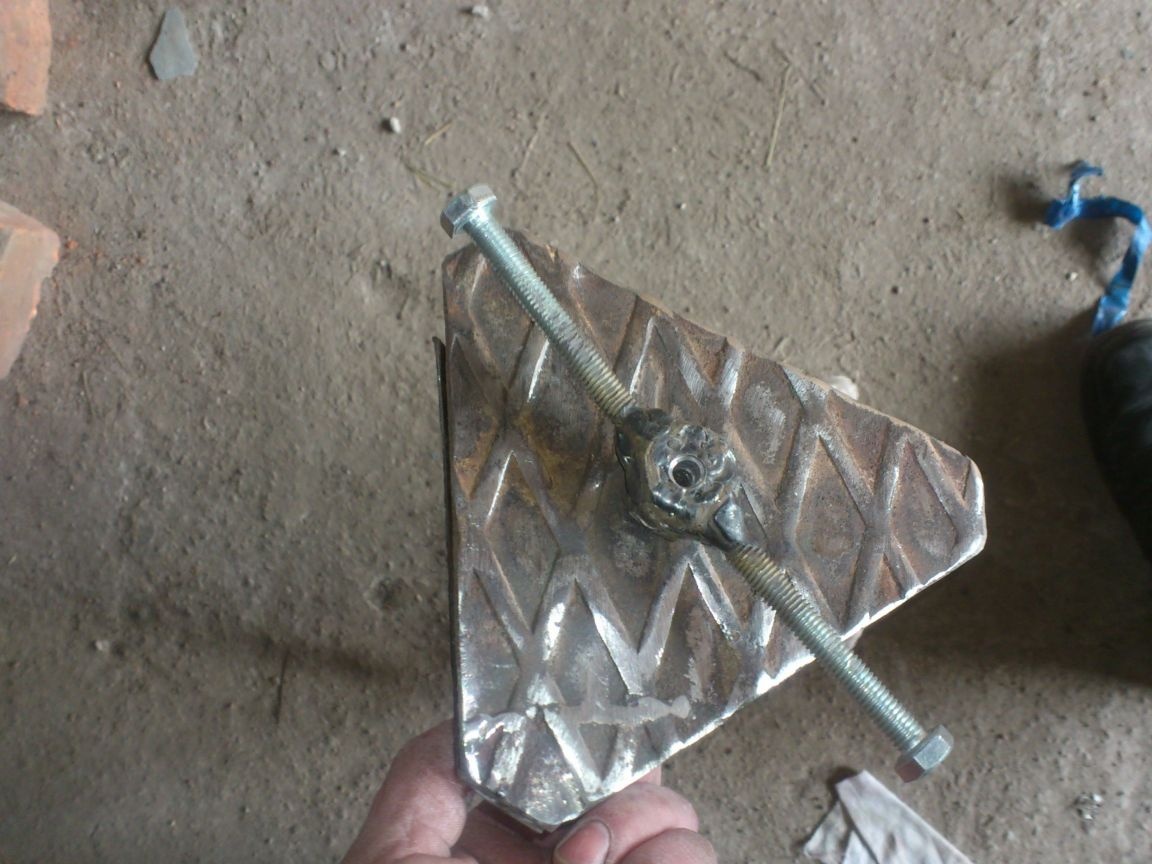
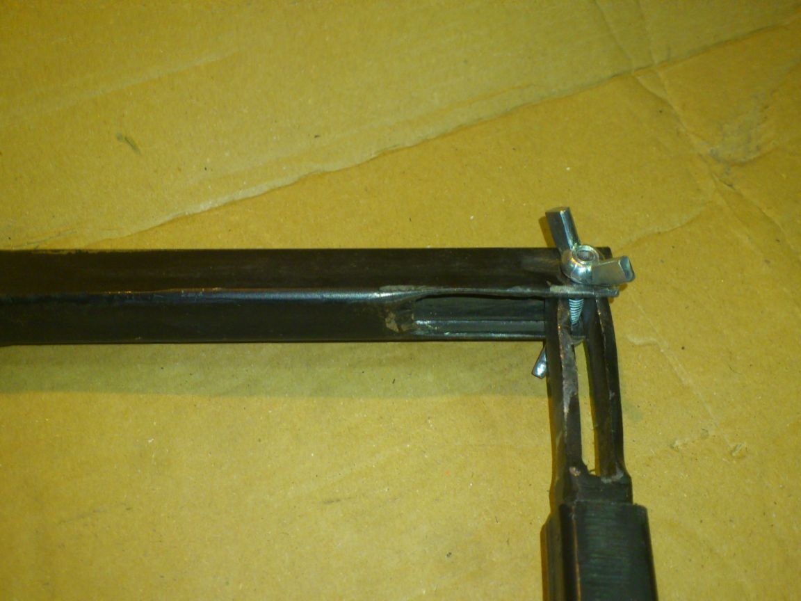
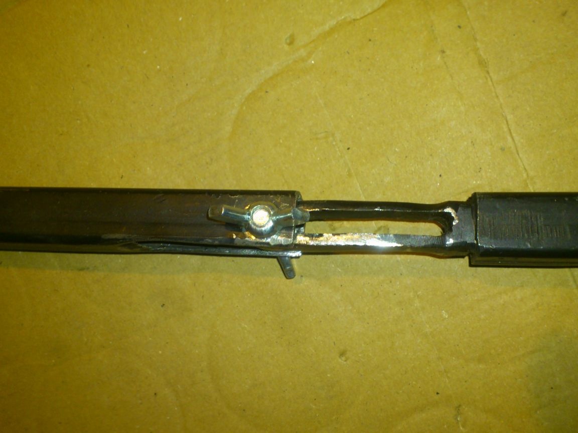
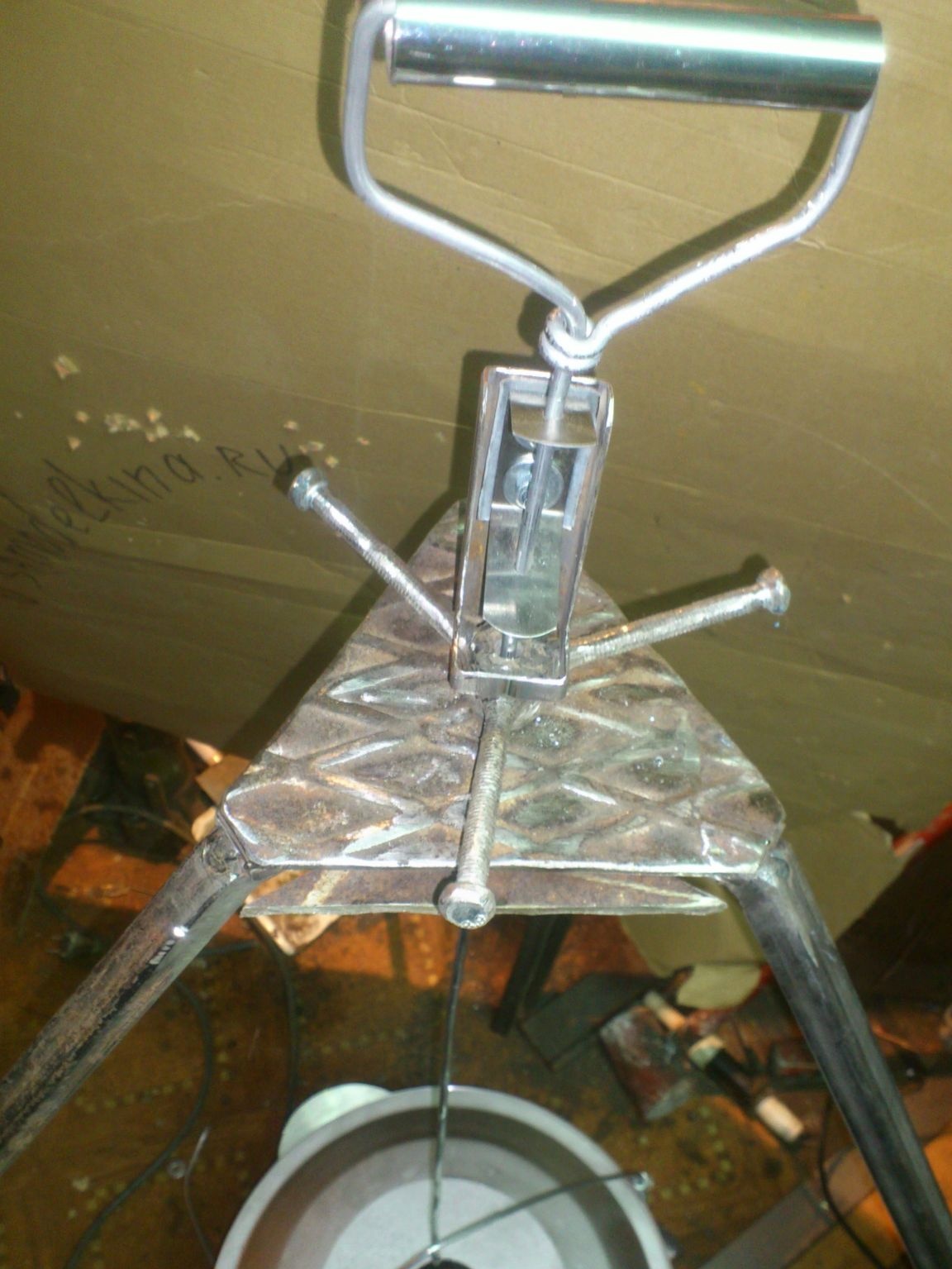
In short ... Here, look at the photo of the finished product, you will immediately understand everything))):
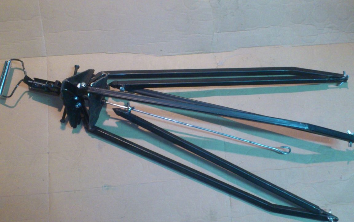
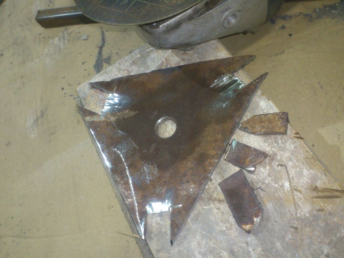
If the stud is loosened and the plates are parted, then the legs can be folded to the position when their long parts become parallel:
That is, the mechanism of folding the main nodes is understandable. Tightening the plate with a hairpin, we make the “legs” diverge until their upper “shoulders” are firmly sandwiched between the plates. The design will take on a hard final shape.
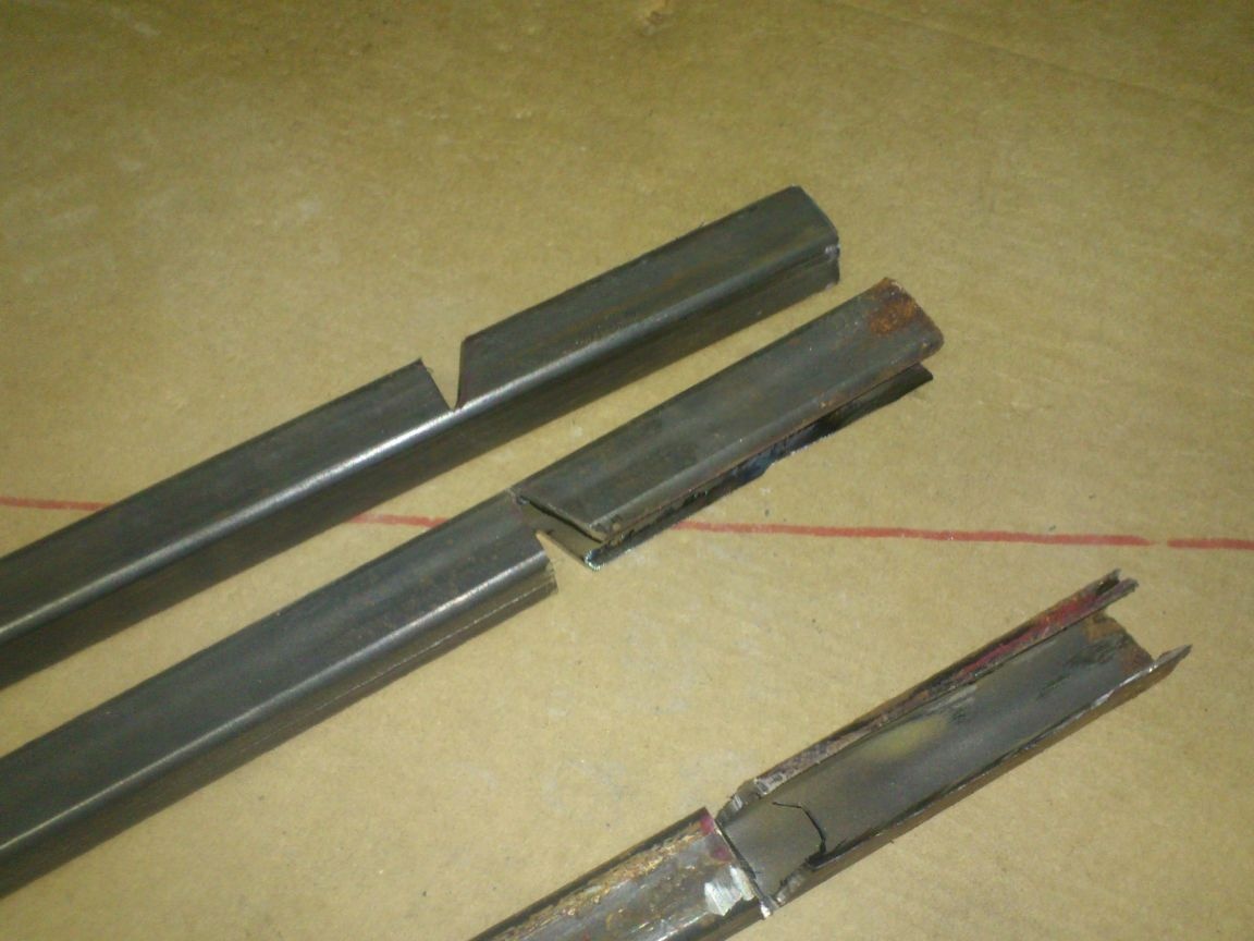
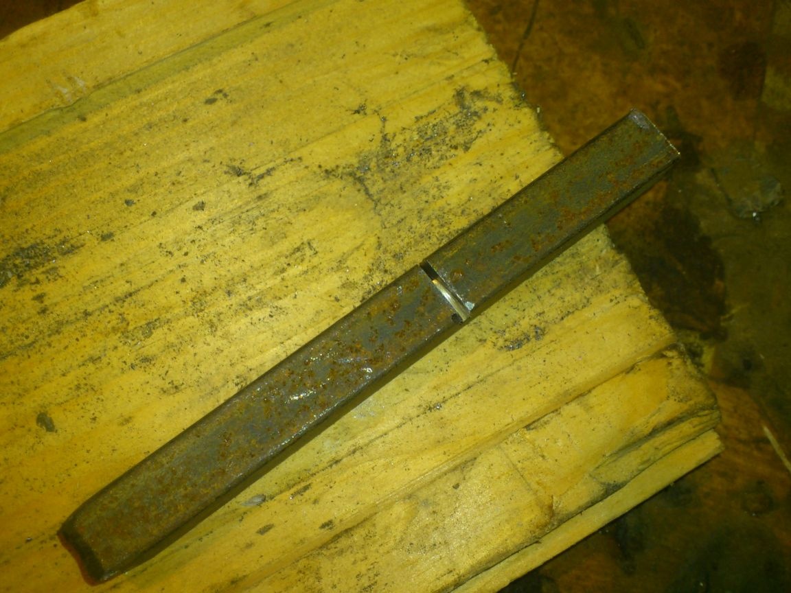
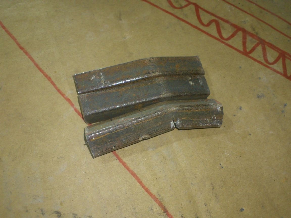
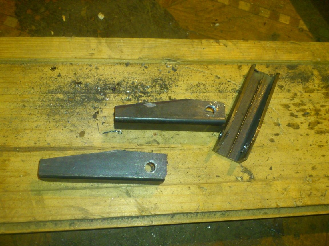
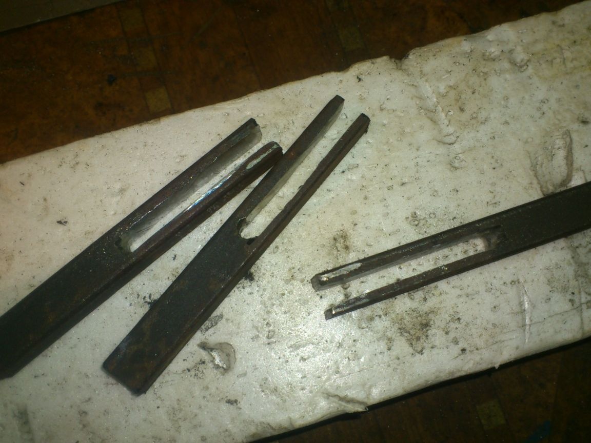
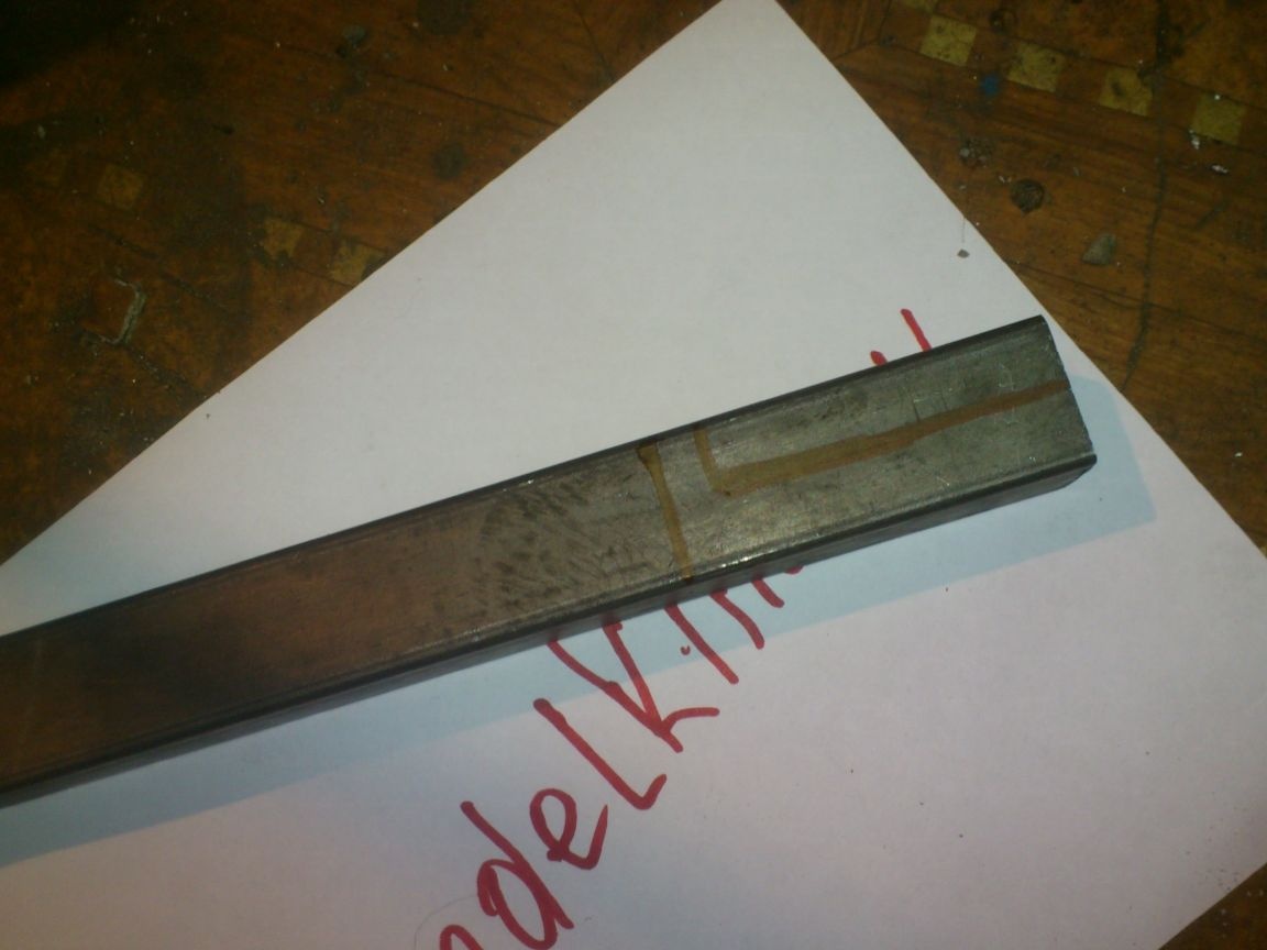
Since it is impossible to bend the profile pipe at the desired angle, I made the cuts according to the template (sketch) of the desired length of the "shoulders" and the desired angle?
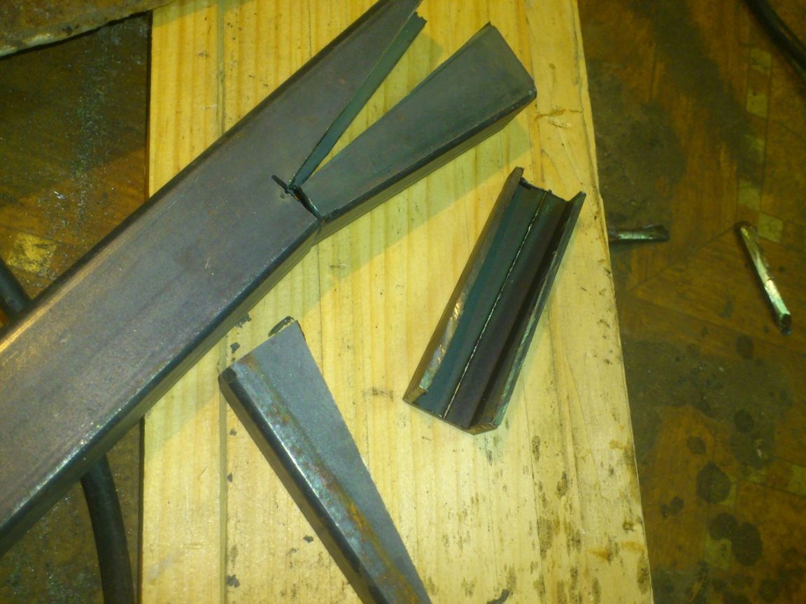
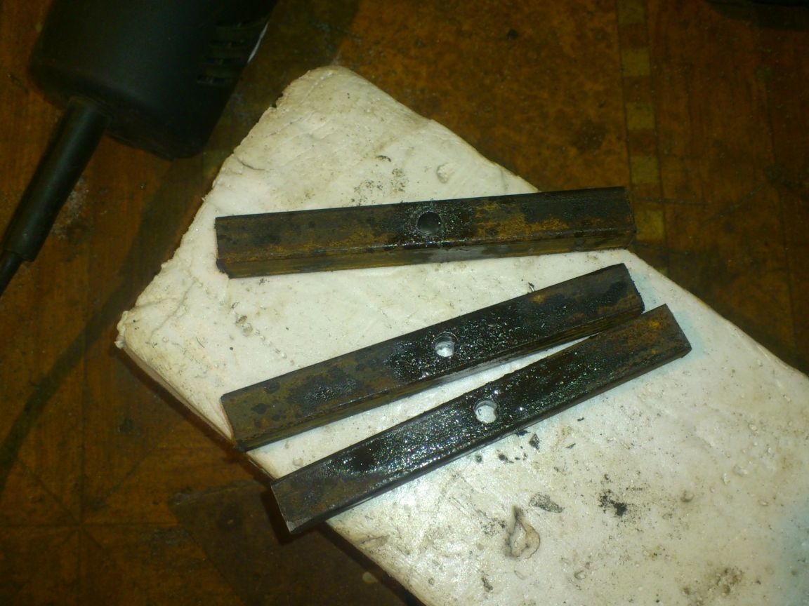
Since the upper "shoulders" will have to withstand heavy loads, I decided to strengthen them. Cut one wall:
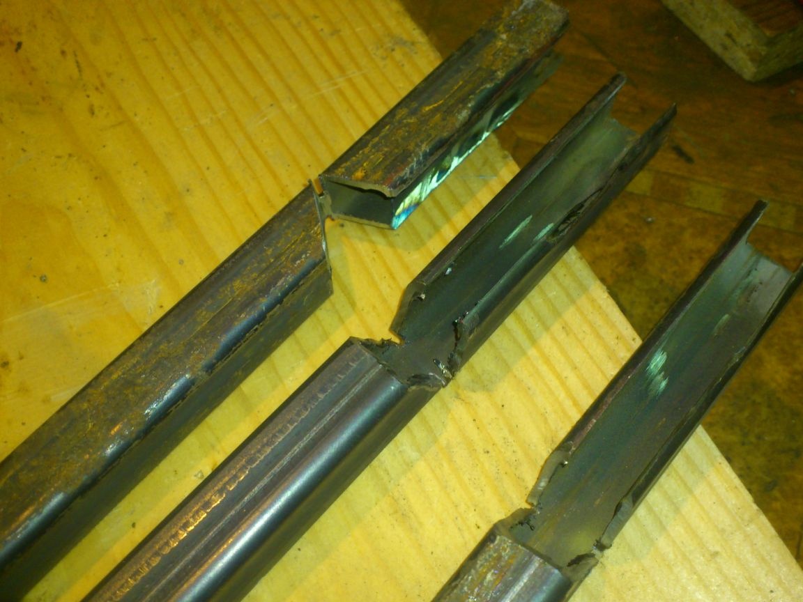
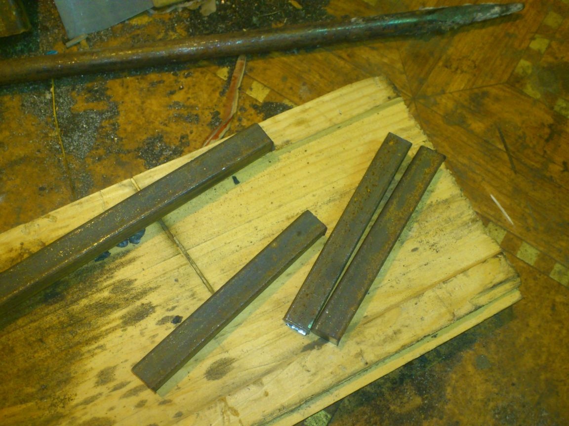
I cut three lengths of 12 by 12 mm square steel and made transverse cuts in them to a depth of about half:
Then, bent to the desired angle using the "hammer-hammer method"

Angle "measured", applying blanks to my sketch.
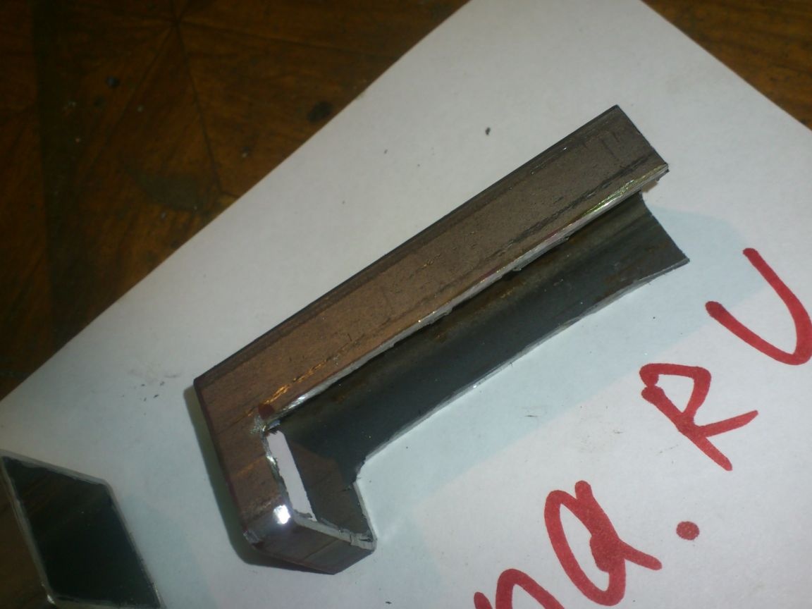
After that, I hammered the resulting amplifiers into the pipe:
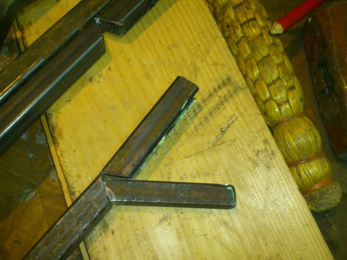
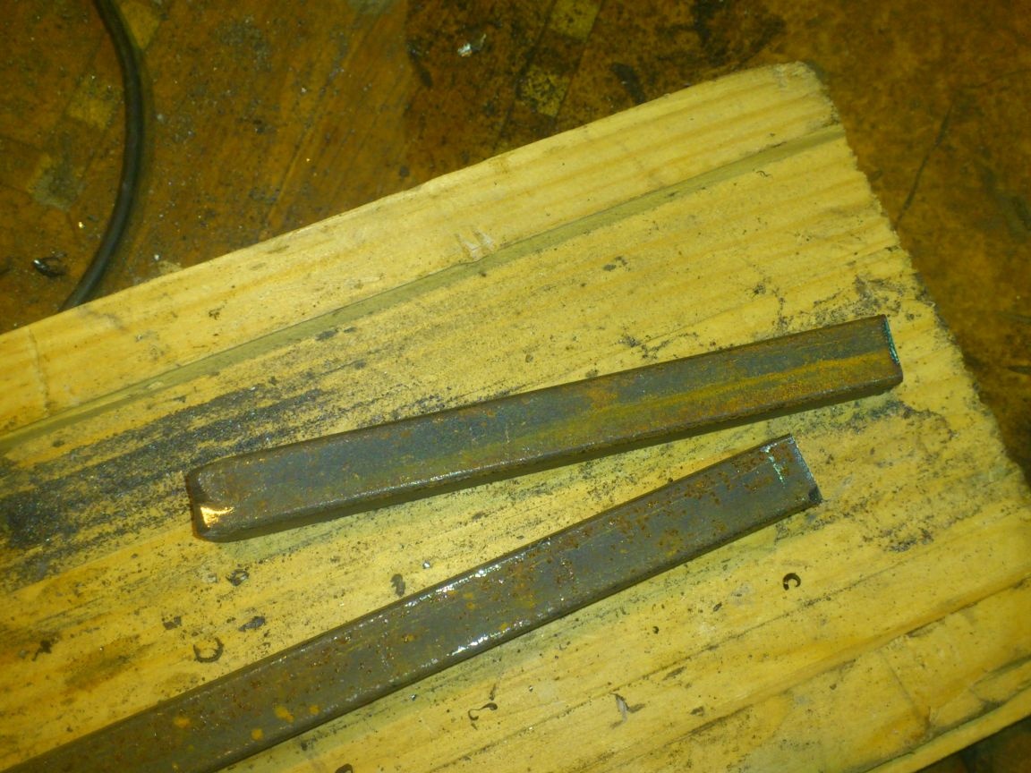
Then he bent the “opened” parts to them and boiled thoroughly, paying attention and an incision at the bend.
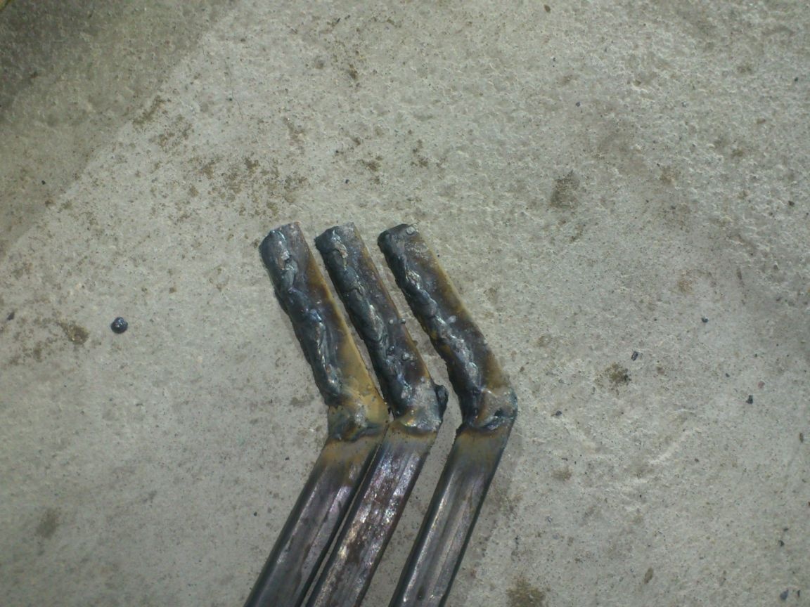
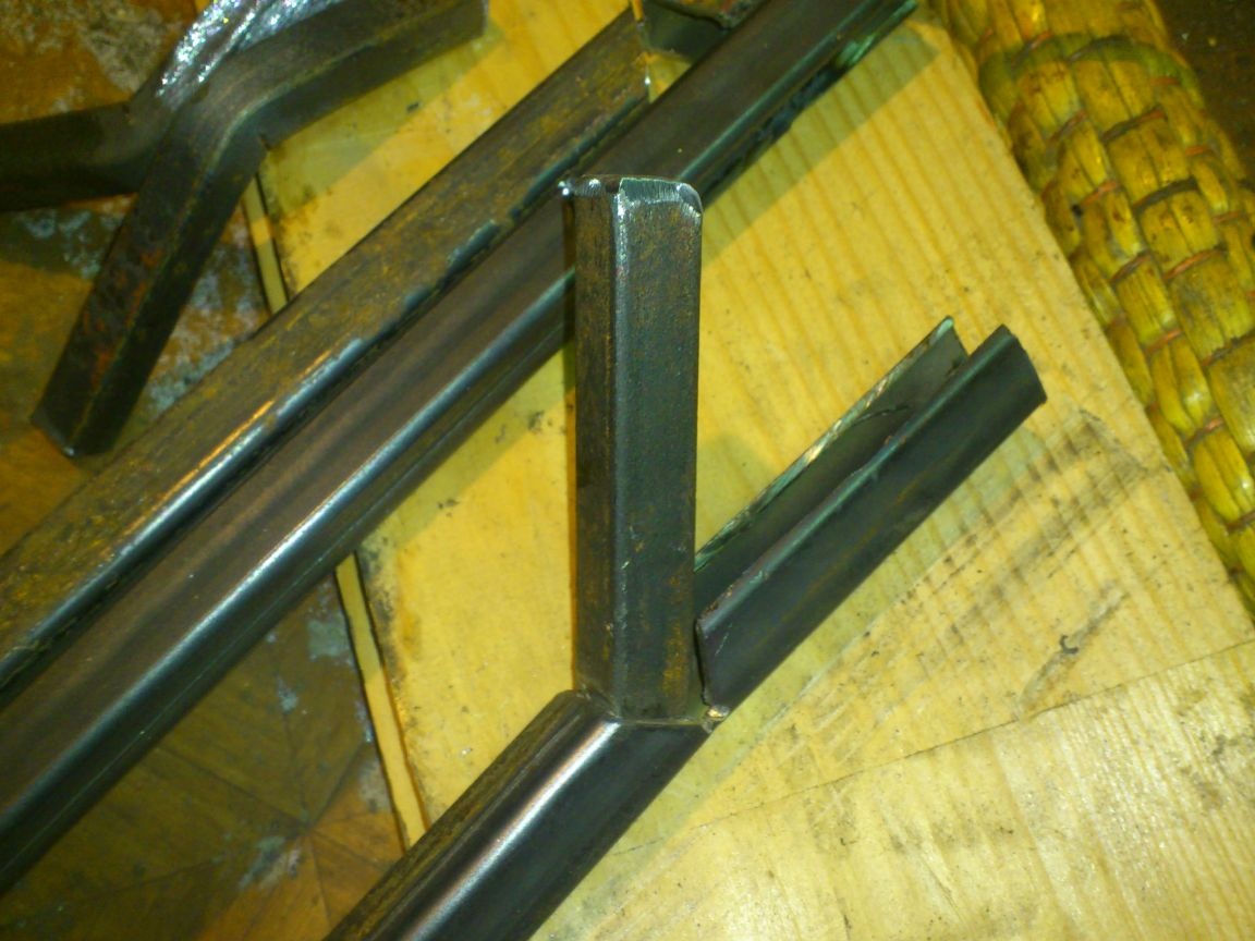
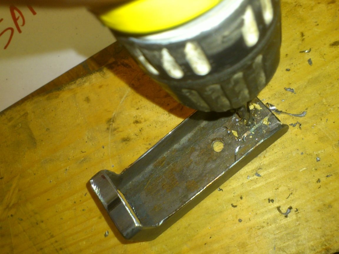
After pre-treatment with a cleanup wheel, he drilled holes under the axis:
Everything ... The upper "shoulder" is ready. I did the bottom with similar amplifiers, I only had to cut off the “shoulders” completely, hammer in the short amplifiers, and then boil it, because the design there will be slightly different:
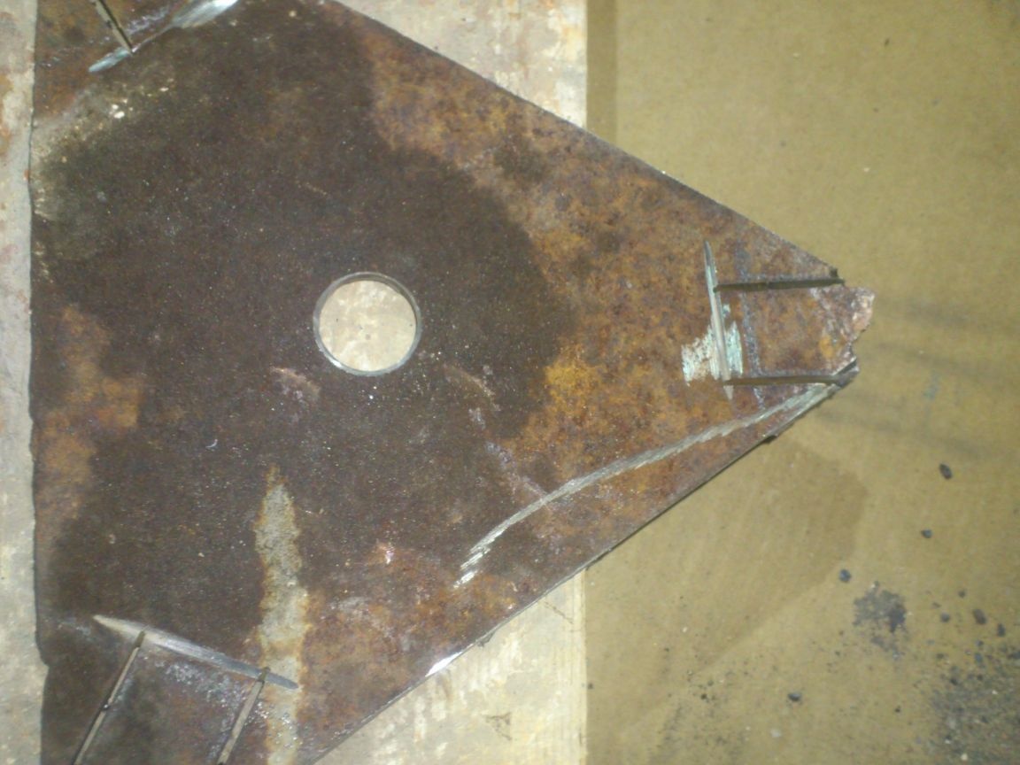
Next, I proceeded to the manufacture of carrier plates. I “deduced” their sizes from the sketch too. I cut them out of an old piece of a five-millimeter "corrugated paper" lying in my scrap metal:
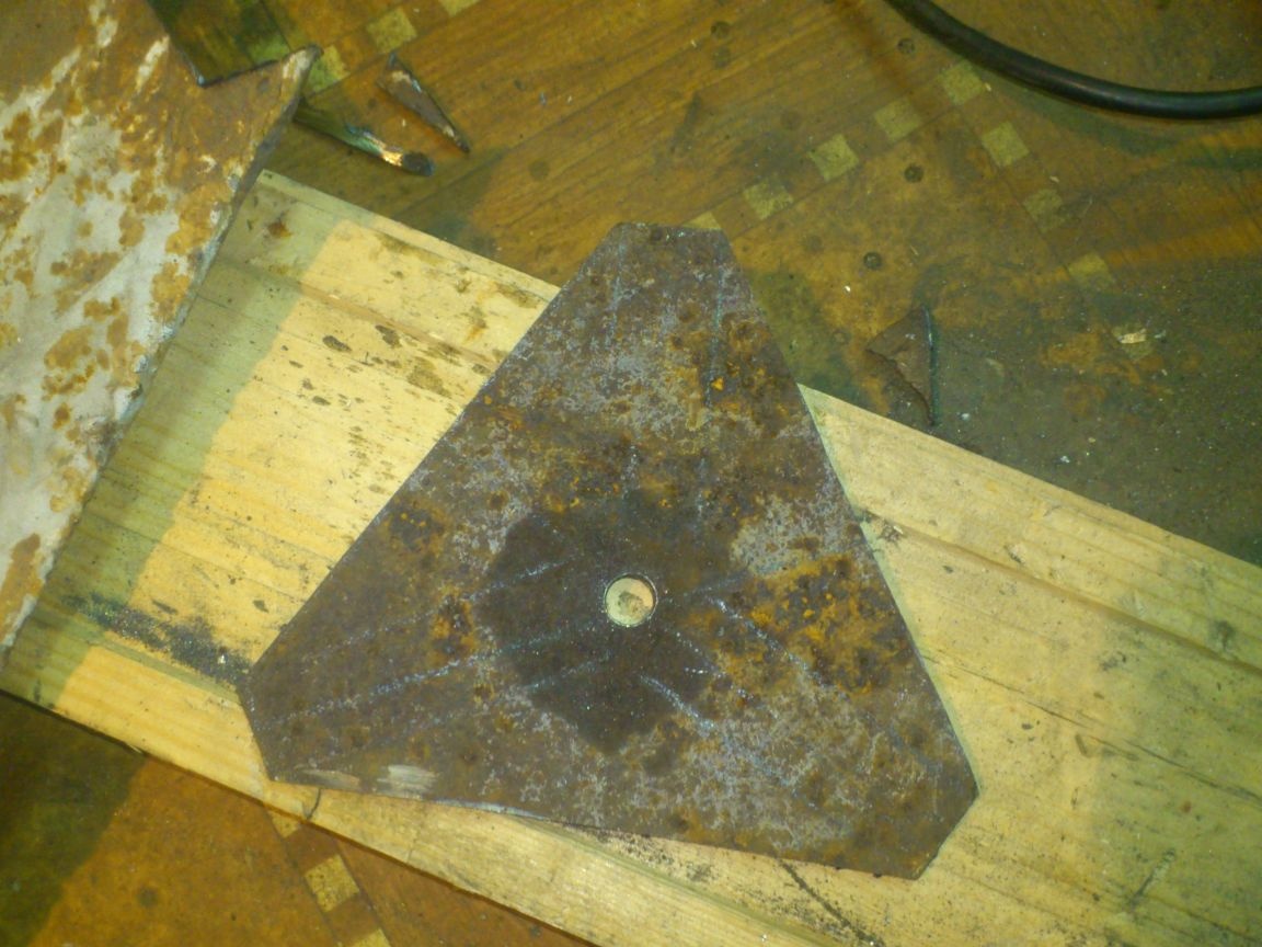
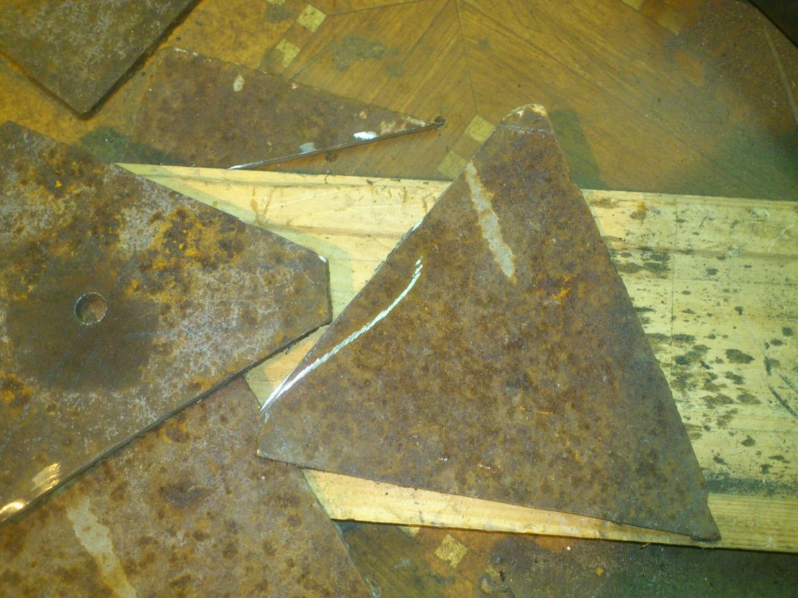
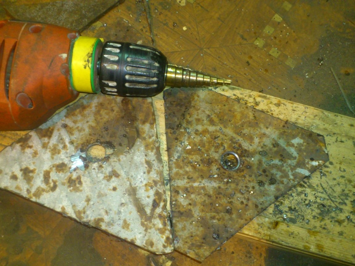
Having found the center, I drilled holes for a hairpin in them:
I cut three “fittings” for the upper “shoulders” from trimming a pipe with a single wall of 20 mm (as I recall, they have a square section with a side of 15 mm, and the inner size of the fittings is 16 mm.):
And welded them to the top platform.
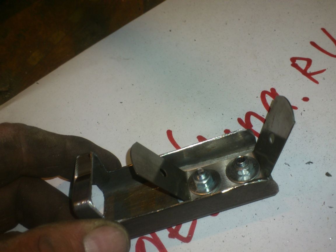
Here I will describe my mistake. Initially, I planned to screw the stud from the bottom, so I welded the M14 nut to the top plate, protecting its thread from splashing the metal with wet paper:
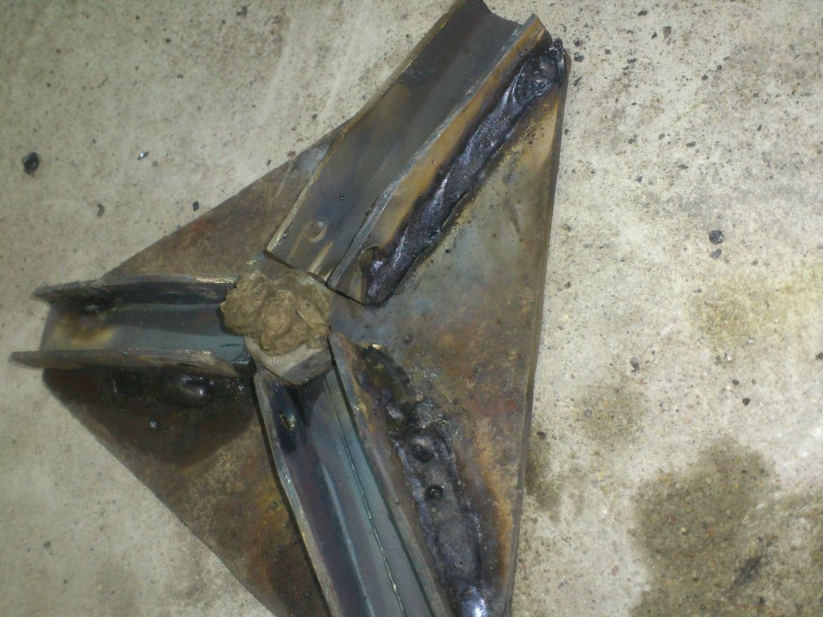
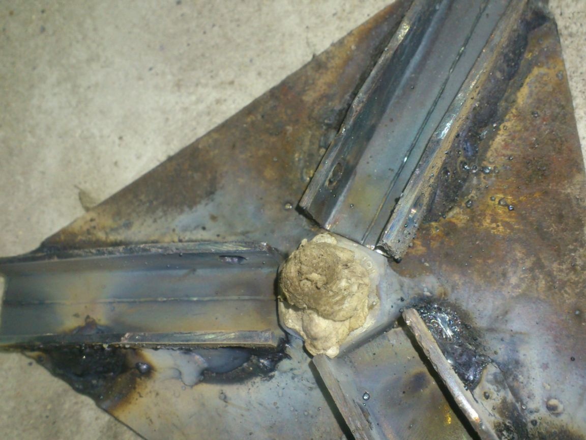
But, already at the first "fitting" it turned out that it was very inconvenient to twist the hairpin from below - the "legs" interfere. Therefore, I drilled a thread in this nut, and welded a similar nut to the bottom plate. Now the pin will be screwed on top.
In the corners of the lower platform, I made cutouts for the “legs”. Now, when we clamp our structure, the lower platform into which the pin is screwed in cannot turn.
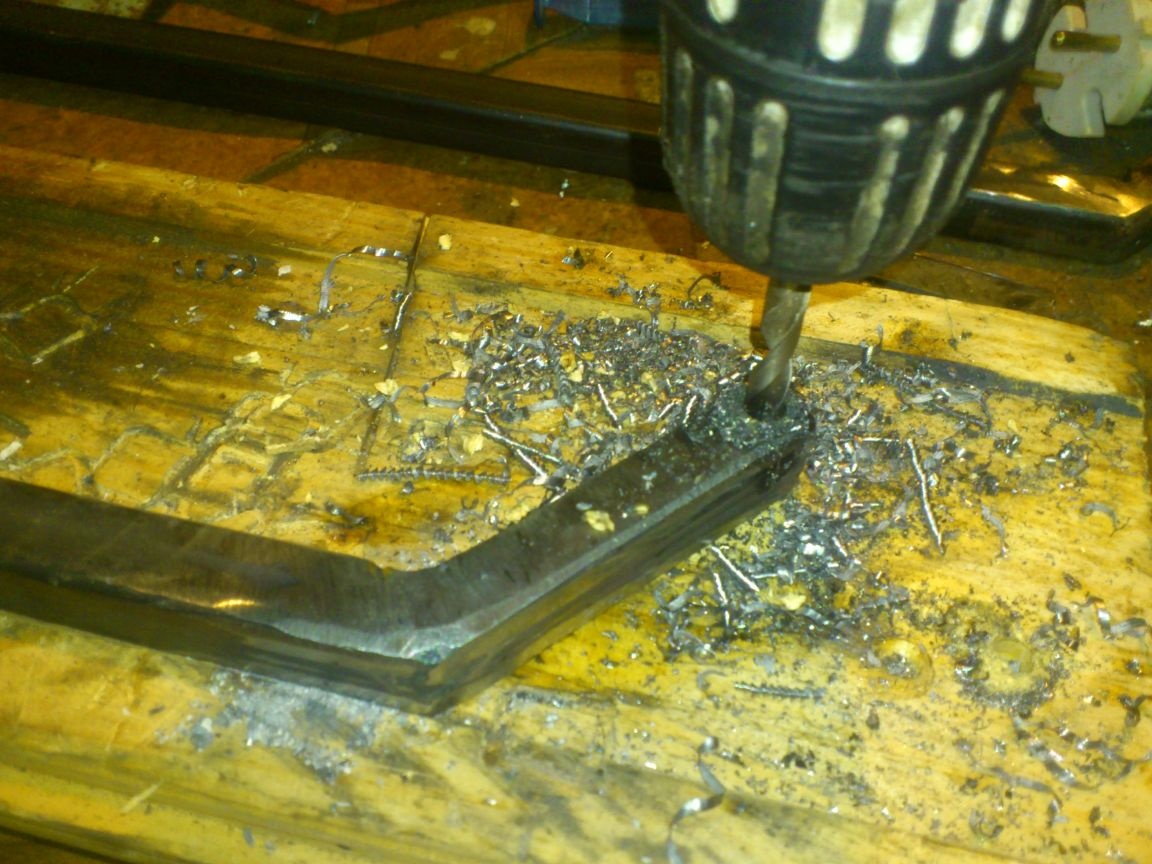
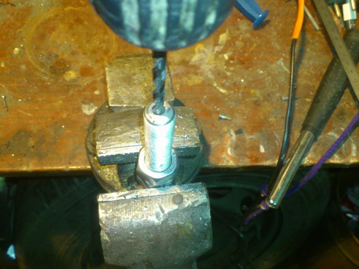
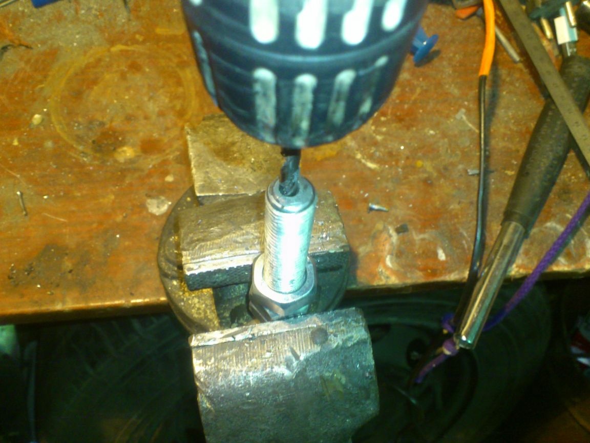
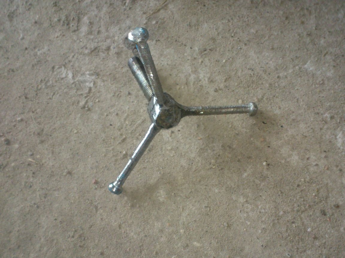
The next thing I started to make a convenient collar from a hairpin. First things first, I drilled an axial hole in it, with a diameter of 6 mm. I will need this in order to make a "tricky" cauldron suspension mechanism, continuously adjustable in height, which I will discuss later ...
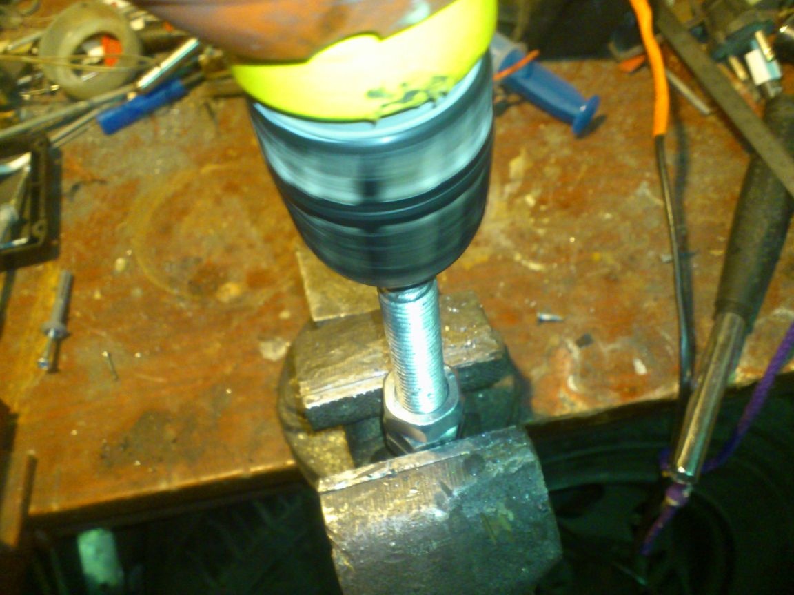
It was difficult to drill a hole. Drilled in a vice. To do this, he screwed three nuts and "locked them" well. He kept it in a vice for them, so as not to spoil the thread:
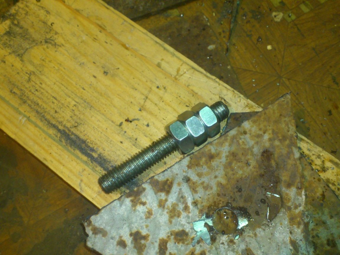
Constantly lubricated the drill, drilled at low speeds, monitored the parallelism of the drill in all planes ... Yes, and the drill is short. Then I had to aim on the other side ....
But it turned out!
To make the winch, I screwed two nuts on the end of the stud and welded them:
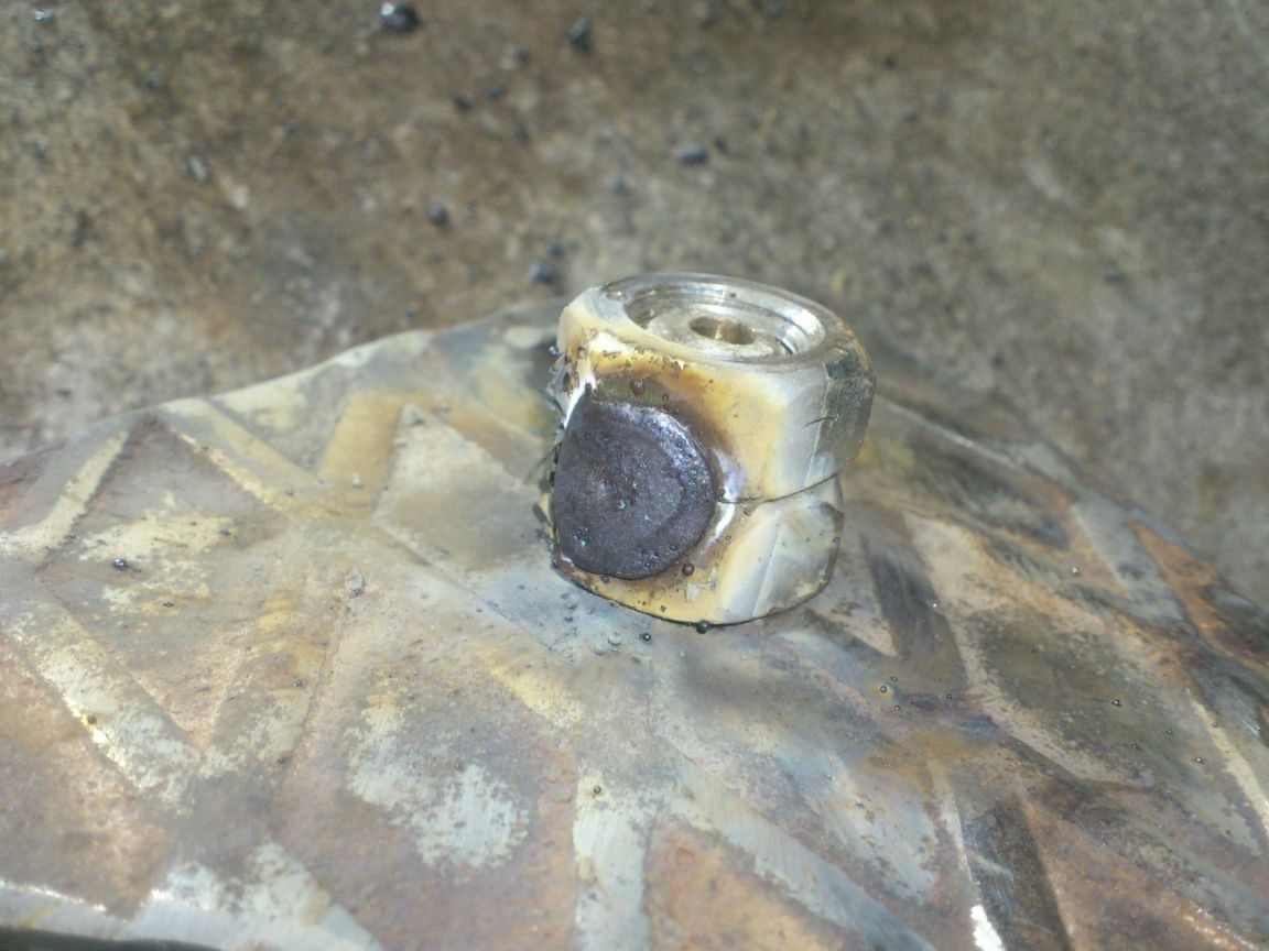
Then he drilled two blind holes in their faces (so that they reached the studs), hammered bolts into them and welded:
.... And I realized that I was mistaken again !!!
Since my tripod folded in cross section will have a triangular shape, it will be logical to make the case for it triangular! And such a collar in any case will protrude beyond the limits of the tripod ...
So I cut one bolt:
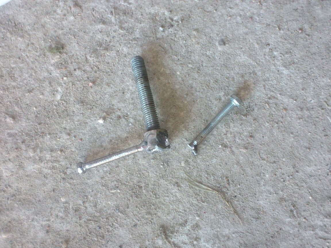
And welded two:
Such a collar can be rotated so that it will not stick out beyond the upper triangular plate, and it will be even more convenient to rotate it than a bolt with two shutters.
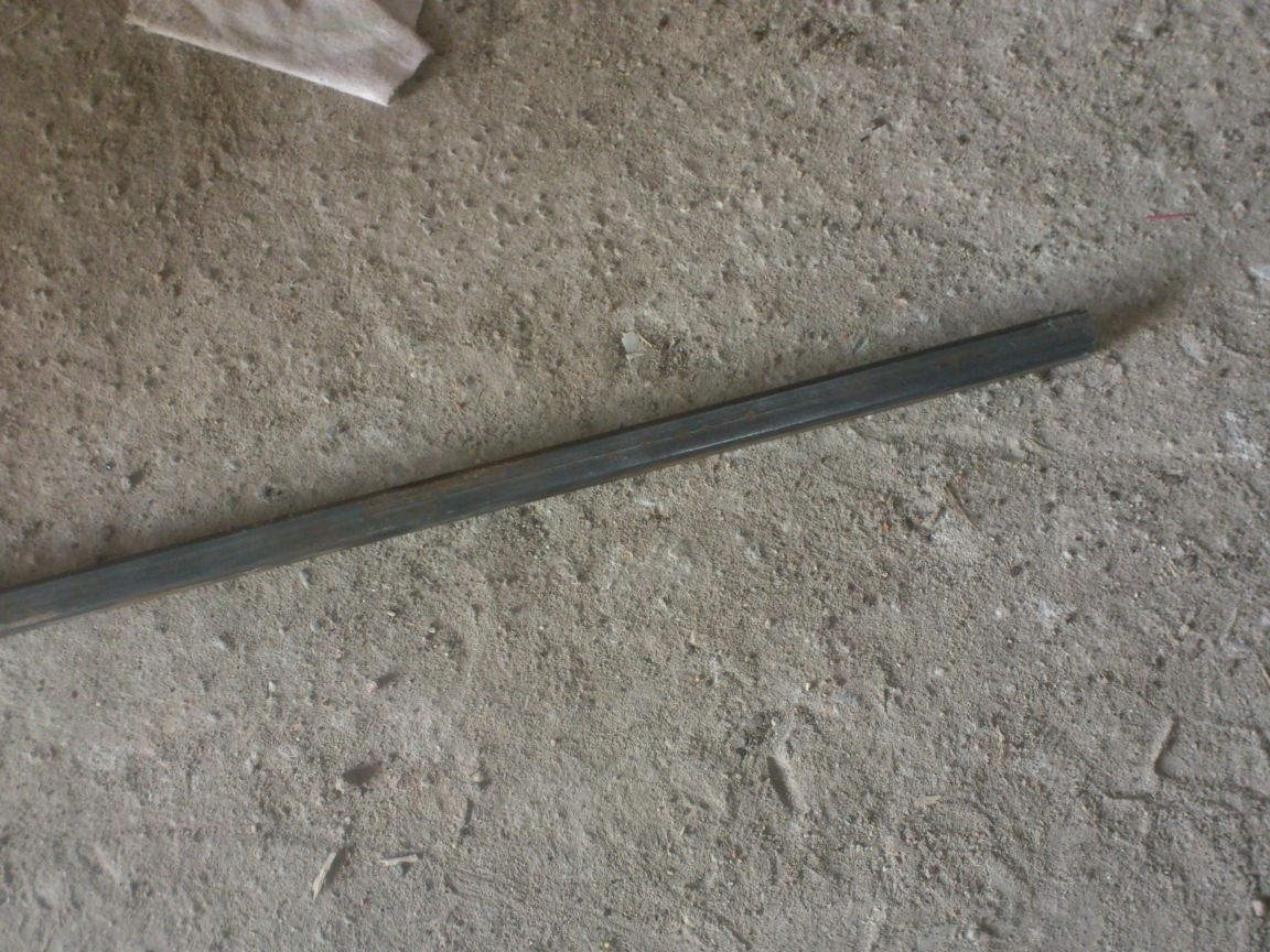
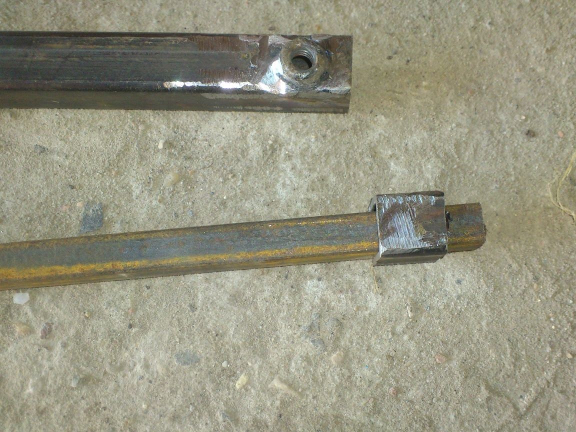
Next, I began to manufacture the lower parts of the “legs”. As planned, they will be telescopic. From a 15 by 15 pipe, a 10 by 10 square will come out.
(A profile pipe has a wall thickness of 1.5 mm. Theoretically, a 12 by 12 square bar should be included, from which I made amplifiers. But in practice, it is only clogged with a sledgehammer, since the pipe is welded and has a weld seam inside. Therefore, I chose a smaller section).
Telescopic extensions will be clamped at the desired position by wing bolts. Therefore, having cut out three pieces of the pipe of the required length, I drilled holes 8 mm in diameter closer to the edge of them and welded them over the M6 nut:
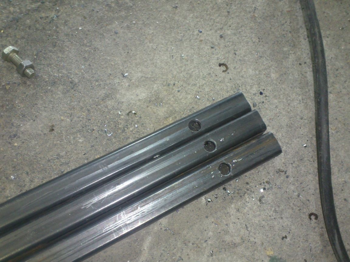
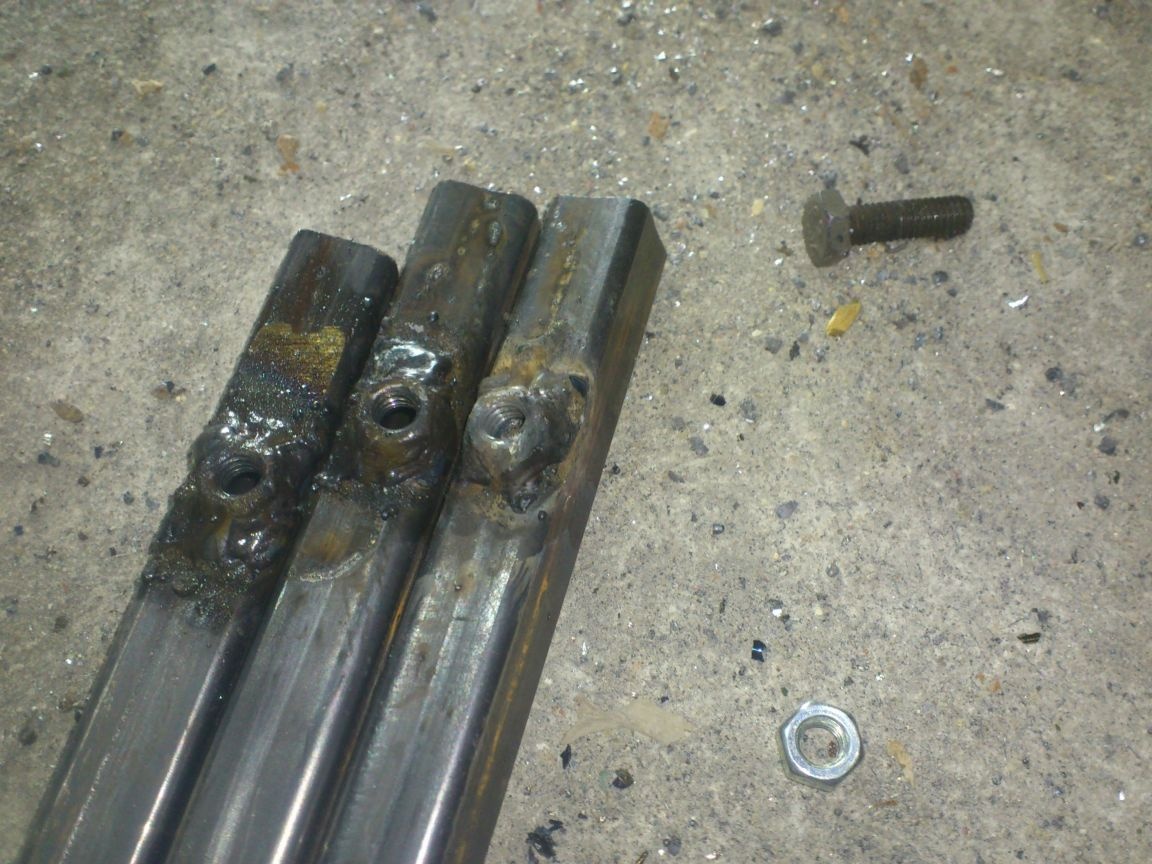
It was hard enough to do by arc welding. To fix in the right position and to protect the thread from splashing metal, I used a bolt, which "do not mind"))))
Next, I cut out three segments of the square of the desired length (inserted in and cut off the protruding part).
From all the pipes behind the welded nut I cut off the "excess":
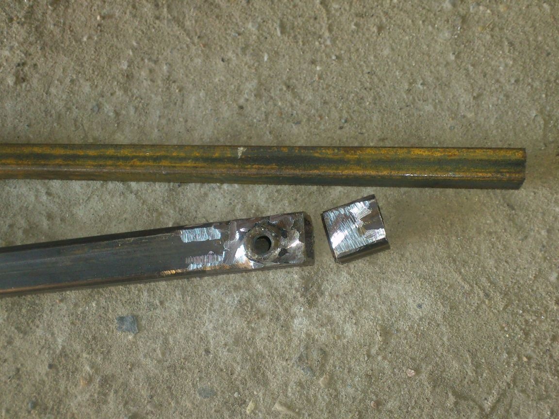
Put it on the rods:
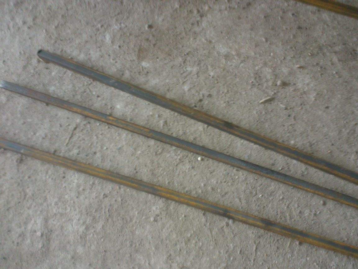
Welded and sharpened:
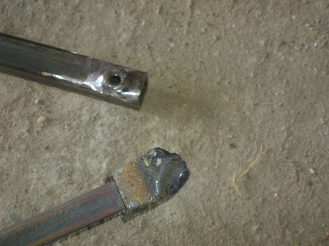
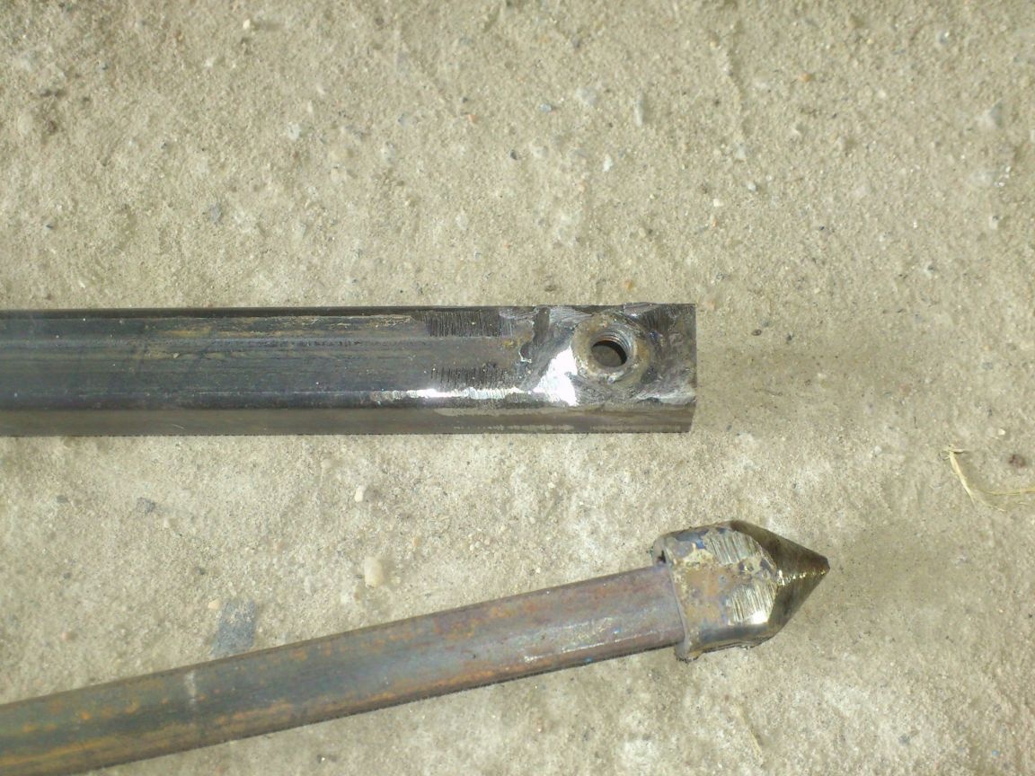
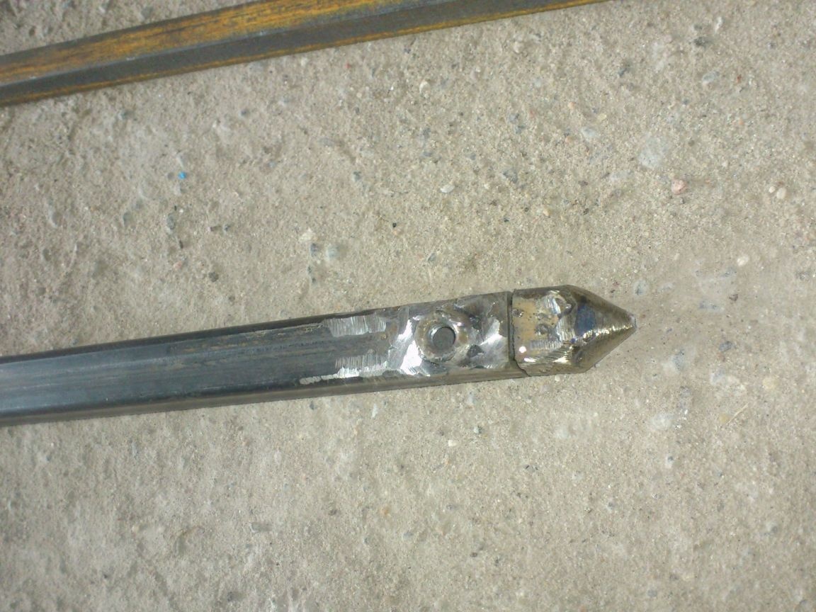
This design will protect the inside of the pipe from clogging with the earth if we stick it into the ground without unfolding the telescopic part, and at the same time serve as limiters - it will not allow the rods to go inside when folding more than necessary .... Yes, and it looks somehow "more organically.")))))
... Initially, I thought about how to limit the departure of these elements. And, even, he came up with ... but he abandoned this venture because then the telescopic structure would not be collapsible! And if sand is poured inside, it will be problematic to clean! Therefore, I decided to exclude this moment, and in order not to accidentally stick out the “legs” more than I should, simply paint their upper part with red enamel. As soon as red appeared - stop! You can’t put forward further!
Now we will do the top mount. According to the idea, it should develop. But you won’t make it telescopic - the “knee” on the upper part interferes. And if you just fold to the side on the axis, then there is not enough rigidity. Therefore, I came up with such a compromise solution:
The “legs” will be folded on the axis, but, having spread them 180 degrees, you can feed a little back so that their ends enter the tube of the upper part, and clamp in this position with a wing bolt with a wing nut. You will get a rigid mount at two points - the hinge "immobilizes with a telescopic moment!"
I embodied this as follows:
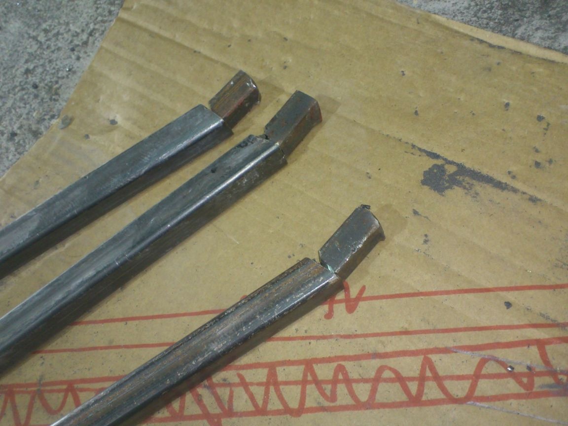
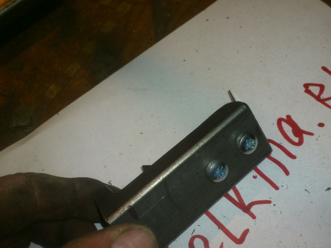
I cut three segments of a square with a side of 12 mm and drilled holes in them with a diameter of 6 mm:
After which, the grinder cut one side along:
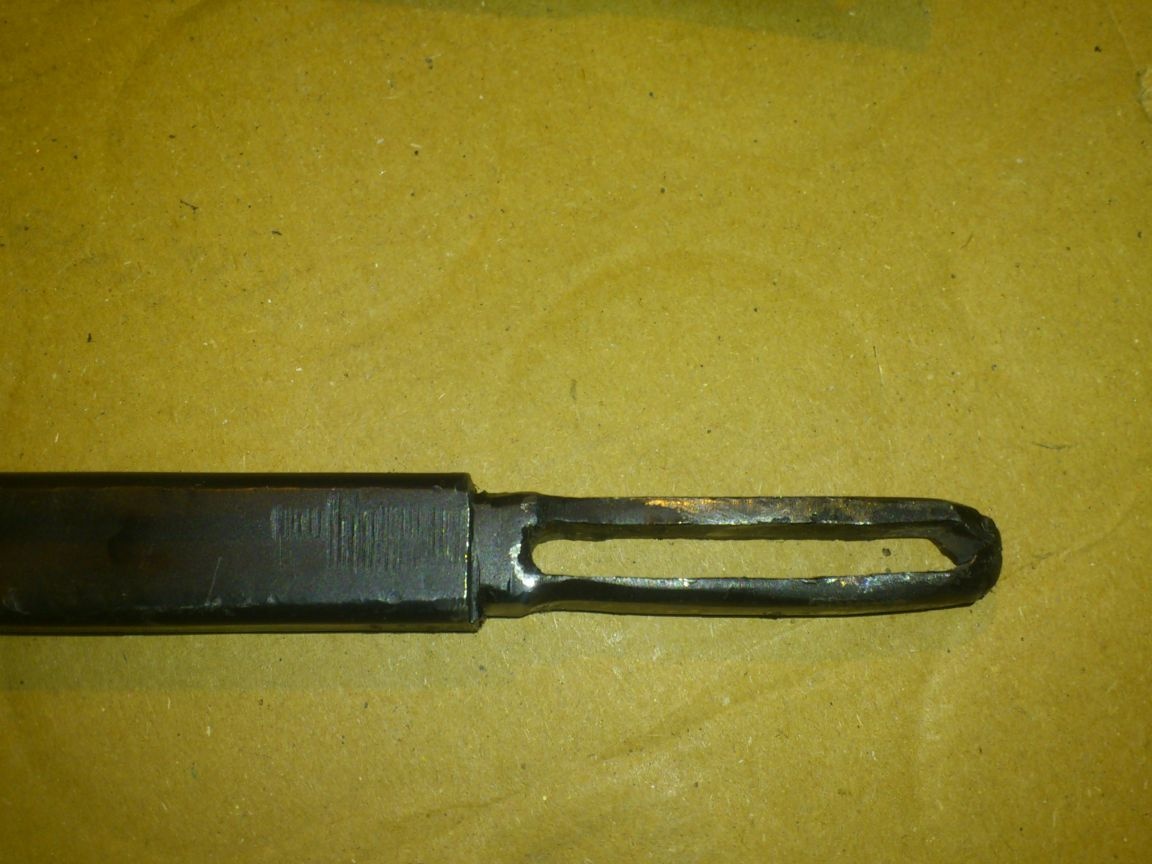
To "drown out" the ends, I clamped them in a vice, putting a bolt into the slot, and simply bent the walls to each other with a hammer. After that, he “pecan” a little by welding and turned it in a cleanup circle to give the desired round shape. (Unfortunately, I forgot to take a photo of this process, so I post a photo of the finished element.
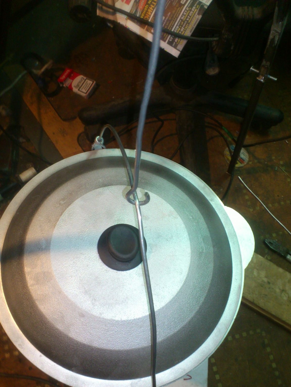
Now we are going to manufacture the suspension mechanism. I have already described my requirements for it - the main thing is that it will have to provide smooth height adjustment without removing the boiler (cauldron) from the hook. I decided to carry out this function using a suspended spring element from the Armstrong ceiling system.
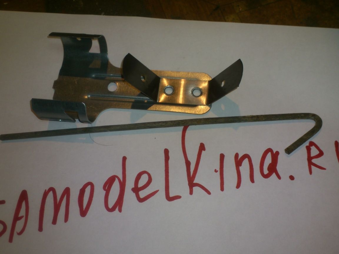
Those who are not familiar with this system, I will explain. The main element is two petals of their spring steel arranged in opposite directions, in which there are holes. When compressing them with your fingers to a parallel position, a wire hook of 4 mm thick wire is inserted and easily moved through the hole. And if you let go, the petals tend to disperse in different directions and securely fix the hook in the right position:
I decided to use this element. Manufacturers guarantee that it can withstand a long-term load of 25 kg. But this is reinsurance! For the sake of interest, I myself hung on it)))). He also sustained my 90 kg!))) And, only when I started to jerk specifically, the hook began to creep out a little from its position, and then the spring came off the base - the tubular rivets with which it was fastened could not stand it.
That is, to withstand the required maximum 25 kg, the strength in it is enough with a huge excess!)))
..From the suspension, I cut off with the grinder only the part I needed - the spring itself. As I already said, it is fixed with tubular rivets, so I decided that it would be easier to just pass the fixing screws through them than to drill the rivets and fix the spring again:
From a piece of profile pipe 40 by 25 mm, I made this detail:
And fixed the spring to it with two M5 screws and nuts:
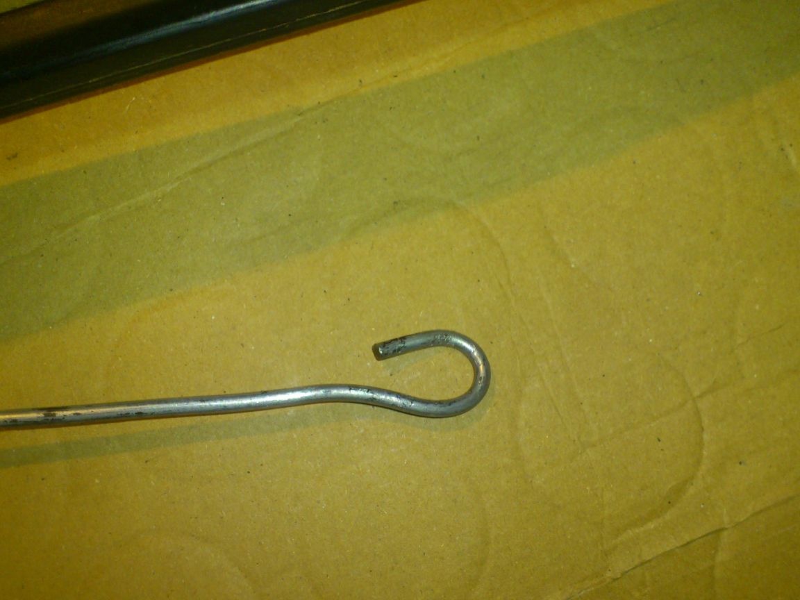
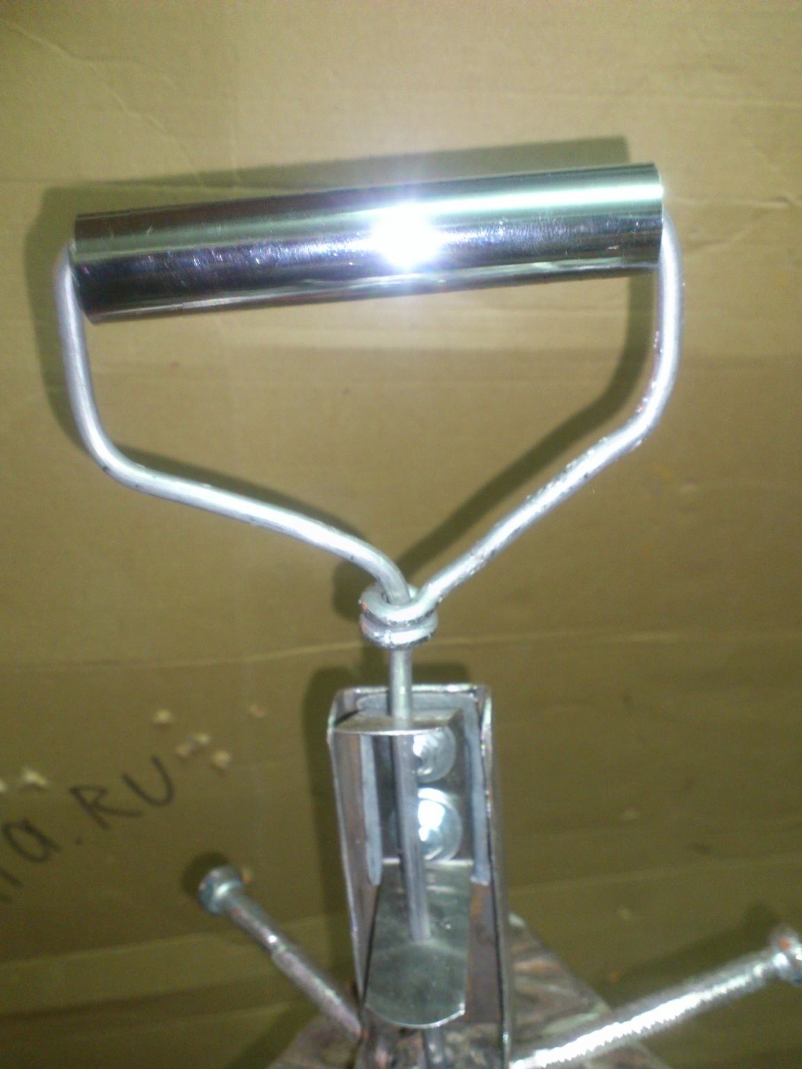
I made the suspension myself from a wire with a diameter of 4 mm. Passing it through the hole in the tripod clamping pin (that’s why I drilled it!))), I bent the lower part in the shape of a hook
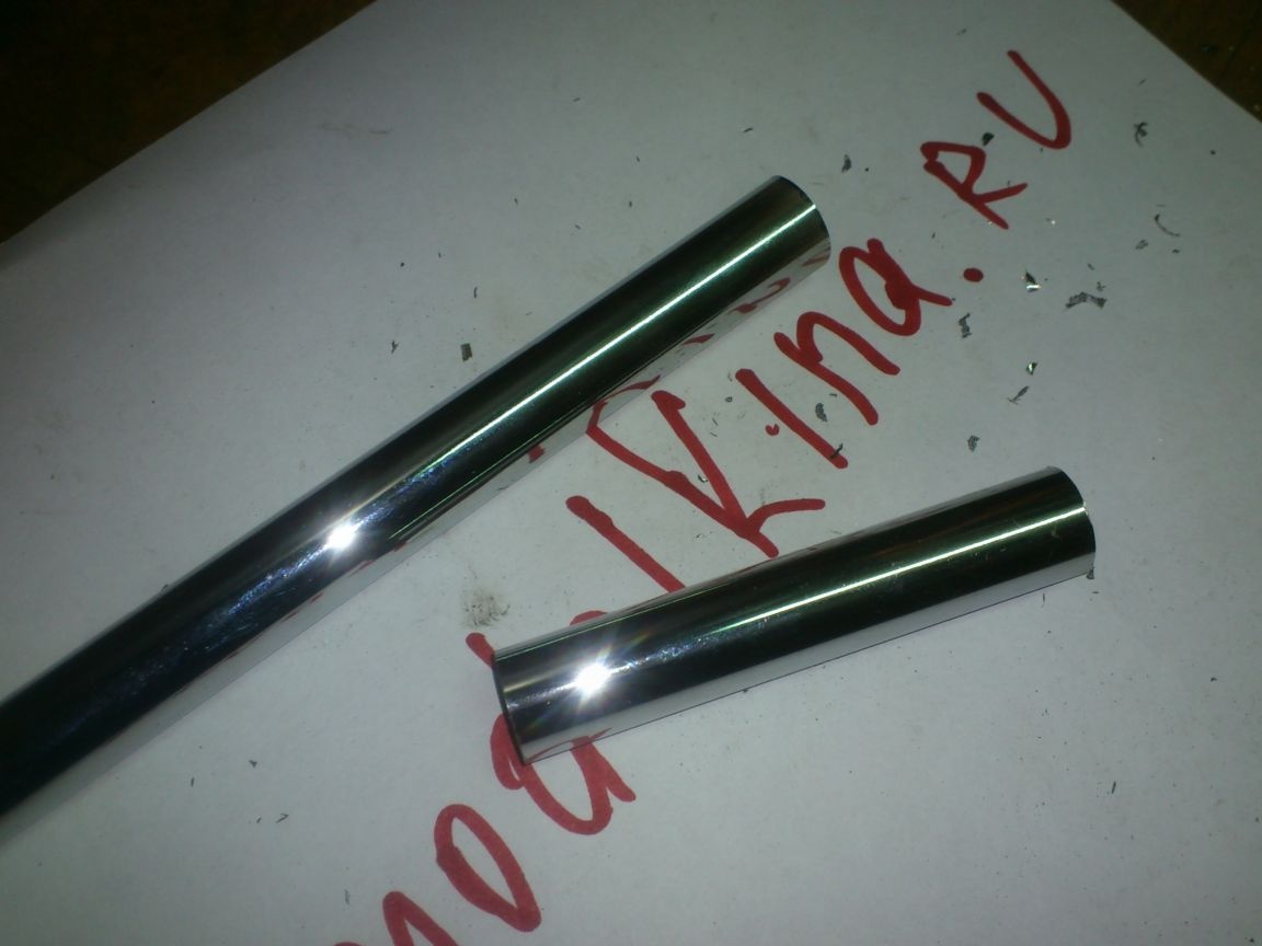
... and on top put on a spring clip and also bent, giving the shape of a handle. For convenience, I put on a piece of chrome-plated riving tube:
Well, actually, that's it! After the preliminary assembly, I again disassembled and painted the tripod with heat-resistant enamel: