

I will continue the description of my Internet searches in the village.
After log-periodic, several versions of the Harchenko antenna were manufactured. The antenna is simple in design and quite effective. It is very popular among lovers of television reception, it is often used for data transfer, including as an external antenna of a GSM modem. Perhaps you should not dwell on the theory and calculations, there are a great many of them in the network, of varying degrees of depth. Here I brag about my performances with comments.
If you want to repeat any of the designs, we need a minimum set of locksmith tools, a powerful soldering iron, accessories and soldering materials. Jigsaw on wood. Tolika patience and accuracy.
So.
We can say a prototype, a reflector made of foil fiberglass. Studs on the edges of the frame from the same wire - in these places there is zero potential and it is allowed to use metal fasteners, which is convenient. In theory, it is worth striving for good symmetry of the frame and correctness (compliance with the design form), which is not so easy to achieve with thick wire. A simple snap comes to mind, at least in the form of a wooden “cube”, which can be placed inside the frame with a wooden or rubber mallet, without fanaticism, to align the corners and shape of the shoulders.
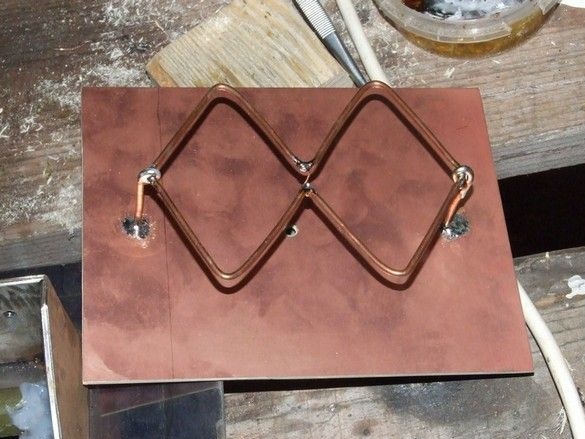
The above-mentioned equipment was not used - it was decided to act more radically by making a frame from a rigid sheet conductor by sawing. The mentioned foil fiberglass was applied.
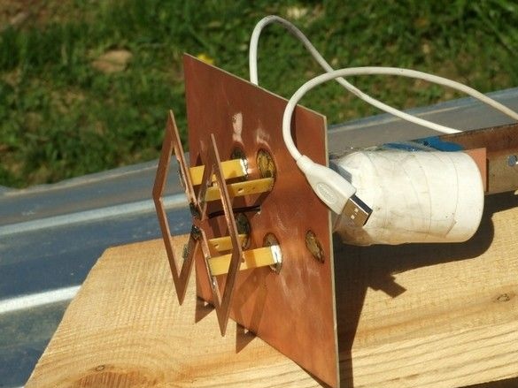
In the photo, behind the reflector, in a jar of vitamins - a modem, a USB cable 35 ... 40 cm long was soldered to it to death to avoid unnecessary detachable connection "on top" and reduce the length of the modem. The reflector is a foil-coated stelotextolite; in fact, it is soldered from the previous design. The antenna was guided by the guidance unit from past experiments with log-periodic a colleague. The old "infrastructure" was also used - cables, power supply, mounts.
The frame was drawn in AutoCAD and printed in full size. The drawing in the right place of the workpiece is fixed with tape and slightly piled in the corners. It remains to draw the sides of the frame with a sharp awl, connecting the core points and you can cut it out.He sawed it with a manual "pioneer" jigsaw on wood. Native files for wood.
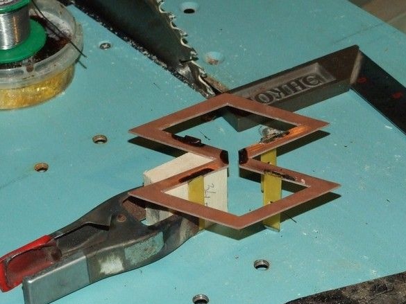
Attention deserves a way to attach the frame to the reflector. It was decided to fix the frame at four points. The racks are made of the same foil fiberglass. Foil in addition to two-millimeter strips along the edges is etched in ferric chloride. Installation by soldering, 60 W soldered well. For convenience, a snap was made - a wooden cube with finely sawn ends. The process in the photo. All copper, well soldered with vulgar rosin.
It is worth saying that laminated plastics, including our fiberglass, are very porous in origin, pores are many and small, respectively, hygroscopic material. A good tone will be a pair of varnish layers, otherwise the parameters may float.
The last design smoothly flowed into the irradiator option for the reflector from the satellite dish.
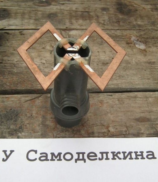
The same frame of foil material is fixed in a node assembled from plumbing. It seems to have been a drain (water lock) for a conch. Its diameter went well to the standard mount satellite dish converter. The frame is fixed with hot glue in the cuts of the plastic pipe. The decision is controversial and probably not too long-lasting - at sub-zero temperatures such glue becomes quite fragile.
On the reverse side, a modem was conveniently placed, fixed by two Penoplex plates.
A piece of plastic from a plastic jar, from precipitation, is densely jammed from above.
The entire assembly, with mounting from a plate. Outgoing hose and rubber cuff from draining the washing machine. The cuff seals the elbow with the corrugated hose.
Inside, the standard USB plug fits neatly, it was very convenient.
The most interesting is the twin version.
Made twin sister of the previous frame with racks. The reflector was selected more thoroughly, from a 1.5mm stainless steel plate. Steel, including stainless steel, is well soldered by ordinary tin-lead solders with “soldering acid” (zinc chloride) or phosphoric acid as a flux. Do not forget to solder the place thoroughly before, and rinse thoroughly (with water) after.
To power both frames, it was decided to use part of the piece of iron from some kind of military antenna.
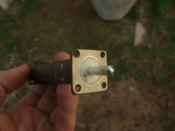

The piece of iron, in fact, performed similar functions - powering four vibrators in the form of aluminum gratings. The whole structure took shape, which suggests its automotive, hmm, basing. From the bars, a neighbor made a collar, and gave me too much :)
Execution inspires respect - everything is neat, powerful, silvering is everywhere inside. The fragment in the last photo is supposedly a choke that prevents stray currents from flowing onto the cable braid.
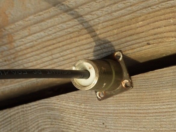
Functionally the same choke, but for our antenna, was made of a piece of the old. A coaxial cable was coaxially passed through the cylinder, with a flange of the required size, and fixed with epoxy glue.
Ready-made splitter assembly.
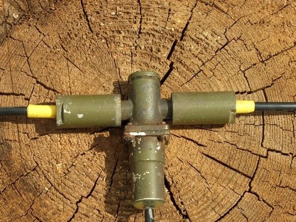
Didn’t it turn out a photo with a hint of some artistry?
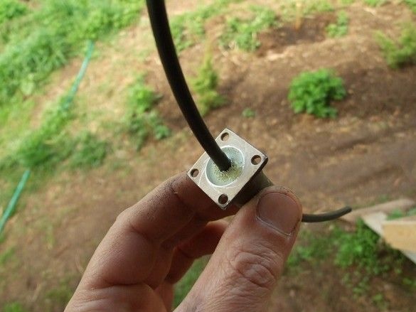
On the reverse side of the “tee” there are M4 threaded holes for convenient and reliable mounting on a flat surface.
The inner connection of the central cores of the three cables is made through this technological hole, then screwed into a stopper, silver plated of course. The connection of the screens is structural.
The reverse side of the antenna with paired frames, the splitter is mounted on the reflector, the ends of the cables are cut and connected, probable leaks due to cracking of the native rubber gaskets and the use of an abnormal cable of a different diameter are additionally sealed with a neutral silicone sealant. The bracket for attaching the antenna in the guidance unit is bent from stainless steel and welded to the reflector.In the long shelf, two holes are drilled, matching the same ones, in the rotary assembly. The antenna is mounted with two short M6 screws. Under the lower short shelf, a metal case secured a sealed case for the modem. Next comes the USB cable (white) with a length of 35 ... 40cm. The same “infrastructure” was used - the guidance mechanism, drop cables, power supply, and fasteners.