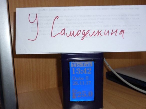
Good afternoon, today I will share instructions on how to make a watch with a room thermometer. The watch runs on Arduino UNO, WG12864B graphic screen is used to display time and temperature. As a temperature sensor - ds18b20. Unlike most other watches, I will not use RTS (Real Time Clock), but try to do without this additional module.
For this homemade The following components are required:
- Arduino UNO (Or any other Arduino compatible board)
- Graphic screen WG12864B
- ds18b20 temperature sensor
- Resistor 4.7 Kom 0.25 W
- Resistor 100 ohm 0.25 W
- Battery compartment for 4 AA batteries “finger-type”
- Suitable box
- Small file
- Nail polish (black or body-color)
- A little thin plastic or cardboard
- electrical tape
- connecting wires
- Circuit board
- Buttons
- soldering iron
- Solder, rosin
- Double sided tape
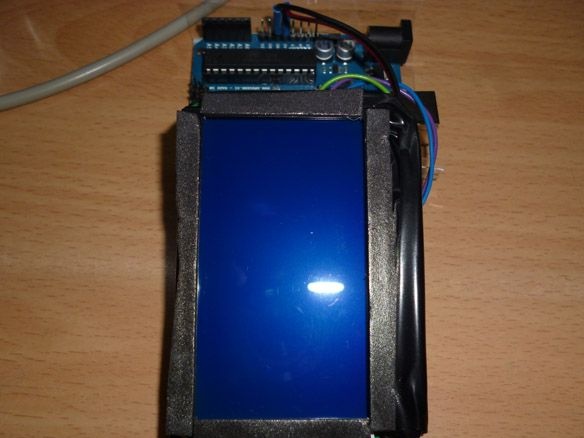
Step 1 Preparing the enclosure.
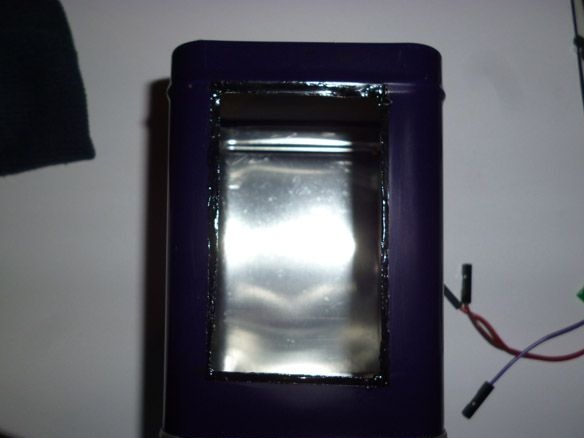
So, our watches should be located somewhere. You need to find a suitable box. The main thing is that the WG12864B screen, Arduino and a small circuit board for buttons fit in it. The minimum box size is 7 x 7 x 10 cm. If you use a small Arduino board, you can shove it into a box and a smaller one, but I will describe the process using the Arduino UNO as an example. The material of which the box is made is preferably plastic, if, like mine, it is iron, it is worth taking care of the insulation so that there is nothing to “go around” inside. Plastic is preferable because it is easier to cut. With a box, he is the case of our watches, decided. Now it is necessary to cut a window under the screen measuring 6.5x4 cm. If the box is iron, it is extremely difficult to do it carefully. No matter how you try, there will be chipped paint and roughness near the cut. Therefore, first we cut it out, for this you can use the “grinder”, a drill with a nozzle for cutting or a milling cutter, in general, of your choice, with what is at hand. After that, we clean the edges with a file. We paint all chipped paint with nail polish, suitable color. The result should be the following:
Step 2 Prepare the graphic screen.
With the connection of the screen, at first glance, many problems and difficulties arise. But if you first deal with their types, it will become much easier and more understandable. There are many variations and types of screens on the ks0107 / ks0108 controller.All screens are usually divided into 4 types:
Option A: HDM64GS12L-4, Crystalfontz CFAG12864B, Sparkfun LCD-00710CM, NKC Electronics LCD-0022, WinStar WG12864B-TML-T
Option B: HDM64GS12L-5, Lumex LCM-S12864GSF, Futurlec BLUE128X64LCD, AZ Displays AGM1264F, Displaytech 64128A BC, Adafruit GLCD, DataVision DG12864-88, Topway LM12864LDW, Digitron SG1286464J-1, QY1286464JF, 2 QY
Option C: Shenzhen Jinghua Displays Co Ltd. Jm12864
Option D: Wintek-Cascades WD-G1906G, Wintek-GEN / WD-G1906G / KS0108B, Wintek / WD-G1906G / S6B0108A, TECDIS / Y19061 / HD61202, Varitronix / MGLS19264 / HD61202
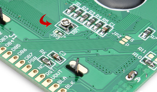
The list is not complete, there are a lot of them. The most common and, in my opinion, convenient WG12864B3 V2.0. The display can be connected to the Arduino via a serial or parallel port. When used with Arduino UNO, it is better to choose a serial port connection - then we need only 3 outputs of the microcontroller, instead of a minimum of 13 lines when connected via a parallel port. Everything is connected quite simply. There is one more nuance, on sale you can find two versions of displays, with a built-in potentiometer (for adjusting contrast) and without it. I have chosen, and I advise you to do the same with the built-in.
This reduces the number of parts and soldering time. It is also worth putting a current limiting resistor of 100 Ohms for the backlight. By connecting 5 volts directly, there is a risk of burning the backlight.
WG12864B - Arduino UNO
1 (GND) - GND
2 (VCC) - + 5V
4 (RS) - 10
5 (R / W) - 11
6 (E) - 13
15 (PSB) - GND
19 (BLA) - through the resistor - + 5V
20 (BLK) - GND
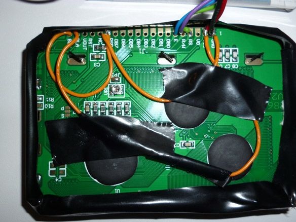
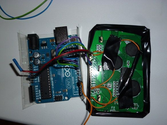
The most convenient thing is to collect everything behind the screen and output 5 wires from it to connect to the Arduino UNO. The result should be something like this:
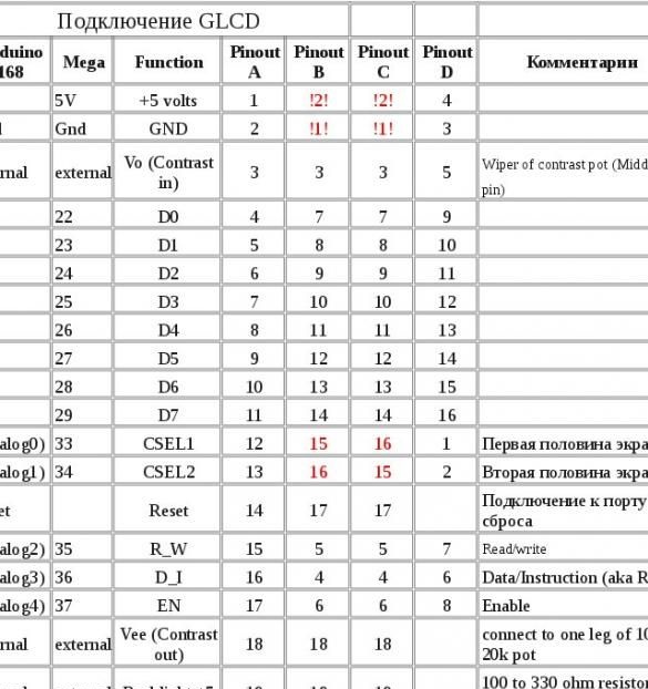
For those who still choose a parallel connection, I will give a connection table.
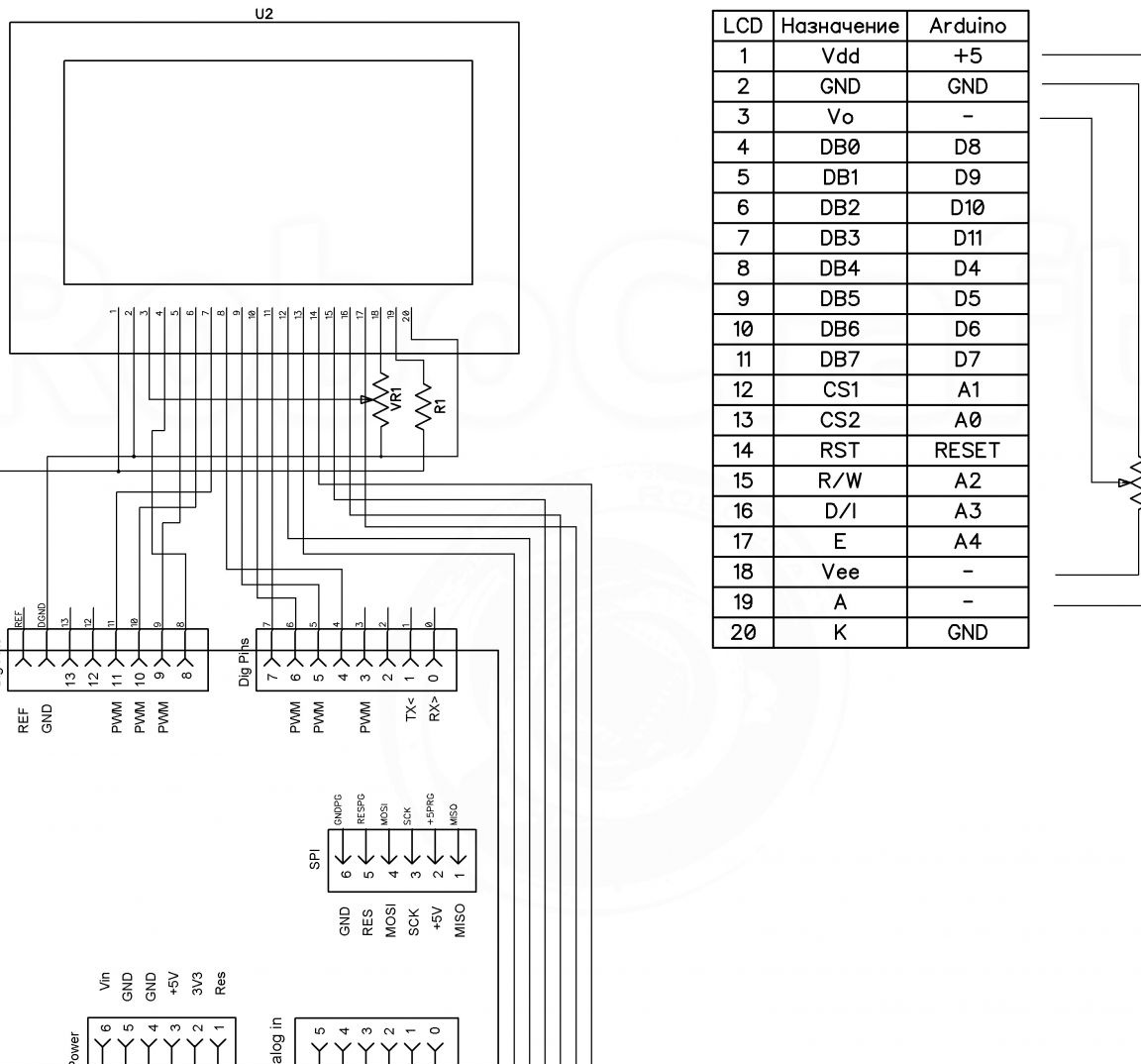
And the layout for option B screens:
Step 3 Connect the temperature sensor.
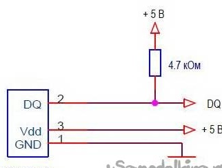
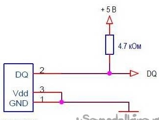
As I said, we will use the DS18B20 integrated sensor to measure temperature. I chose it for its high measurement accuracy, the error is not more than 0.5 ° C. The sensor is calibrated at the time of manufacture; no additional settings are required. Temperature measurement range -55 ... + 125 ° C. There are two modes of operation: with an external power source and “spurious power”. When operating in external power mode, the connection is as follows:
When using "spurious power" the sensor receives power from the communication line. In this mode, two wires are enough to connect the ds18b20 to the microcontroller. The internal capacitor of the sensor is charged due to energy on the communication line at a low level on the bus. The "parasitic nutrition" mode has many features and therefore I do not recommend using it. But if you still decide to use it, here is the diagram:
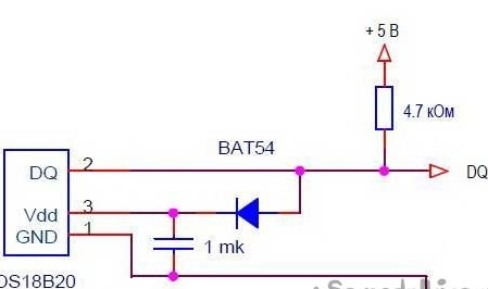
Or you can use an improved wiring diagram when using "spurious power":
Several sensors can be included on one communication line. For our watches one is enough. We connect the wire from the “DQ” ds18b20 pin to the “pin 5” Arduino UNO.
Step 4 Preparing a board with buttons.
To set the time and date on the watch, we will use three buttons. For convenience, solder the three buttons on the circuit board and wire out.
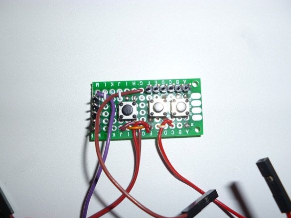
We connect as follows: the wire common to all three buttons is connected to the “GND” Arduino. The first button, it serves to enter the time setting mode and switch over time and date, connect to "Pin 2". The second, the button for increasing the value, goes to “Pin 3”, and the third, the button for decreasing the value, goes to “Pin 4”.
Step 5 Putting it all together.
To avoid a short circuit, insulate the screen. In a circle we wrap with tape, and on the back we fasten to a double-sided tape, cut to size, a strip of insulating material. Thick cardboard or thin plastic is suitable. I used plastic from a paper tablet. It turned out the following:
On the front of the screen along the edge we glue a double-sided tape on a foam basis, preferably black.
We connect the screen to Arduino:
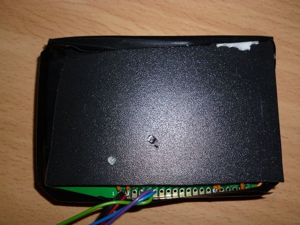
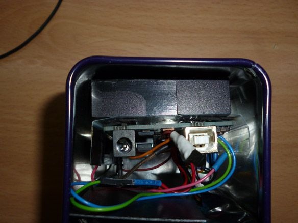
Plus we connect from the battery compartment to the “VIN” Arduino, minus to the “GND”. We place it behind the Arduino. Before installing in the case, do not forget to connect the temperature sensor and the board with buttons.
Step 6 Prepare and fill the sketch.
A temperature sensor needs the OneWire library.
The output to the screen is through the U8glib library:
To edit and fill the sketch, install these two libraries. There are two ways to do this. Just unzip these archives and place the unzipped files in the “libraries” folder located in the folder with the Arduino IDE installed.Or the second option is to install the library directly in the programming environment. Without unpacking the downloaded archives, in the Arduino IDE, select the Sketch - Connect Library menu. At the very top of the drop-down list, select the "Add .Zip Library" item. In the dialog that appears, select the library that you want to add. Open the Sketch - Connect Library menu again. At the very bottom of the drop-down list you should see a new library. Now the library can be used in programs. Do not forget to reboot the Arduino IDE after all this.
The temperature sensor works according to the One Wire protocol and has a unique address for each device - a 64-bit code. Each time, looking for this code is impractical. Therefore, you must first connect the sensor to the Arduino, fill in the sketch located in the File - Examples - Dallas Temperature - OneWireSearch menu. Next, run Tools - Port Monitor. Arduino should find our sensor, write its address and current temperature readings. We copy or simply write down the address of our sensor. Open the sketch Arduino_WG12864B_Term, look for the line:
byte addr [8] = {0x28, 0xFF, 0xDD, 0x14, 0xB4, 0x16, 0x5, 0x97}; // address of my sensor We write down the address of your sensor between braces, replacing the address of my sensor.
Stock:
//u8g.setPrintPos (44, 64); u8g.print (sek); // Print seconds to check the correctness of the courseDisplays seconds next to “Data”. This is necessary to accurately set the course of time.
If the clock is in a hurry or lagging, you should change the value in the line:
if (micros () - prevmicros> 494000) {// change to another for correction was 500000I experimentally determined the number at which the clock goes quite accurately. If your watch is in a hurry, you should increase this number; if I am behind, decrease it. To determine the accuracy of the course and need a conclusion seconds. After accurately calibrating the number, seconds can be commented out and thus removed from the screen.
Fill the sketch.