The advantages and disadvantages of lamp circuits of amplifiers of low (sound) frequency, a lot of controversy. There are, after all, whole separate streams of lamp sound, with their gurus and adepts. “Only lamps, no semiconductors”, “hybrid”, “single-cycle”, “fans of transformers (interstage)” and hybrids and subspecies. This applies to the masters, who in any case deserve respect. There are also those for whom the fooling of their neighbor is a profession. It’s very bad there. Of course, everywhere there are exceptions.
We will not touch on “theology” now, but let's see what we managed to make from literally trash.
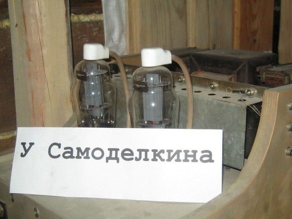
Perhaps it’s worth starting with the fact that we came to the Perm Territory to look for a place to live, mainly with the most necessary things and radio components were not included. Fortunately, in the city there was a small store selling radio components, with a peculiar assortment, however, and what was discovered was for happiness. The radio elements required for an amplifier on lamps are somewhat specific, this is not counting the radio tubes themselves. In a word, having lost his mind, he advertised in a local newspaper about the purchase of a tube radio. They called a lot, gave a few for no reason, with the condition “pick-up-the garage“to myself.” Four pieces were accumulated, then relatives rebelled, and it was embarrassing to insist - we then temporarily lived with our parents, and I made with my grandmother in the private sector. Fortunately, two radios turned out to have very close interiors - a typical 6P14 bass amplifier circuit, and the power supply is the same. "Our Alena Igorevna, looks so typical-typical."
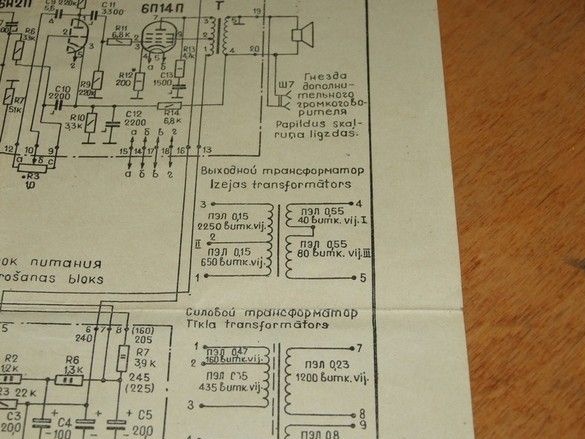
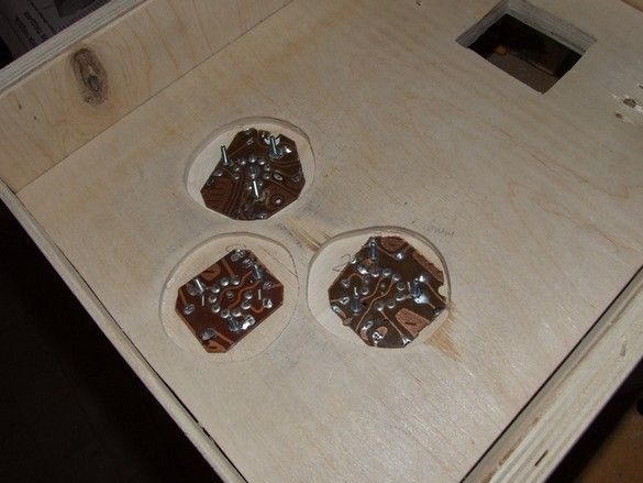
The first treacherous thought that I could hardly strangle with a pillow was just to take and transfer these amplifier boards to a separate box and ... and that's all. But firstly, it would not be too aesthetically pleasing (But what about the main highlight of the lamp from the outside? Vypendrezh of course, but it's beautiful after all). Yes on printed circuit boards - well, no. In a word, it was decided to give up the easy way; tea is not the first time we smell rosin! So that everything is like people ... (singing under my nose) everything is like people-e-e. Yes, hmm, well, I laid out the lamps pulled from the radio on a workbench on a rag, sketched a diagram, a power supply, so that all the voltages are stabilized, all things. 6P14 output lamps, triode-pentode switching, output transformers, such as TVZ 1-9, input stage 6N2P, but left the statement for later, after the experiments.
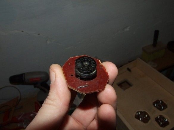
Decent lamp ceramic panels in the store and never seen before, had to get out.
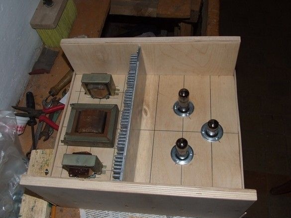
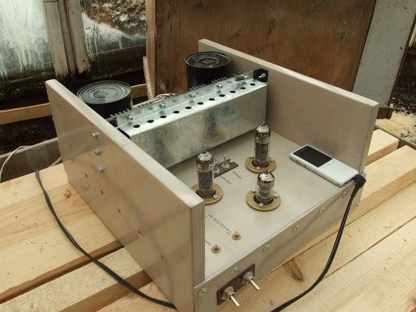
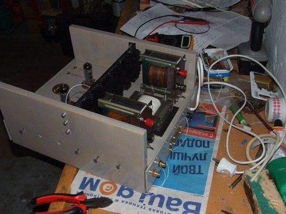
High side walls, only partly for simplicity. Largely for convenience - it does not badly protect fragile and struggling radio tubes, and given the upcoming construction in the village, it is generally not clear where the device will be lugged. Again, it’s very convenient to tune and remodel - turned it over and stands at a loss, and you do not need to pull out the lamps either - solder, measure, turn on as much as you like.
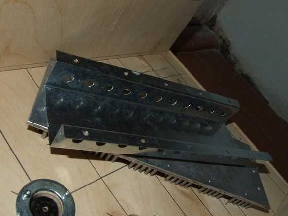
Radiator on top for stabilizers, high voltage and heat. Rectifiers for them in the basement of the chassis.
The case is disassembled, putty, grinding, a couple of layers of paint.
The body assembly is full.
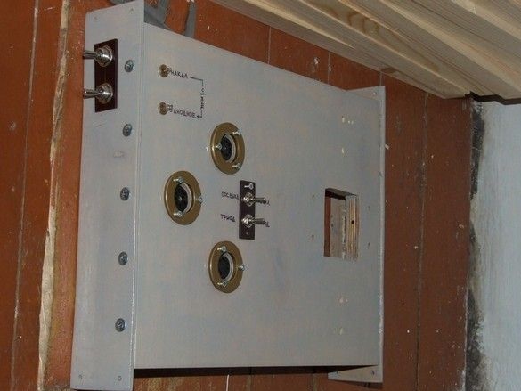
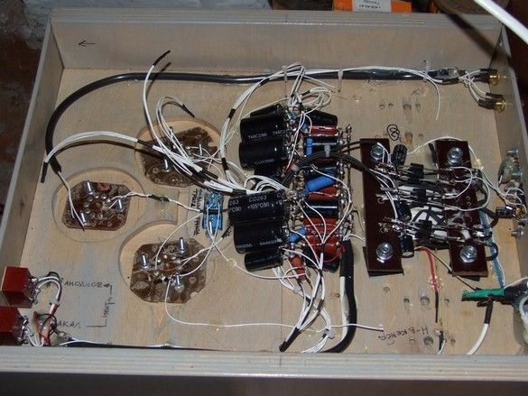
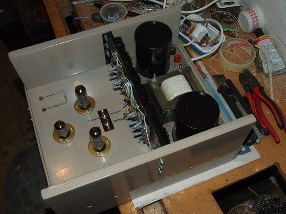
Mounted power on toggle switches (glow and delayed anode), power indicators on neon bulbs, lamp panels, output stage mode switches - triode pentode, and feedback enable.
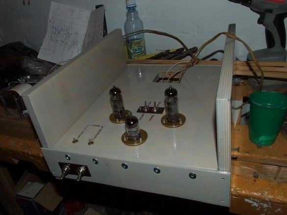
Rectifiers are installed in the basement, a fuse on the back wall in the fixture, everything is connected, carefully check the operation of the finished piece of the circuit directly from the network. Lamps stick out for entourage.
Everything works, cheers.
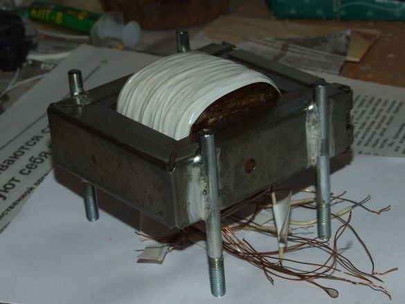
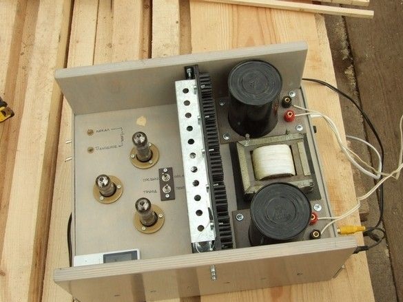
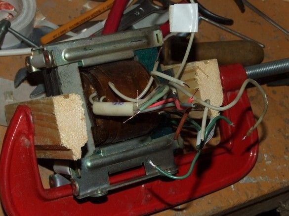
Queue for power transformer. This one, from the same radio. Power should be enough. The casing was removed from the magnetic circuit, four studs from long M6 bolts were soldered to it. For installation sideways in a lying position, so that all the wires are in the basement of the chassis. Boil the coil in varnish so as not to hum.
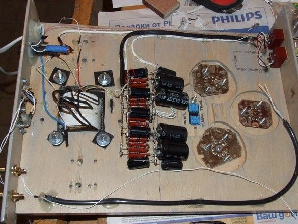
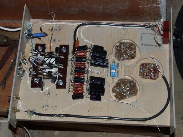
High-voltage rectifiers are mounted and already tested, there are already four of them - for each stage of two channels its own. Each diode is shunted by a film capacitor against interference during switching.
Electrolytic capacitors here, including from stabilizers. The stabilizers themselves will be on top of the radiator.
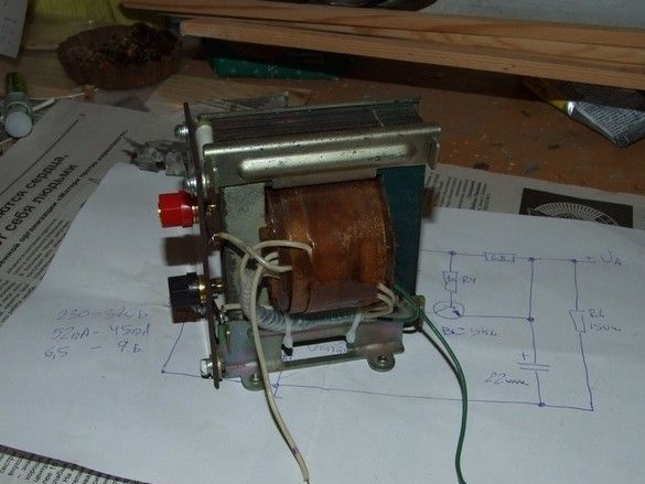
Power on toggle switches and neon indicator lights are connected. You can see the signal jacks and the shielded cable to the first stage.
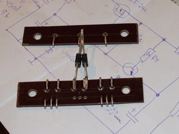
Planck, there is no Picatinny - Masaya. Contact. It will be mounted on the transformer screws inside the case. On it, the rectifier diodes of all the lamps are conveniently soldered. Stabilizers, again outside on a common radiator.
Stabilizer +5 volts. With a USB jack. For the convenience of MP3 player. So as not to run looking for a charge or computer. Normal 7805, in the classic inclusion - two electrolytic, two ceramic capacitors. It is powered by a rectifier.
Oh, the transformer is in place. Charging too. The contact strips are jammed onto the transformer fasteners, three diode bridges with electrolytes are soldered to them, charging for the MP3-shnik is turned on.
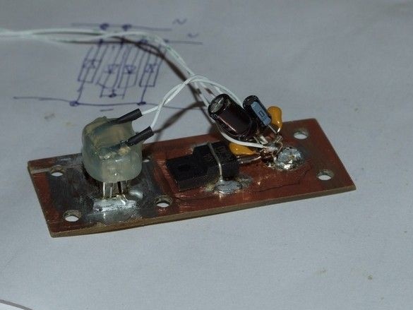
Scarf with stabilizers. High-voltage on discrete elements, three stabilizers of glow in the middle - at 7806, plus, one or two (pick up) diodes in the general output.
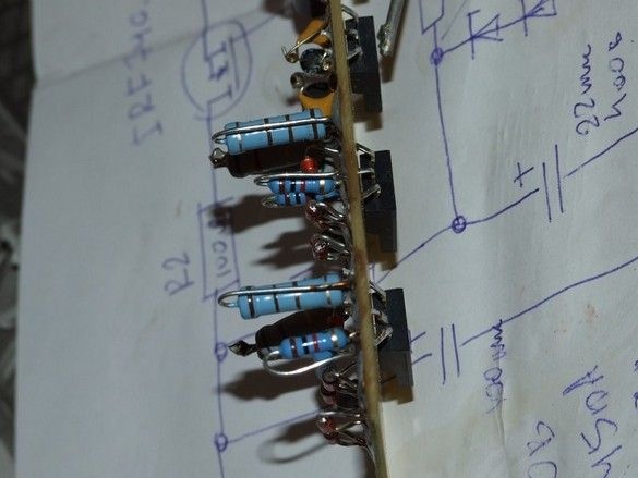
On the other side of the board are power elements.
Moreover, in order to press them with their backs to the radiator. The board was also made in a somewhat original way - in the same way as with SMD elements, so that there are no tracks or conclusions on the radiator side. High voltage all the same.
That’s the way.
The cover is understandable from above so that fingers can not get into high voltage. The radiator is standard, needle, the cover is made of 0.5mm galvanized steel roofing.
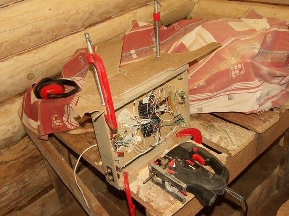
BP tests. Connections between rectifier and stabilizer on a live thread.
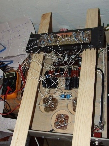
The most difficult thing is to put it into place and install it. Radiator with stabilizers on the other side of the chassis. All wires collected in four bundles are threaded into the holes and held to the rectifier. With tweezers, with a bit of patience and attentiveness. Then the main fun begins - to look for a tester where which end of the wire and connect in two circuits, so that nothing extra sticks out, so that "and look do not confuse ... Kutuzov." And not that the salute can be noble, swam, we know.
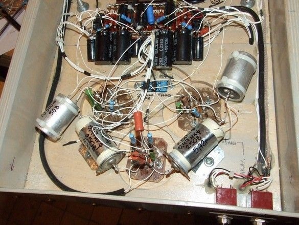
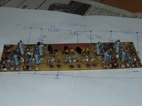
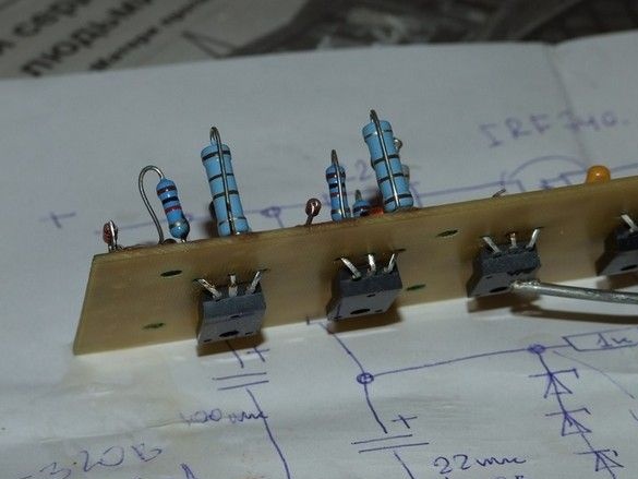
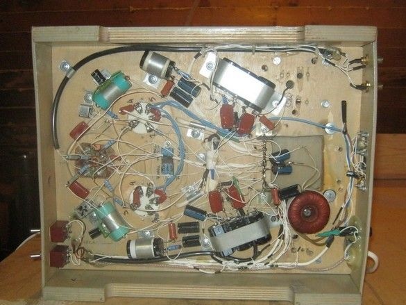
These are the cascades of amplification themselves, by their own person, so to speak. Well, everything is like people. Auto-bias, interstage capacitors like PTFE, we’ll be curious.
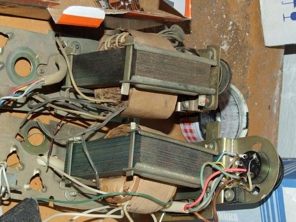
Output transformers.
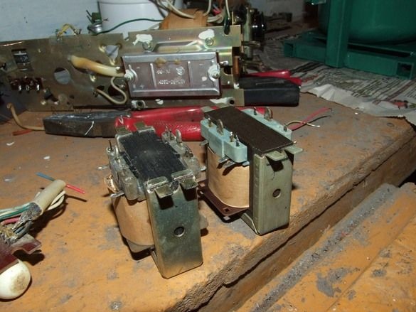
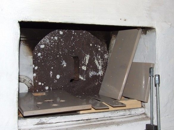
From the radios it’s clear that they are boiled in wax with paraffin, the hot core is pulled in a vise through a strip of gum - so that the non-magnetic gap in each layer of iron is the same and minimal.When disassembling, we do not lose a strip of paper for a non-magnetic gap.
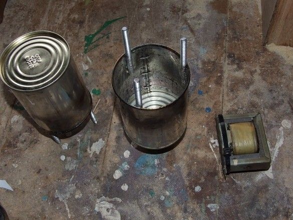
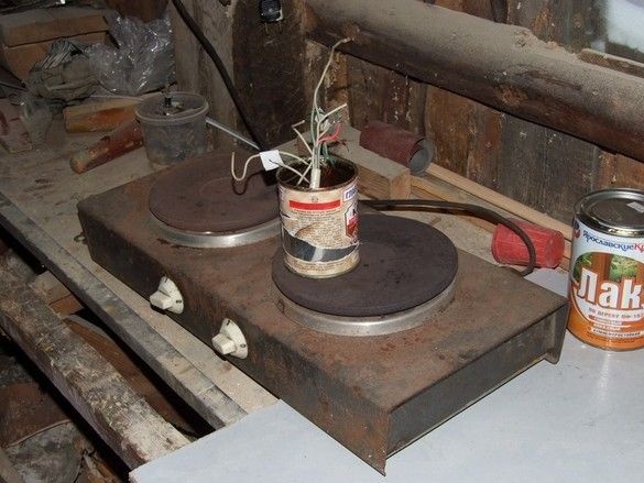
And in an improvised casing from a condensed milk can.
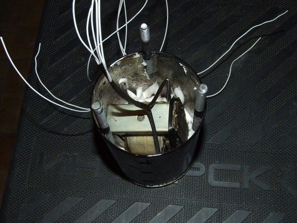
Fill with wax, or neutral sealant, or epoxy, if not sorry.
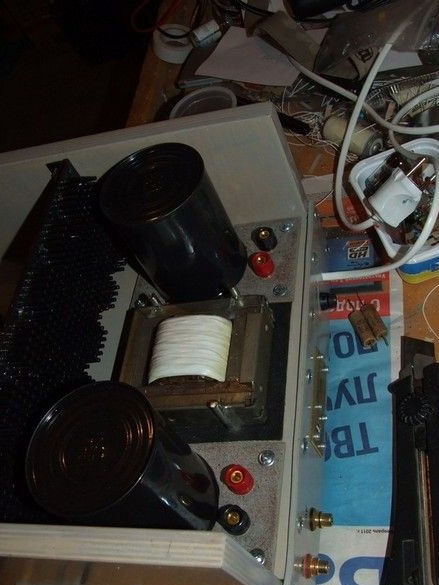
Output transformers in place.
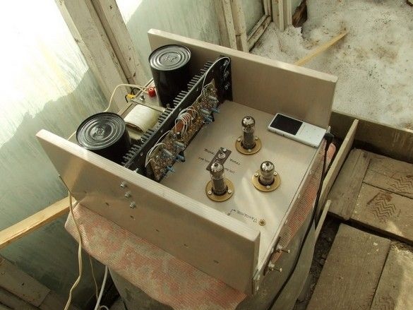
Listening in the grandmother's greenhouse, where there are more places. What I like.
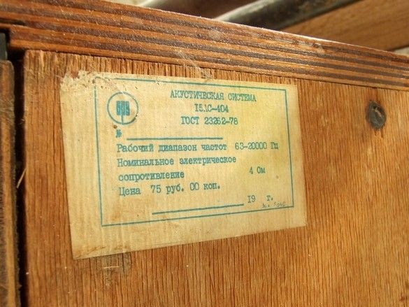
The acoustics were such, the acoustic design - the “closed case”, plays well, but the sensitivity is not enough, you have to basically turn on the output stage with a pentode.
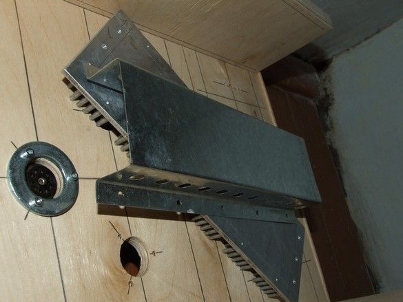
This is with a casing on the radiator.
After working for some time, one of the output transformers burned out, I had to redo it for others.
Boiling the coils in varnish (as it turned out later, in vain).
Pulling the magnetic circuit through an elastic band, for the same gap in the layers of iron. Do not forget the paper core in the core. Well, the plates are not going to "overlap", and so - E gasket I.
Output transformer assembly.
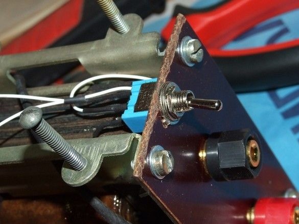
The transformer brackets formed a sort of basement, perfectly fit into it on a small toggle switch including feedback.
In this form, the amplifier worked for about two years. There were no significant comments on him.
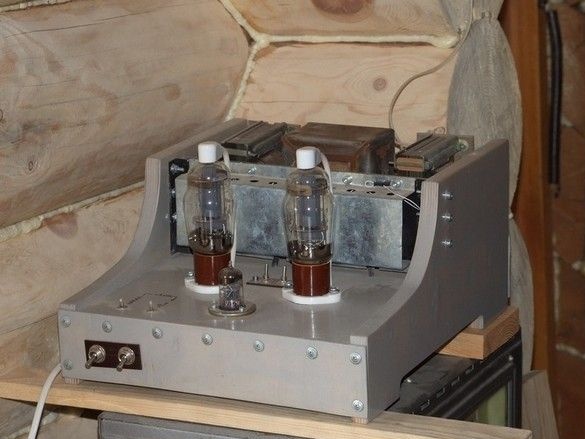
The next incarnation of the amplifier in a few years. A pair of g-807 lamps with sockets and anode caps fell into the hands.
At the same time, it was decided to somewhat soften the square-nested design. A couple of templates for a milling machine are made, side panels are milled. Anyway, the role of a convenient stand when turning over and protecting the lamps is partially lost - the lamps are hefty and cheeky stick out through the fence.
The power transformer has been replaced by a more powerful one, a fixed offset of the output stage, a power source for it have been introduced. The rectifiers and voltage stabilizers are removed - the G-807 is too powerful, 7806 can not cope.
Updated look.
It plays well, as far as the speaker allows it to be judged. Recent changes were made more than 5 years ago. The amplifier works in the workshop, about a third of the day every day.