

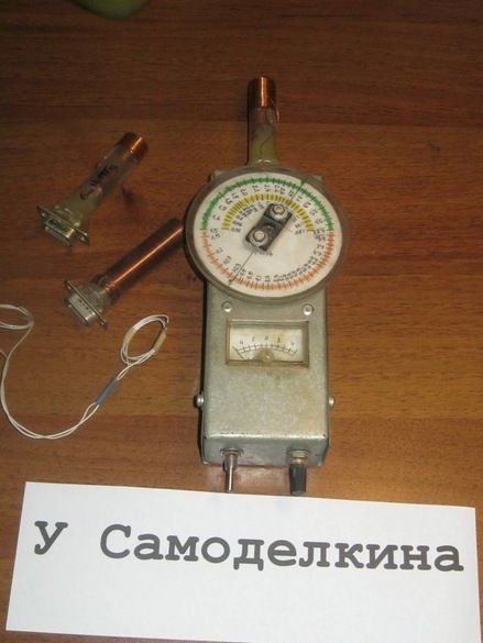
When designing and tuning radio equipment, such an ingenious device as a heterodyne resonance indicator is very useful. The device, in most cases, is quite simple and can be made even by a novice radio amateur.
It is used mainly for measuring the resonance frequency in the oscillatory circuits of radio equipment. Using GIR, you can also measure the capacitance of the capacitors and inductance of the coils, measure the resonance of the antenna.
Heterodyne - means generating high-frequency oscillations. At the RF generator of our device, the coil of the oscillating circuit is brought out and made in the manner of a kind of probe. The measurement principle is based on the fact that when two closely spaced loops are tuned to one frequency, they enter into resonance and a “suction” of vibration energy from one loop to another is observed. Tunable oscillation circuit of the GIR - has a variable capacitor with a graduated scale.
To determine the resonance frequency of the circuit under study, the GIR coil (or coupling coil) is brought to the circuit and by changing the frequency of the device, the indicator readings are minimized. The setting is pretty sharp. A kind of failure of the arrow indicator. The desired frequency is read from the scale.
The device was manufactured according to the simplest scheme published in the journal "Radio" No. 3 of 1975. Author V. Borisov.
Assembling a circuit does not cost anything, but in order for the device to be convenient to use, you will have to tinker.
We will need.
Instruments.
The minimum set of bench tools mainly for small jobs, metal scissors, a few different files. Markup tool. It would be nice to have a jewelry jigsaw or engraver - for cutting windows in the case, but you can do it. Jigsaw "pioneer", wood, plus a dovetail stand for cutting. You need something drilling - an electric drill or a drilling machine, and a screwdriver will do. In individual cases, rivets with the appropriate tool for their installation may be useful.
A small soldering iron and everything that is supposed to be with it, including a set of tools for electrical installation. Soldering iron with a power of about 75 ... 100W, for structural soldering. In some places, an adhesive gun is convenient. A little patience and accuracy.
Materials
In addition to radioelements, you need a little roof galvanized steel, a piece of plexiglass and fiberboard or textolite.A few small hardware. Plastic frames for interchangeable coils.
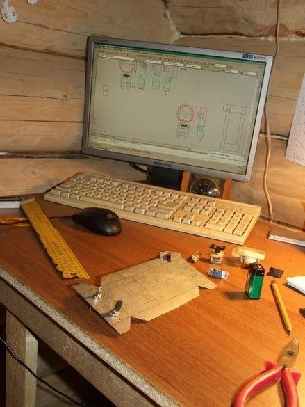
To begin with, it is worth picking up all the radio elements and knowing their dimensions to deal with the layout of the device. It is convenient to do this in CAD AutoCAD. For home, hobby use, it is enough to master the principle of construction and several basic tools.
It was decided to make the casing of the device from 0.5 mm galvanized steel roofing, by bending from two U-shaped parts. The metal case also shields the circuit well. The windows in the case for the installation of devices, connectors, were sawn by an engraver with a cutting disc. It will also be convenient to use a jewelry jigsaw.
In this version of the GIR - the connector for interchangeable coils must have at least three contacts (a coil with a tap is used). To reduce the dimensions of the device, it was decided to use DB-9, similar to the COM port connector on the computer system unit. It is supposed to use an indicator in the circuit - a microammeter for a current of 50 μA. Such a device has significant dimensions. Significantly smaller microammeters used to indicate the recording level in old magnetic sound recording equipment. To be able to use such an indicator, it is necessary to add an amplifier stage on a low-frequency transistor to the original circuit of the device (circuit b). The indicator itself was disassembled, replaced the standard scale with a homemade one with zero in the middle.
The variable capacitor is applied with a solid dielectric, from an imported radio receiver.
A metal box is made. Two halves of the case are fastened with four M4 screws. Gadgets are soldered on the inner walls. Galvanized steel is soldered well with ordinary tin-lead solder with "soldering acid" (zinc chloride). Do not forget to rinse the rations well.
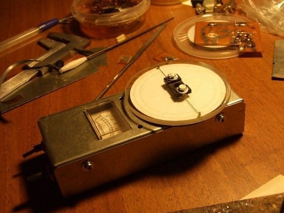
A pen-scale, carved from a piece of organic glass, is put on a capacitor.
A circle of the desired diameter is drawn on the blank. This can be done with a compass, a marking compass (with two needles). Also, for plexiglass, it is convenient for such a purpose to use a vernier caliper, fix the required size with a locking screw and draw with sharp paws for measuring holes.
The workpiece was sawn off with the usual "pioneer" jigsaw. The edges are polished with a grinding sand, for this the workpiece was clamped in a screwdriver.
Inside, on a transparent disk, two deep radial risks are made and filled with paint. Small holes were drilled at the tips for convenient marking of the scale - in the right places marks are made with a needle or sharpened pencil. It is mounted on the axis of the capacitor by its standard fasteners from the same radio. Under the movable transparent disk, on the same axis as it, is a fixed disk made of fiberboard fixed to the body. The diameter is slightly smaller than transparent, so that the movable disk is conveniently rotated with the thumb while holding the device in hand. The disc is sawn with a jigsaw and coated for durability with several layers of varnish. A paper scale is glued to it.
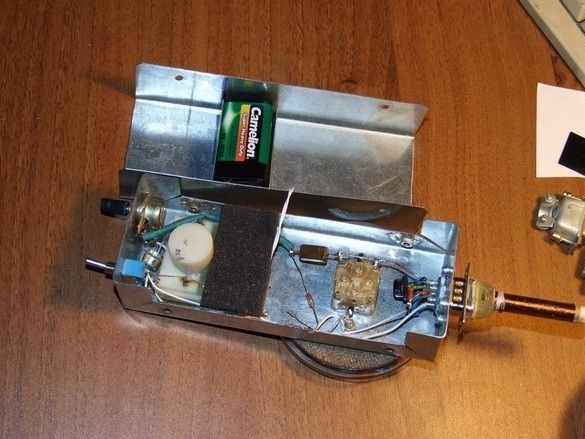
Installation of small elements on the installation leads, the leads are as short as possible, especially in the RF part. The “Krona” battery is located inside the device’s case; it is connected by a block from the same failed one. To prevent it from floundering inside the case on the wires, a certain “battery compartment” was made - a C-shaped part from the same roofing steel. Soldered to the removable lid. Opposite the battery, a piece of foam, when collecting the case, it presses the battery. In the photo, the first version of the coils.
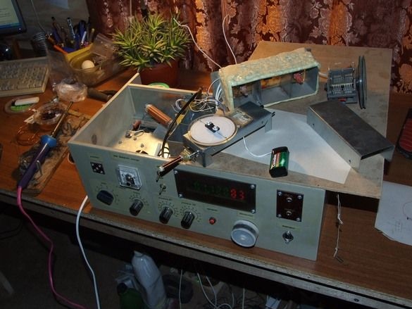
Using a local oscillator homemade radio equipped with a frequency meter, the scale is graduated. Calibration can also be done using a frequency meter, an RF generator, a standard signal generator (GSS), and finally, using an HF radio with an accurate scale.
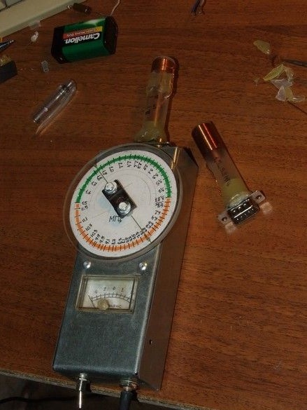
The device is complete, with two interchangeable coils made of disposable syringes using hot melt adhesive.
If it is necessary to measure in the range of hundreds of kilohertz - units of megahertz, the design of the replaceable coil should be applied similar to the magnetic antenna of a radio receiver, on a piece of a ferrite rod.
To measure the resonance frequency of a parallel oscillatory circuit, you need to turn on the GIR power supply, use the variable resistor knob to set the indicator arrow to zero (the middle of the scale) and, as close as possible, the GIR coil of the expected range to the coil of the circuit under study, and slowly and smoothly rotate the variable capacitor dial. At the same time, carefully monitor the indicator arrow. When changing the frequency of the GIR, the arrow will make small fluctuations, but at the moment of resonance, there will be a strong failure. At this point, the frequency on the GIR scale will correspond to the resonance frequency of the investigated oscillatory circuit.
If it is impossible to bring the GIR coil closer to the test one, we manufacture and use the communication coil. Several turns of a thin mounting wire around the GIR coil are connected to several turns around the studied coil.