

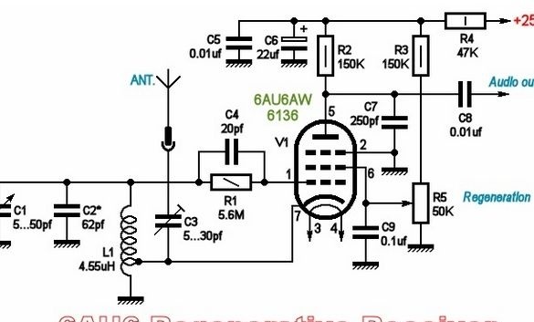
The proposed scheme is very simple, contains only one electronic a lamp.
True, the radio does not contain a low-frequency amplifier and loudspeaker. All this is supposed to be external. You will also have to take care of the power source - anode voltage and glow. To obtain high characteristics of the radio, it is better to stabilize these voltages. This is not at all difficult. Transformers with a boosting secondary winding are now rare, few people like to reel coils, so you can do the following. Two transformers of the same type with connected secondary windings will solve this slight difficulty. At the output of the second transformer we get the same 220V, with galvanic isolation from the network.
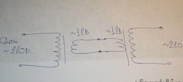
Using transformers with different secondary windings, you can get the desired voltage at the output.
As a ULF, you can use an active speaker system from a computer.
In the author's version, a homemade tube amplifier was used. From it, the voltage of the glow and the anode were taken. The radio was connected to the amplifier with two connectors - a signal, standard pin with a diameter of 3.5 mm. and high voltage with a glow, a DB-9 connector, on the “mother” source (amplifier), so that there are less chances to get your fingers inside.
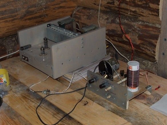
The radio was assembled on a retro chassis, with a basement, mounted mounting. Such a design was widespread in the era of lamp circuits and was very convenient - there are many large-sized installation elements, between their hard terminals in the basement the wire leads of resistors and capacitors are soldered. Whoever does not have enough space, contact strips are installed. The advantages of this kind of installation are fewer (at least compared to the printed circuit) parasitic capacitors and interference, but with maintainability is not brilliant.
So what was required.
First of all, radio elements. Of the not the most common, you still need a capacitor of variable capacitance with an air dielectric for the oscillatory circuit of the radio receiver. You should not use common miniature solid-state capacitors with solid dielectric from imported radios and radio tape recorders - the frequency stability will be low and the tuning of our radio will “float”. Look in the old tube radios, good, they are still a lot in the attics and garages.
It is hardly at hand that a capacitor of variable capacitance is exactly the same as in the diagram. To get out of the situation, you can re-read the oscillatory circuit. It is convenient to do this with the help of special programs, for example Coil 32. Among other things, it will give a certain degree of freedom in the manufacture of an inductor - you can have a good finished coil on hand from a connected technique different from that indicated in the inductance circuit or just need to rebuild the radio to a different range. The program also allows you to calculate the coil for the desired inductance.
In the calculation, one should strive for larger values of the diameter of the wire, and the winding pitch, this will allow to achieve a higher quality factor of the circuit. By the way, much depends on the design of the coil (the initial quality factor of the circuit) in the regenerators. This is a fee for the simplicity of the overall design.
Instruments.
It was this radio that was made literally “on the knee”, with a minimum of tools - an ordinary set of locksmith tools, mainly for small work, metal scissors. Something for drilling holes, a wood jigsaw and a jewelry jigsaw with files are useful. Individual elements were fixed with hot-melt adhesive.
Soldering iron about 40W with accessories, a set of tools for installation.
Materials
In addition to the radio elements, a piece of fiberboard was used for the upper panel of the chassis, small pieces of galvanized steel roofing for corners, brackets and auxiliary elements, a larger piece for the front panel. Pieces of wooden slats and planks, some fasteners. Something suitable for the body of the contour coil, preference should be given to ceramics and polystyrene, an empty “syringe” from silicone sealant is used here. Coil wire in varnish insulation for the coil.
In addition to the above, you will also need an antenna and grounding.
In the author's version, the L-shaped antenna was made of a bundle of winding wire - about 10 cores ~ 0.25 mm. It is stretched between four insulators made of porcelain “coils” (on which, during the time of Ilyich’s bulb and electrification, all countries installed electrical wiring), in the attic, under the ridge of the slate roof, a reduction was brought into a log house. There are more insulators (here, two on each side) - the more there are, the more weak the signal the antenna can receive. The suspension height of the horizontal part, a little more than 7m, its length is 9m.
In a dry attic, porcelain rollers or nuts can perhaps be replaced with a nylon cord. Although the rest, the location of the antenna under the roof, albeit not metal, is not the best option.
The grounding was made of a meter-long steel strip pointed at one end and hammered into the ground near the house. An M6 bolt was welded on the other end. Between the two enlarged washers, the tinned end of the copper braid was sandwiched. Last, brought into the house.
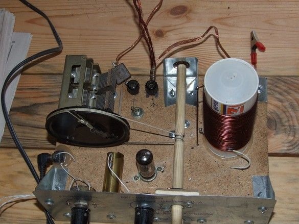
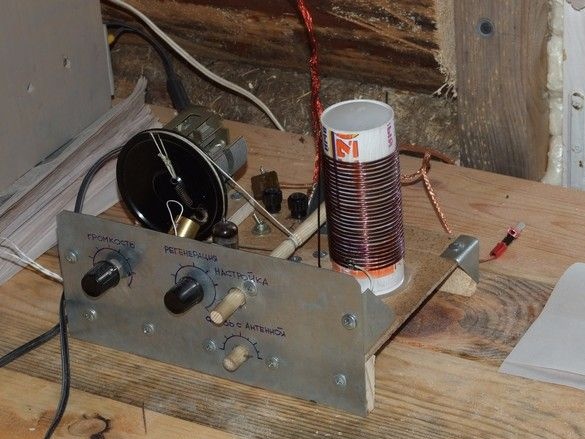
The design of the radio is visible in the photo. The upper panel is made of fiberboard, front and rear, two legs-stands from a pine lath are installed, fixed with small cloves with glue. From galvanized steel, the front panel is cut and fixed with the help of corners and screws.
The upper panel has large elements. A capacitor of variable capacity was found with its own special pulley (with a groove for the rope and a spring for its tension), the rope was taken from it. The capacitor was mounted on a small wooden stand - otherwise the pulley did not fit, but it was possible to saw a gap into the basement with a jigsaw.
For convenient adjustment, a vertical with a fair deceleration is applied. Verenier shaft made of round wooden sticks, improvised bearings made of thin plastic from a bottle. Unfortunately, the Vernier design was not very successful, the adjustment shaft had to be rotated, albeit with a small but still effort - the friction of the wooden shaft pressed by the tensioned cable to the wooden gasket from the inside of the front panel was great. Perhaps, having disassembled the vernier, rub the rubbing parts with stearin candles or, better, replace the shaft with a metal shaft, polishing it in the place of contact. And make the sleeve of ftoroplast. However, I repeat - the design was "knee-high."
The coil is wound on the body of an empty "syringe" from silicone sealant. The tube is cut to the required length, the plug-piston is elongated with a long self-tapping screw. Turning it over, we insert it from above, flush with the edge - a rather thin plastic tube at the same time acquires somewhat greater rigidity and looks more aesthetically pleasing.
We cut off the plastic nozzle attached to the sealant tube to the thread and use it as an impromptu nut. In addition, the coil body is glued to the top panel with hot glue.
The tap from a part of the turns of the coil, when performing the winding with a sufficiently thick wire, is more convenient to solder by scratching with a sharp blade a small area of varnish on the wire. The number of turns “before” the tap is selected experimentally. This should be the place at which the generation approach is the smoothest (starting halfway from the bottom). Generation ("whistle") should begin at about 90% of the potentiometer slider to the 150K resistor, which is the top one in the circuit. If it starts earlier, the approach is too harsh and as a result it is not possible to stretch out the maximum sensitivity and selectivity.
A very close analogue of the "industrial-military" 6136 - 6Zh4P-DR, but the usual one, without indexes, also works as pretty. The use of a screen for a lamp - a sleeve rolled out of brass foil connected to the “case” of the circuit somewhat reduces interference.
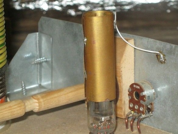
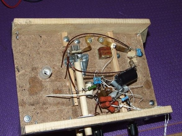
Installation was carried out mainly by own conclusions of radio elements. The remaining several connections are made by the same thick winding wire, which was used when winding the coil. Here in the basement, on a special bracket, there is a small capacitor of variable capacity regulating communication with the antenna. I found one with an air dielectric, I think the usual trimmer made of ceramics will work quite well. The capacitor is located in a place where minimum connection lengths are provided. The ability to control from the front panel - an elongated shaft.
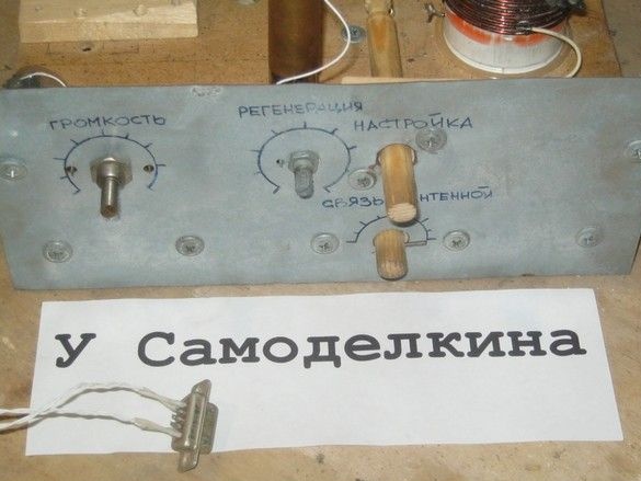
The inscriptions and scales on the front panel are made with an alcohol felt-tip pen for simplicity.