

In this article, the Wizard guides us through all stages of battery assembly, from material selection to final assembly. Radio-controlled toys, laptop batteries, medical devices, electric bicycles and even electric cars use batteries based on a 18650 battery.
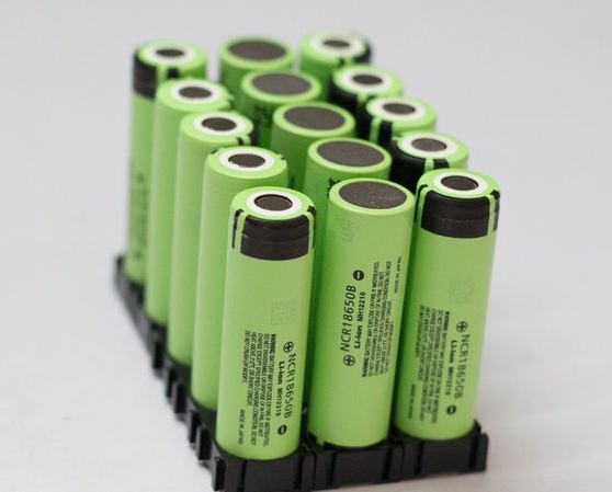
The 18650 battery (18 * 65 mm) is the size of a lithium-ion battery. For comparison, ordinary AA batteries have a size of 14 * 50 mm. Specifically, the author made this assembly to replace the lead-acid battery in his previously made homemade.
Video:
Tools and materials:
-;
-;
-;
-;
-Switch;
-Connector;
-;
- Screws 3M x 10 mm;
-Apparatus for spot resistance welding;
-3D printer;
-Stripper (tool for removing insulation);
-Hair dryer;
-Multimeter;
-Charger for lithium-ion batteries;
-Protective glasses;
-Dielectric gloves;
Some tools can be replaced with more affordable ones.
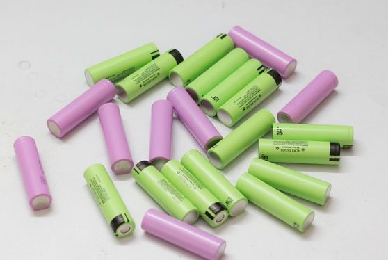
Step One: Battery Selection
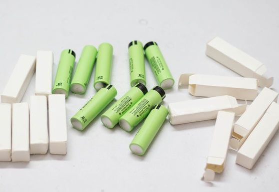
The first step is to choose the right batteries. Different batteries from $ 1 to $ 10 are available on the market. According to the author, the best batteries are from Panasonic, Samsung, Sanyo and LG. At a price they are more expensive than others, but have proven themselves to be of good quality and characteristics.
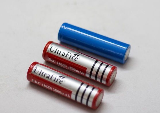
The author does not recommend buying batteries with the names Ultrafire, Surefire, and Trustfire. These are batteries that did not pass quality control at the factory and were bought at a bargain price and repackaged under a new name. As a rule, in such batteries there is no declared capacity and there is a risk of fire during a charge-discharge.
For his homemade master used Panasonic batteries with a capacity of 3400 mAh.
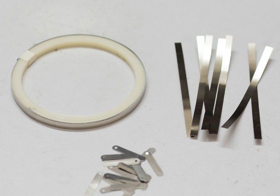
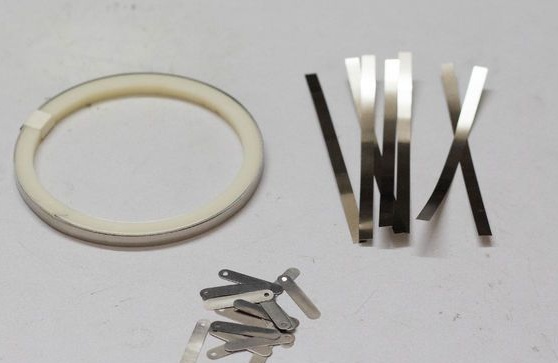
Step Two: Nickel Strip Selection
To connect the battery you need nickel strips. Two products are on the market: nickel-plated metal and nickel strips. The author advises using nickel stripes. They are more expensive, but have a low resistance and therefore heat less, which affects the battery life.
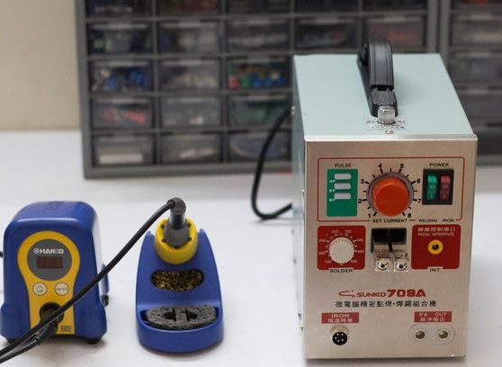
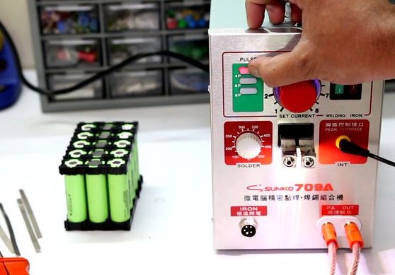
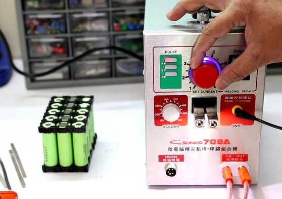
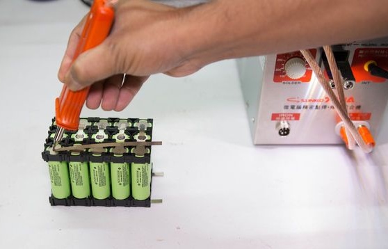
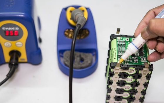
Step Three: Spot Welding or Soldering
There are two ways to solder and spot weld to connect batteries. The best choice for spot welding. In spot welding, the battery does not overheat. But the apparatus for welding (such as that of the author) costs approx. 12 tr in a foreign online store and approx. 20 tr in the Russian online store. The author himself uses welding, but prepared several recommendations for soldering.
When soldering, minimize contact between the soldering iron and the battery.It is better to use a powerful soldering iron (from 80 W) and quickly solder than to heat the place of solder.
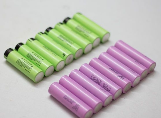
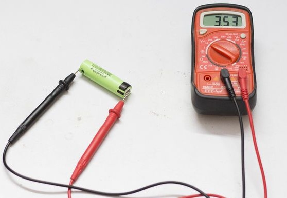
Step Four: Battery Test
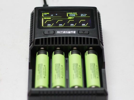
Before connecting the batteries, you need to check each of them separately. Battery voltage should be approximately the same. New high-quality batteries have a voltage of 3.5 V - 3.7 V. These batteries can be connected, but it is better to equalize the voltage with a charger. For used batteries, the voltage difference will be even greater.
Step Five: Battery Calculation
For the project, the master needs a battery with a voltage of 11.1 V and a capacity of 17000 mAh.
The capacity of the 18650 battery is 3400 mAh. With a parallel connection of five batteries, we get a capacity of 17,000 mAh. Designate such a connection P, in this case 5P
One battery has a voltage of 3.7 V. To get 11.1 V, you need to connect three batteries in series. Designation S, in this case 3S.
So, to obtain the necessary parameters, you need to connect three sections, each consisting of five parallel-connected batteries, in series. Package 3S5P.

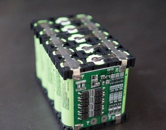
Step Six: Battery Assembly
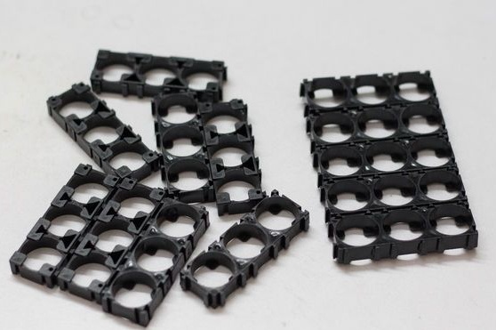
To assemble the battery, the master uses special plastic cells. Plastic cells have several advantages over connecting them, for example, using a glue gun.
1. Easy assembly of any quantity.
2. There is room for ventilation between the batteries.
3. Vibro and shock strength.
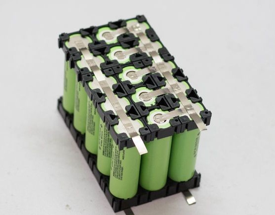
Collects two 3 * 5 cells. Installs, in the cell, the first 5S battery pack with a plus to the top, the next five batteries with a minus up and the last five batteries again a plus up (see photo).
Above sets the second cell.
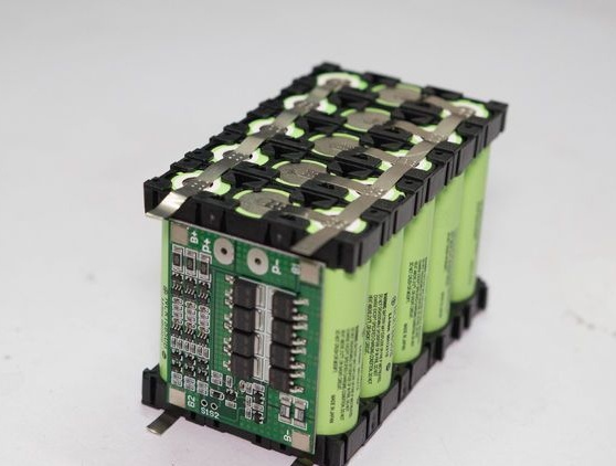
Seventh step: welding
Cuts four nickel strips, for parallel connection, with a margin of 10 mm. Cuts ten strips for serial connection.
Lays a long strip on the + contacts of the first (when it is turned over, it will remain the first) parallel cell 5P. Welds the strip. Welds strips at one end to + third of the cell at the other to - second. Welds a long strip to + third of the cell (over the plates). Flips the block. Welds the plates on the reverse side, given that now we are connecting the third and parallel sections of the first and second sections in parallel (considering that it has been turned over).
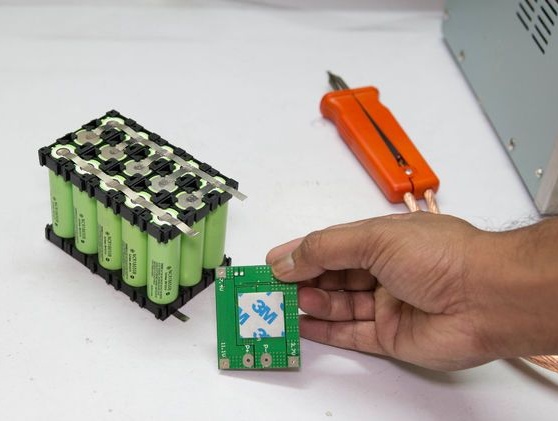
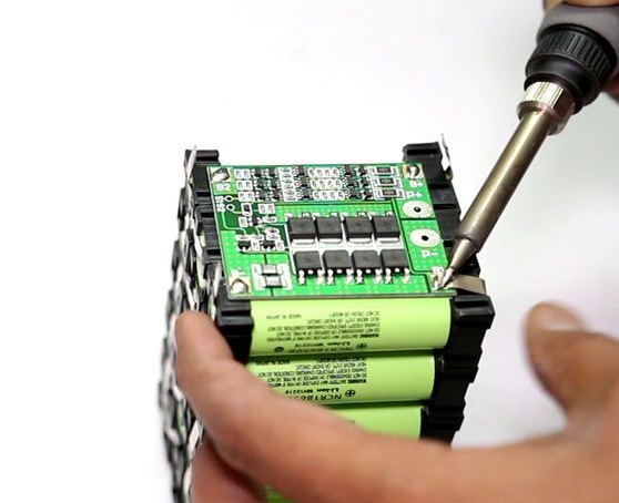
Step Eight: BMS (Battery Management System)
First, let's figure out what BMS is.
BMS (Battery Management System) is electronic a board that is placed on the battery in order to control the process of its charge / discharge, monitor the state of the battery and its elements, control the temperature, the number of charge / discharge cycles, protect the components of the battery. The control and balancing system provides individual control of the voltage and resistance of each battery element, distributes currents between the components of the battery during the charging process, monitors the discharge current, determines the loss of capacity from imbalance, and ensures safe connection / disconnection of the load.
Based on the received data, BMS performs cell charge balancing, protects the battery from short circuit, overcurrent, overcharge, overdischarge (high and excessively low voltage of each cell), overheating and overcooling. The functionality of BMS allows not only to improve the operating mode of batteries, but also to maximize their service life.
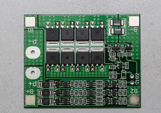
Important parameters of the board are the number of cells in the row, in this case 3S, and the maximum discharge current, in this case 25 A. For this project, the master used board with the following parameters:
Model: HX-3S-FL25A-A
Overvoltage range: 4.25 ~ 4.35 V ± 0.05 V
Discharge Voltage Range: 2.3 ~ 3.0 V ± 0.05 V
Maximum working current: 0 ~ 25 A
Operating Temperature: -40 ℃ ~ + 50 ℃
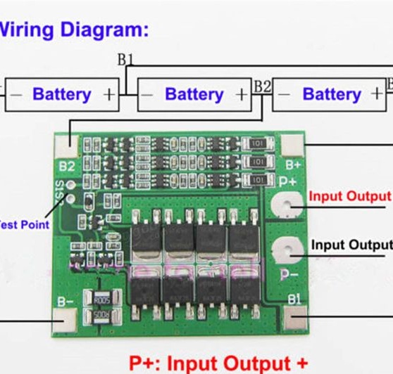
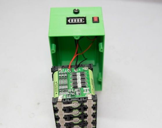
Solder the board to the ends of the battery according to the diagram.

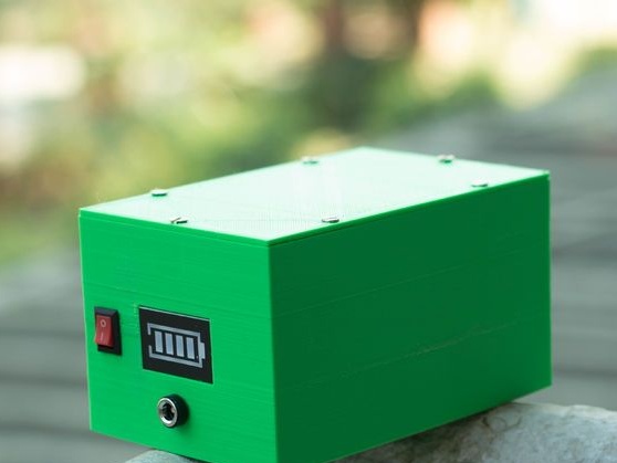
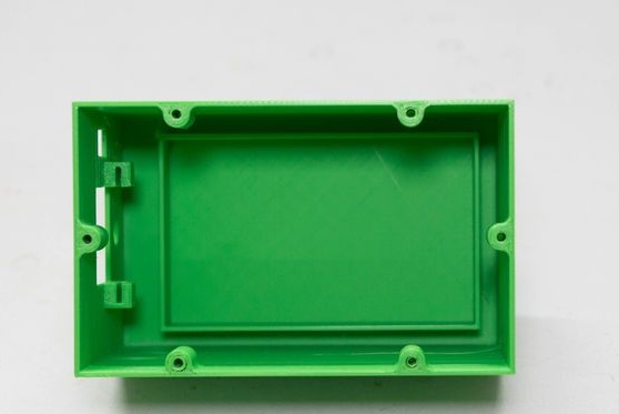
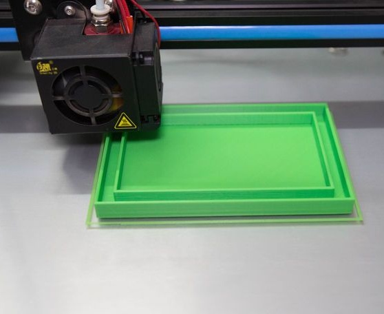
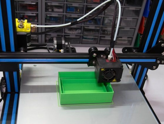
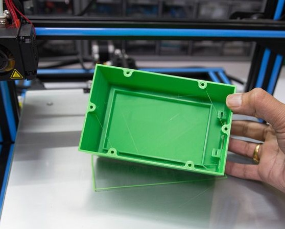
Step Nine: The Case
The body is made by a master on a 3D printer.
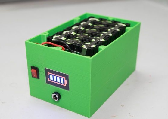
Step Ten: Build
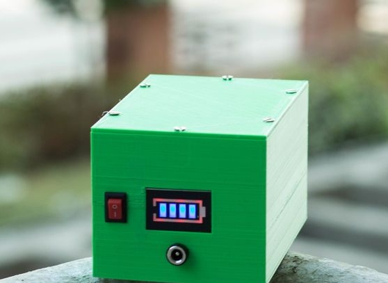
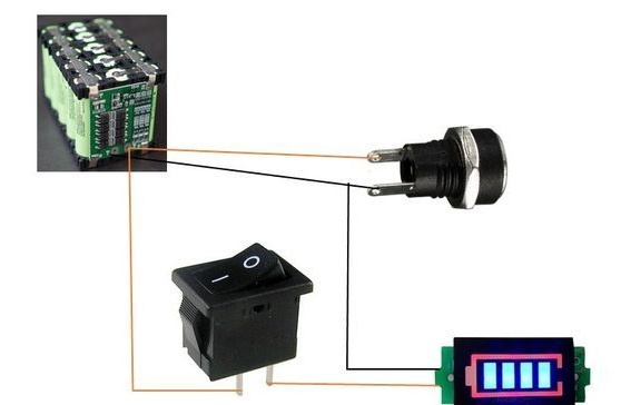
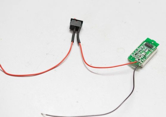
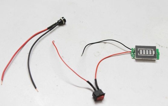
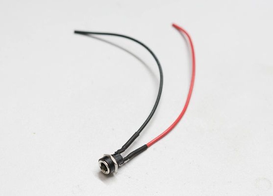
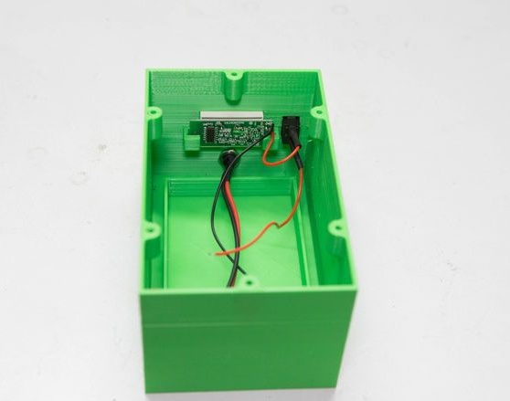
Now you need to install the battery indicator, indicator switch and connector for charging or loading. It mounts everything according to the scheme (black wire to P-, brown to P +) and installs it in the case.
Screws on the lid.
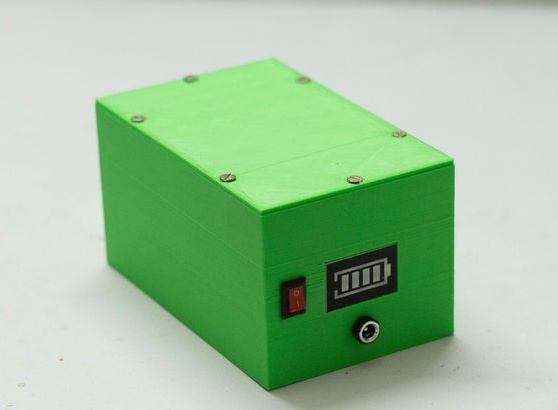
A 12.6 V 2A adapter can be used for charging.
