In radio communications, antennas are given a central place, to ensure its best, radio communications, the antennas should be given the closest attention. In essence, it is the antenna that implements the radio transmission process itself. Indeed, a transmitting antenna, powered by a high-frequency current from a transmitter, converts this current into radio waves and radiates them in the desired direction. The receiving antenna, however, performs the inverse transformation of radio waves into a high-frequency current, while the radio receiver performs further transformations of the received signal.
Radio amateurs, where you always want more power, have a maxim for communication with possibly more distant interesting correspondents - the best amplifier (HF) is an antenna.
To this club by interests, so far I belong somewhat indirectly. There is no amateur radio call sign, but it’s interesting! You can’t work on the transfer, but listen, make an idea, that’s please. Actually, such an activity is called radio surveillance. At the same time, it is quite possible to exchange with a radio amateur whom you heard on the air, receipt cards, of a standard form, on the QSL radio amateur slang. Confirmations of reception are also welcomed by many broadcasting HF stations, sometimes encouraging such activities with small souvenirs with the logo of the radio station - it is important for them to know the conditions for receiving their broadcasts in different parts of the world.
The observer's radio can be quite simple, at least in the beginning. The antenna, the construction is not an example more cumbersome and expensive and the lower the frequency, the more cumbersome and expensive - everything is tied to the wavelength.
The bulkiness of antenna structures is largely due to the fact that at a low height of the suspension, antennas, especially for the low-frequency ranges - 160, 80.40 m, work poorly. So the bulkiness is provided to them by just masts with guy wires, and, of course, tens of lengths, sometimes hundreds of meters. In a word, not particularly tiny things. It would be nice to have for them a separate field near the house. Well, that's how lucky.
So, an asymmetric dipole.
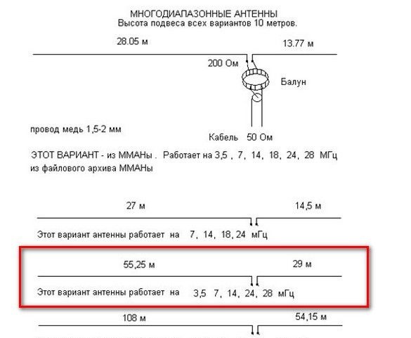
Above, a drawing diagram of several options. MMA, mentioned there, is a program for modeling antennas.
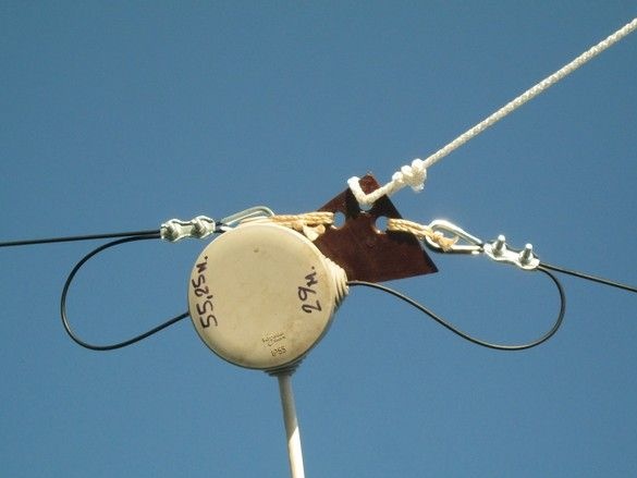
The conditions on the terrain were such that a two-piece version of 55 and 29m fit comfortably. He stopped on it.
A few words about the radiation pattern.
The antenna has 4 petals, “pressed” to the canvas. The higher the frequency, the more they “cling” to the antenna. But truth and gain have more. So on this principle
it is possible to build completely directional antennas, which have a truth, in contrast to the “right” ones, not a particularly high gain. So you need to place this antenna given its daylight.
The antenna on all ranges indicated in the diagram has an SWR (standing wave coefficient, a parameter for the antenna is very important) within the reasonable range for HF.
To coordinate an asymmetric dipole - aka Windom - we need SHTTDL (broadband transformer on long lines). Behind this terrible name lies a relatively simple construction.
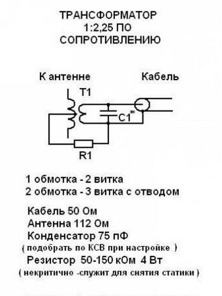
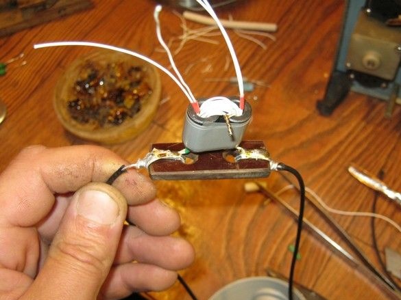
It looks something like this.
So what has been done.
The first thing I decided on strategic issues.
I was convinced of the availability of basic materials, mainly of course, a suitable wire for the antenna sheet in the proper amount.
Decided on the place of suspension and "masts". Recommended suspension height - 10m. My wooden mast, standing on the roof of the woodman, was turned in the spring by freezing snow falling down - I did not wait, as it was not a pity, I had to clean it. It was decided so far to hook one side over the ridge of the roof, while the height will be about 7m. Not much, of course, but cheap and cheerful. It was convenient to hang the other side on a linden standing in front of the house. The height there turned out 13 ... 14m.
What was used.
Instruments.
Soldering iron, of course, with accessories. Power, watts, that way for forty. Instrument for radio installation and small locksmith. Whatever be boring. A powerful electric drill with a long drill-bit on wood was very useful - let the coaxial drop cable pass through the wall. Of course an extension cord to her. Used hot melt adhesive. Work to be done at a height is worth taking care of suitable sturdy stairs. It helps to feel more confident, away from the earth, a safety belt - like the installers on poles. Climbing upstairs, of course, is not very convenient, but you can work already "there", with two hands and without much concern.
Materials
The most important thing is the material for the canvas. I applied a "field vole" - a field telephone wire.
Coaxial cable to reduce how much you need.
Some radio components, a capacitor and resistors according to the scheme. Two identical ferrite tubes from high-pass filters on cables. Thimbles and fasteners for thin wire. A small block (roller) with an ear-mount. Suitable plastic box for transformer. Ceramic insulators for antenna. Kapron rope of suitable thickness.
What was done.
The first step was to measure (seven times) pieces of wire for the canvas. With some margin. Cut off (once).
He took up the manufacture of a transformer in a box.
Picked up ferrite tubes for the magnetic circuit. It is made of two identical ferrite tubes from the filters on the monitor cables. Now, old CRT monitors are simply thrown away and finding the “tails” from them is not particularly difficult. You can ask your friends, for sure, no one gathers dust in the attics or in the garage. Good luck if you have familiar system administrators. In the end, in our time, when switching power supplies are everywhere and there is a serious struggle for electromagnetic compatibility, there can be many filters on the cables where, moreover, such ferrite products are vulgarly sold in stores electronic components.
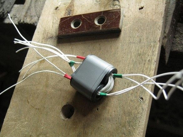
Selected identical tubes are folded in the manner of binoculars and fastened with several layers of adhesive tape. The winding is made of a mounting wire of the maximum possible cross section, such that the entire winding fits in the windows of the magnetic circuit. The first time it didn’t work and I had to act by trial and error, fortunately, there are very few turns. In my case, there was no suitable cross-section at hand and I had to wind two wires at the same time, making sure in the process that they did not overlap.
To obtain a secondary winding - we make two turns with two wires folded together, then pull each end of the secondary winding back (to the back of the tube), we get three turns with a midpoint.
From a piece of rather thick PCB, a central insulator is made. There are special ceramic ones for antennas, of course it is better to use them. Since all laminated plastics are porous and, as a result, very hygroscopic, so that the antenna parameters do not “float”, the insulator should be thoroughly saturated with varnish. Applied oil glyptal, yacht.
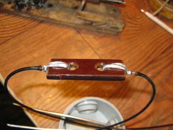
The ends of the wires are cleaned of insulation, several times passed through the holes and well soldered with zinc chloride (soldering acid flux), so that the steel wires also disappear. Places of soldering are very thoroughly washed with water from residual flux. It can be seen that the ends of the wires are pre-threaded into the holes of the box where the transformer will sit, otherwise you will then have to thread all 55 and 29 meters into these holes.
I soldered to the places of cutting the corresponding terminals of the transformer, shortening these conclusions to a minimum. Do not forget before each action, try on the box, so that later everything fits.
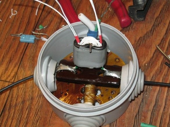
From a piece of PCB from an old circuit board, I sawed a circle at the bottom of the box, in it there were two rows of holes. Through these holes, a coaxial drop cable is fastened with a bandage of thick synthetic threads. The one in the photo is far from the best in this application. This is a television with foamed insulation of the central core, she lived "mono" for screw-on television connectors. But there was a trophy cove. Applied it. A circle and a bandage, thoroughly saturated with varnish and dried. The end of the cable is pre-cut.
The remaining elements are soldered, the resistor is composed of four. Everything is covered with hot-melt adhesive, probably in vain - it turned out to be hard.
Ready-made transformer in the house, with "conclusions".
Between the case, a mount was made to the ridge - there are two boards at the very top. Long strips made of roofing steel, eyelet made of stainless 1.5mm. The ends of the rings are welded. On strips along a row of six holes for self-tapping screws - distribute the load.
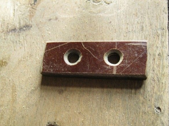
Block prepared.
I didn’t get ceramic antenna “nuts”, I used vulgar rollers from old wiring, fortunately, in old village houses there are still demolitions. Three pieces on each edge - the better the antenna is isolated from the “ground”, the weaker it can receive signals.
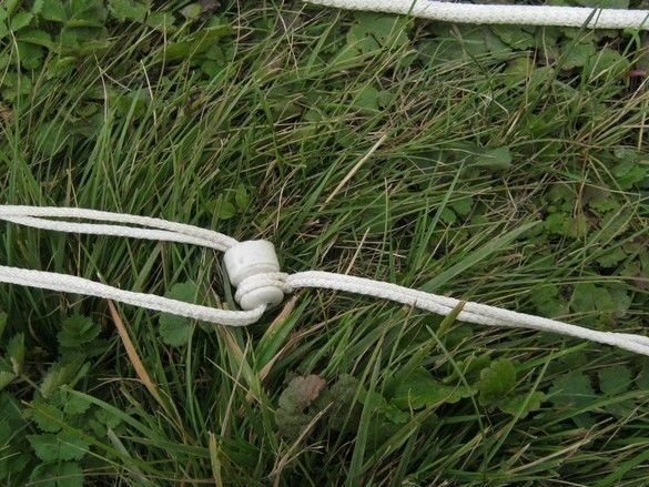
Applied field wire with woven steel veins and withstands stretching well. In addition, it is designed for laying in the open, which is also quite suitable for our case. Radio amateurs quite often make canvases of wire antennas from it and the wire has proved to be quite good. Some experience of its specific application has been accumulated, which first of all says that it is not necessary to bend the wire strongly - insulation bursts in frost, moisture enters the cores and they begin to oxidize, in that place, after a while, the wire breaks.
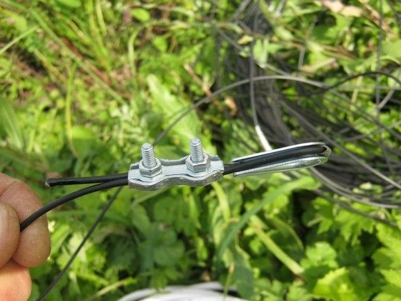
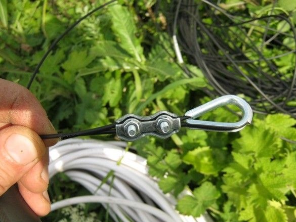
Accordingly, knots on it are not recommended. Standard fasteners for thin cable were used. Clamp and thimble, which allowed to avoid strong "excesses in the field."
The piece of iron for the skate was fixed in place. I barely got it.
In the course of pulling, evaluating the tensile force, I decided, without bringing to sin, to remove the load from the central insulator from the PCB. In order not to redo everything, he got out of the situation like that.
Fortunately, fasteners, mindful of the often folding threads, acquired in double quantity. Useful.
The antenna suspension points have also changed somewhat, for a more convenient location of the drop cable.
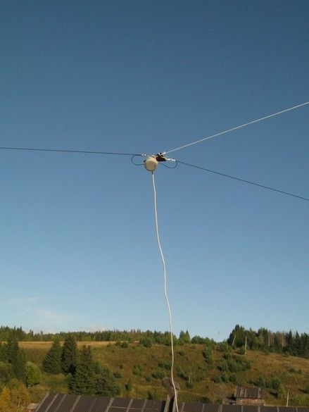
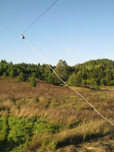
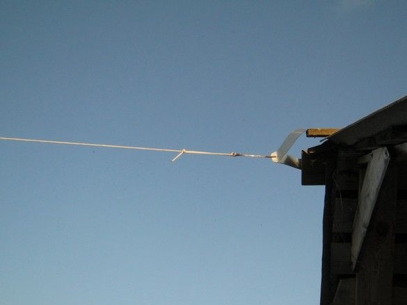
On the top of the tree, with a short rope, a block is fixed to a fixed “ear”. A cord from insulators is thrown through it at the end of the wire of the antenna. The cord goes down. A concrete block suspended by a wire is suspended on it through a carbine for tension. Mobile “fixing” is necessary to compensate for seasonal temperature fluctuations, strong winds, ice freezing.The tension is not up to the string of chimes, without fanaticism.
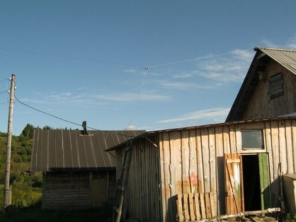
Coaxial drop cable with a slight slack led up to the workshop, mounted on the wall from the outside and in the right place passed inside.