


Tormented in due time with small lead-free parts for printed wiring (SMD) and field-effect transistors soldering them with a large network soldering iron. Then he made a miniature soldering iron from an MLT resistor, but somehow he did not live very long. And then I met a soldering iron from a local Lukey soldering station in a local electric store. I have encountered soldering stations before and the convenience appreciated them. Therefore, the thought came to make the control unit yourself.
What is the difference between a soldering station and a conventional soldering iron, or even a soldering iron with a regulator? The soldering station has feedback. When a sting touches a massive part, the temperature of the sting drops, and the voltage at the output of the thermocouple decreases accordingly. This voltage drop, amplified by an operational amplifier (OA), is analyzed and worked out - the circuit delivers more power to the heater, raising the tip temperature to a set level.
Found a low-voltage soldering iron (24V), quite convenient, in your hand lies like a felt-tip pen, a thin tip, all the iron of the soldering iron is grounded for draining static electricity. The wire is quite soft, in a word, I liked it.
Having rummaged through the vastness, I found many designs, both analog and digital, picked up the most suitable in terms of functionality and containing available elements. The choice fell on the digital soldering station on the ATmega8 microcontroller and a seven-segment LED indicator. Management of five buttons.
The first step was to gut the soldering iron, I wonder how it is made inside. Sfotkal insides, maybe someone will come in handy.
Well, nothing, everything seems to be culturally, at the same time I looked at which wires go - the connector on the tail was a bit liquid, sort of like wee-in-half from mice and keyboards. I replaced it with a DIN 5-pin one, it will be more reliable, the socket, again, is easier to find.
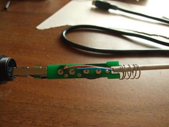
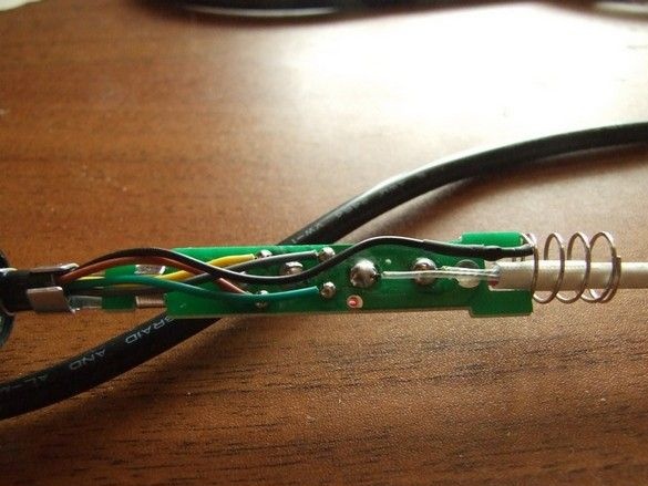
So, here is this handkerchief in the handle, a spring for contacting the "ground" with the other pieces of the soldering iron, including the sting (see about field-effect transistors above).
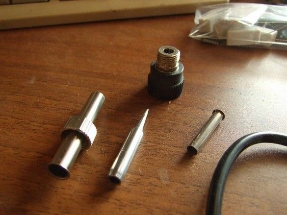
The above glands.
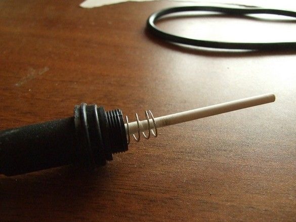
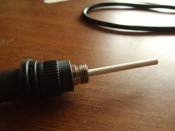
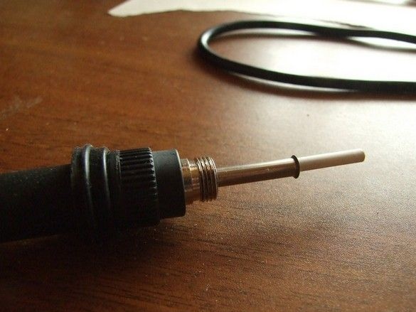
The scarf is put in place, on the outside there is only a contact spring with a ceramic heater, somewhere inside and a thermocouple.
Do it once!
Do two!
Do three.
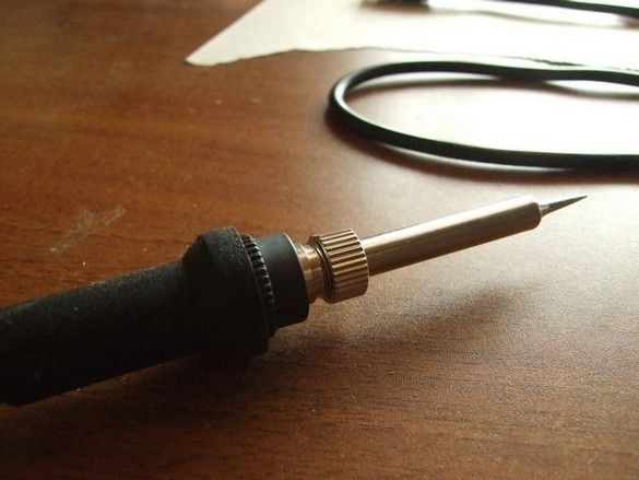
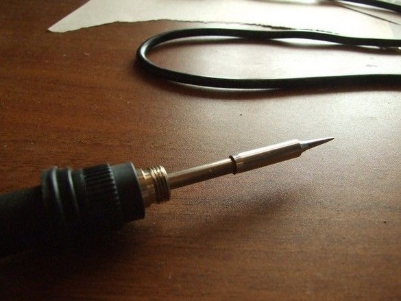
Four. Soldering iron assembly. Applause.
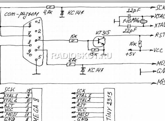
Actually the circuit. Fundamental.
Functionally, the circuit consists of two parts - a control unit and an indication unit.
Where
R1 - 1M
R2 - 1k
R3 - 10k
R4 - 82k
R5 - 47k
R7, R8 - 10k
R indicator -0.5k
C3 - 1000mF / 50v
C2 - 200mF / 10v
C - 0.1mF
Q1 - IRFZ44
IC4 - 7805
A beeper with a built-in generator, connects + to the 14th leg of the controller, - to the minus power.
What can:
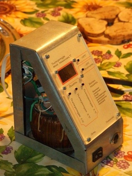
Temperature from 50 to 500g, (heating up to 260g about 30 seconds), two buttons + 10g and -10g of temperature, three memory buttons - long press (until blinking) - memorizing the set temperature, short - setting the temperature from the memory. After power is applied, the circuit sleeps, after pressing the button, the last used temperature setting is turned on. When you first turn on the temperature in the memory 250, 300, 350g. The set temperature blinks on the indicator, then it runs and then the sting temperature lights up to 1 g in real time (after heating it sometimes runs 1-2 g ahead, then it stabilizes and occasionally jumps by + -1 g). 1 hour after the last manipulation of the buttons falls asleep and cools (protection from forgetting, turn off). If the temperature is more than 400g, falls asleep after 10 minutes (for the safety of the sting). The beeper picks when turned on, presses the buttons, writes to memory, reaches the set temperature, warns three times before falling asleep (double beep), and when falling asleep (five-beep).
What is needed.
Materials
In addition to radio elements, there is a mounting wire, a piece of galvanized steel and organic glass, non-thick stainless steel for the stand, neutral silicone sealant, foil material and chemicals for the manufacture of the printed circuit board, and related details.
Instruments.
Soldering iron with accessories, a tool for radio installation and a small metalwork. Scissors for metal. Useful rivets with special pliers for their installation. Something for drilling, including holes on the printed circuit board (~ 0.8 mm), can be contrived with one screwdriver - the scarves are small, there are few holes. Engraver with accessories. You can not do without a computer with special software (PonyProg) for the "firmware" of the microcontroller. Well, if you have access to the printer. In the manufacture of the stand, I used a small welding inverter with accessories, but you can get by with cogs.
The most ergonomic body shape and layout of elements has been worked out in AutoCAD CAD. I had to tinker. I looked at the idea of a case with a sort of pyramid from some expensive bourgeois model of a soldering station. I liked it very much.
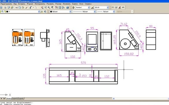
The boards are divorced for the developed case in the Sprint Layout program. Buttons, indicator, directly on the board. Radiator field effect transistor is not required.
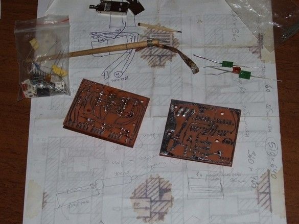
Above, the process of tinning the board tracks and the tool for it is a piece of copper braid wound with a thin wire to the handle. The board after stripping with a fine skin and applying liquid flux, is attached to the table with a clamp, the end of the braid with solder is pressed by a powerful soldering iron to the board and dragged along the paths. They are evenly coated with a thin layer of solder without needles and other defects.
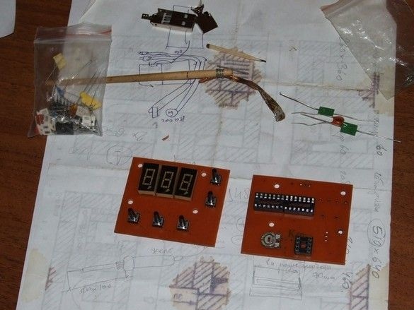
Setting items. Chips are in sockets, since they are cheap and easily accessible. ALS 324 indicators.

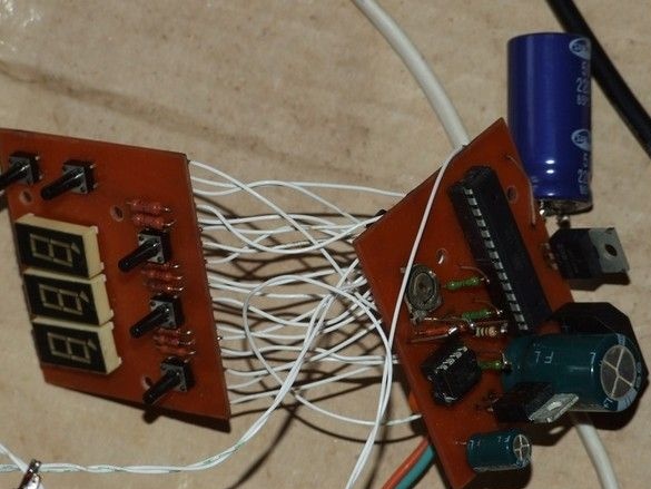
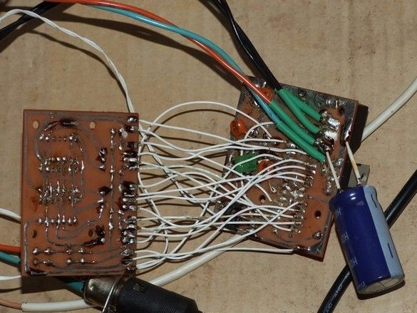
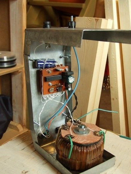
So, well, everything is assembled, the processor is flashed, we are trying to connect to a live thread. From the first time, a bit confused with the indication, after the elimination everything worked as it should. A large capacitor outside the board, appeared during the setup process, it is connected to the rectifier bridge and slightly increases the sagging voltage.
Now, the most difficult thing is to place it in the case. From layouts to tools.
The body is made of galvanized steel roofing. He drew a scan, transferred it to a piece of iron, cut it out with scissors, and bent it. He cut out rectangular windows with a tiny cutting wheel, an engraver.
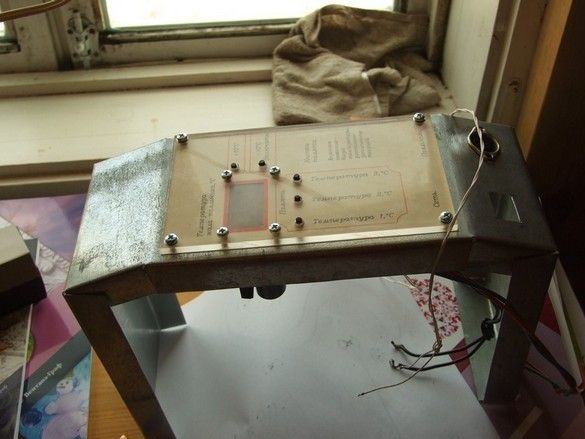
The front panel is a simple, tried-and-tested version of a panel printed on thick paper and plexiglass on top. Light filter on indicators of two layers from a brown disposable eggplant.
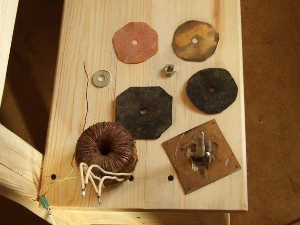
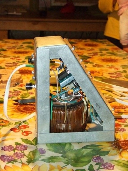
The transformer is quite powerful and accordingly heavy, so to secure it inside the case, it was necessary to build such a mount. A support plate with a welded piece of a threaded rod, a metal washer, rubber gaskets, thread insulation - so that the wires do not distort, a plate with contact petals, so that the solders are not overweight.
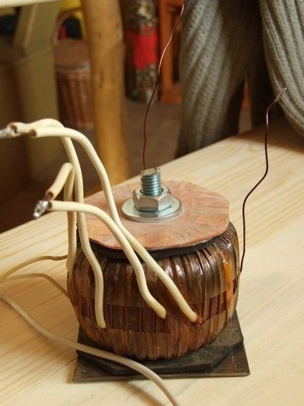
The transformer assembly is mounted in the housing for four corners of the sole with exhaust rivets.
The case is in a combat position, pay attention to a very tight installation - the result of the build-up in AutoCAD.
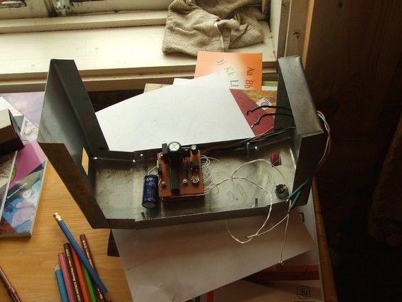
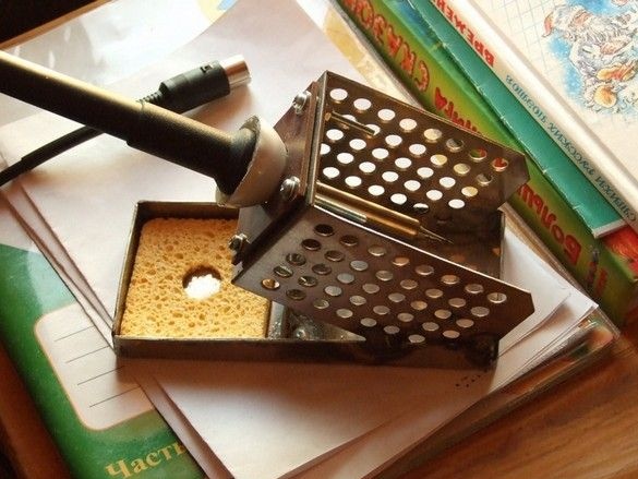
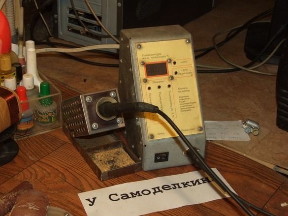
Here, another aspect in the convenience of using a soldering iron is a good stand. Cooked it from a thick sheet of stainless steel, based on the factory. The weight turned out to be quite acceptable, nothing fidgets, does not tip over.
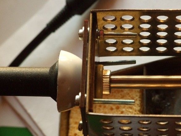
Holder assembly in an intermediate fitting. The cup is made of a cut neck from an empty aluminum can with an inhalip.
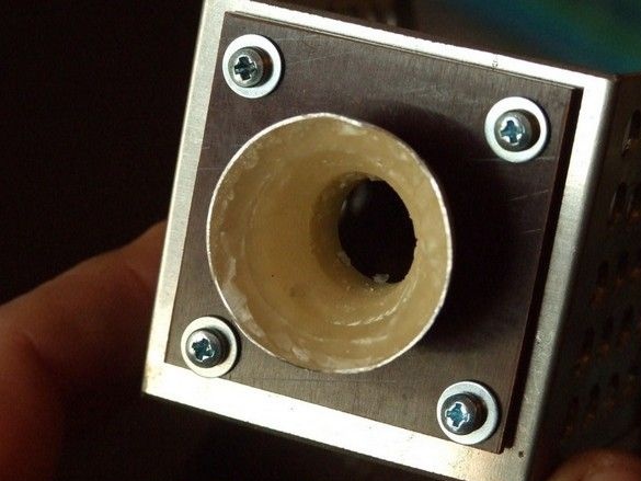
Orthopedic elastic gasket made of neutral (so as not to corrode aluminum) silicone sealant. The molding was carried out by the soldering iron itself. Its corresponding place was tightly wrapped with plastic wrap and pressed into a liquid sealant. The stand in general, and this unit in particular, turned out to be very convenient. The oil seal sits tightly, you can not put it in, but almost throw it in the manner of darts, and without a special clang and rattling. Highly accurate aiming is also not required.
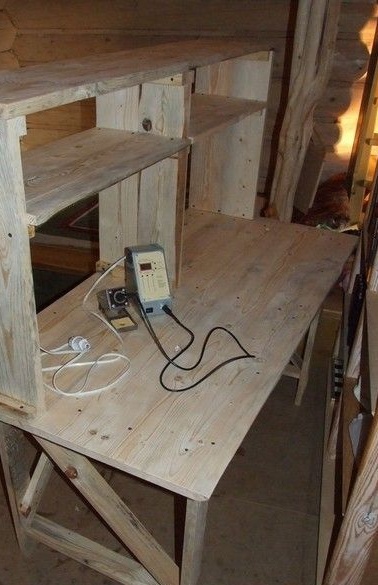
The soldering station assembly, by the way, on a freshly made desktop.
Yes, I had to make a programmer for the controller.
There was no DB-9 for the COM port, I had to make it out of a long one - I waved the "grinder" and come-kuma-admire!
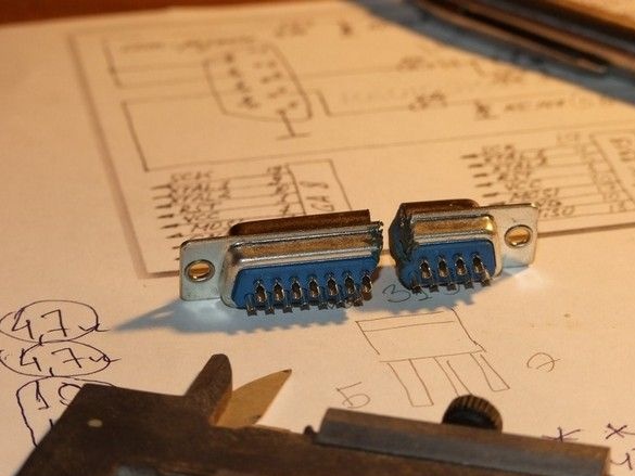
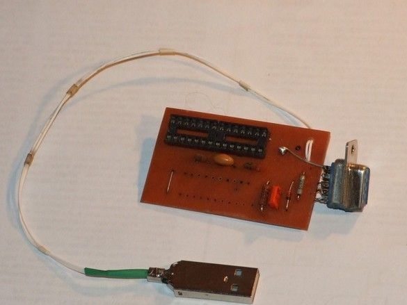
USB is for power.
After more than two years of operation, no significant flaws were found. The indicators only glow dimly under normal working lighting - there were too lazy keys to put transistors. But this is a drawback of the indicators themselves. Without disassembling or dubbing anything, it’s possible to add a blend from above, but it’s not particularly necessary. Three temperatures in memory (standby mode, working mode and for a lead or parts more massive) are set once, then they need only be called up as necessary in "one tyrk".
The authors of the soldering station circuit and controller firmware,