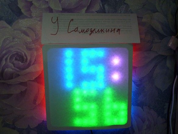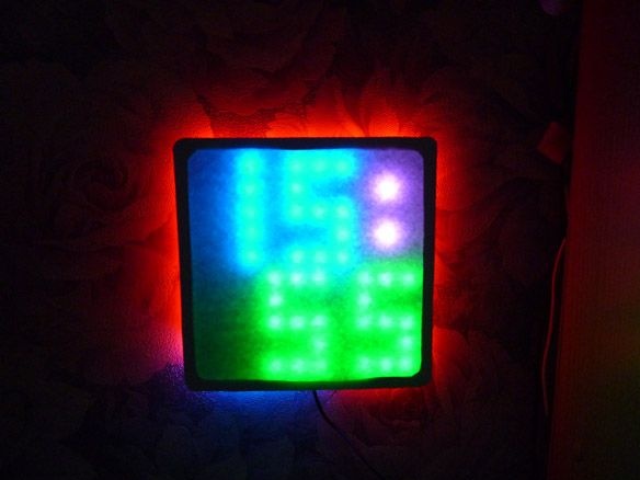
Good afternoon, I want to share another homemade. This time I decided to write instructions for the manufacture of Led matrix. The size is small 10x10 diodes. But according to this instruction, it is possible to make matrixes and large sizes. For beauty added backlight. The basis was taken by WS2812 addressable LEDs mounted on a tape at 60 diodes per meter. We will manage them through Arduino Pro Mini. There are a lot of options for using the matrix. For example, I added a temperature sensor and wrote the clock firmware without RTC.
We will need:
- WS2812 tape with 120 LEDs, 60 pieces per meter
-
- Power supply for 5V 1A
- ds18b20 temperature sensor
- Resistor 4.7 Kom 0.25 W
- chipboard 10 mm thick
- Matte or "Milk" plastic
- Thick cardboard
- electrical tape
- connecting wires
- Circuit board
- Buttons
- Self-tapping screws 19 mm
- soldering iron
- Solder, rosin
- Double sided tape
- USB-TTL
- Drill or screwdriver
- Electric fret saw
- Drills for wood
Step 1 Preparation of Diodes
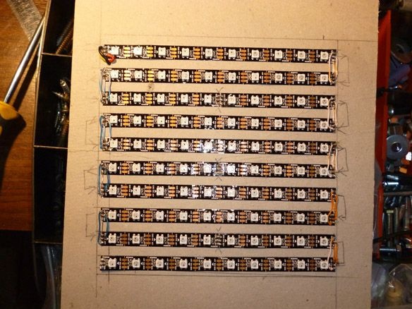
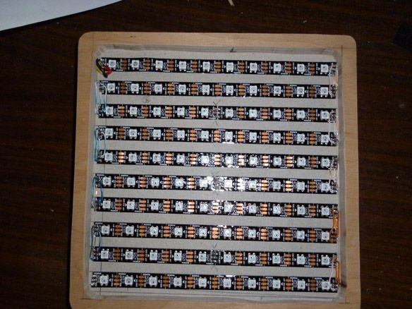
We take a dense cardboard and “lined” it, that is, we draw horizontal lines with a distance between them of 16 mm. We count 100 diodes from our tape. These 100 diodes mode into segments of 10 diodes. The remaining 20 are cut one diode. This must be done carefully and strictly along the cut lines. Let me explain: 10 segments of 10 diodes total 100 are needed for the matrix, the remaining 20 are backlit. Sections of 10 diodes are glued onto the cardboard along the lines. Pay attention to the direction of the control signal for the diodes! The control signal should be supplied in the correct direction, for this purpose the arrow is shown on the tape direction. Glue the first strip from left to right, that is, IN (input) on the tape should be on the left, and OUT (on the right). Thus, the IN (input) of the first strip should be in the upper left corner! Glue the next strip on the contrary, from the right - to the left. The third again from left to right. Etc. When following the direction of the control signal, we should get a zigzag line, starting from the upper left corner. The main thing is not to confuse anything.
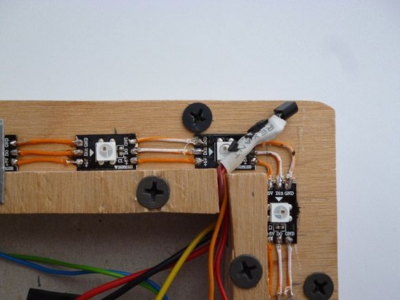
Between the first and second strip, closer to the beginning, makes a hole for the wires. Solder the wires to the first strip, preferably multi-colored, so as not to mix up. We pass them through the hole made. Next, solder our stripes with short wires. + 5 from the first cavity to +5 the second. GND to GND. From the OUT of the first strip to IN of the second strip, from the OUT of the second strip to IN of the third, and so on. The result should be the following:
Step 2 Making the case.
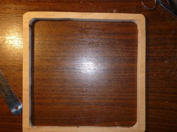
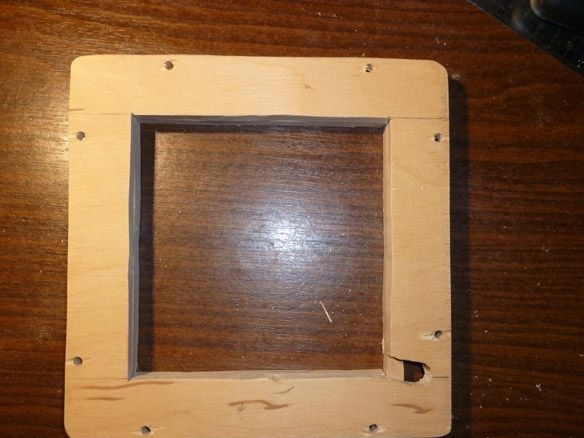
The case consists of three parts. First, you need to cut the frame from chipboard 10 mm thick. It is best to cut with a jigsaw, but in the absence it can be taken manually. The side of the outer square is 190 mm.Internal - 170 mm. For beauty, it is better to round the corners. Thus, a frame with a size of 190 x 190 mm and a wall thickness of 10 mm should be obtained. After cutting, we clean with fine sandpaper.
We proceed to the manufacture of the second part. We attach our frame to the chipboard sheet and draw a pencil around the outer edge. We remove the frame. We retreat 30 mm on each side into the inside of the square and draw an inner square. You should get another frame measuring 190 x 190, but with a side thickness of 30 mm. At a distance of 5 mm from the outer edge of this frame, and at an equal distance from each other, we make holes with a diameter of 3 mm. 2 holes on each side. They are needed for screws. You also need to decide where the top will be, and in the upper left corner of the inner square, make a slot for the wires.
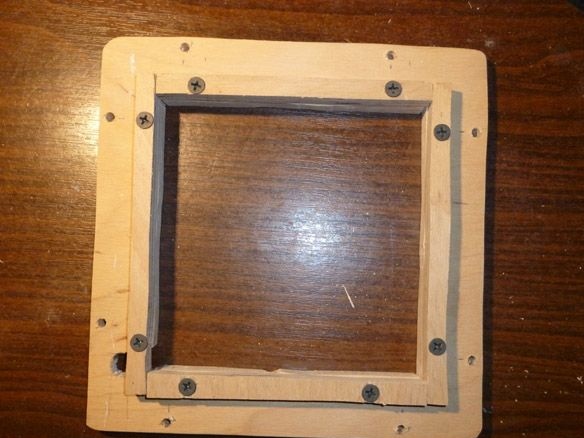
On the reverse side of the second frame, along the perimeter of the inner side, it is necessary to screw segments from the same chipboard 10 mm thick. The result should look like this:
Go to the assembly. We put the second frame on the table. Top, diodes up, put a cardboard box with diodes. And we cover it all with the first frame. Place the cardboard between the frames so that the diodes run parallel to the sides of the frame and at an equal distance from the edges. We turn it all over, very carefully so as not to knock down the diodes, and twist it all together. After that, we cut off the excess cardboard.
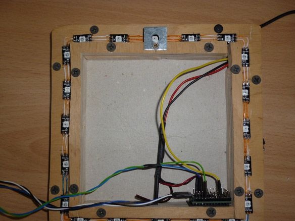
Go to the backlight. On the side of the diodes, between the penultimate and last strip, closer to the left edge, you need to drill a hole for the wires. Solder the wires to the end of the last strip and thread these wires through the hole. The remaining and cut one at a time 20 diodes must be glued on the back side, at an equal distance from each other. 5 pieces on each side. The direction of the control signal is the hourly hand starting from the lower right corner. We solder them as well as the matrix. Derived wires from the end of the matrix are soldered to the first diode. + 5 from the first diode to +5 of the second. GND to GND. From the OUT of the first diode to IN of the second, from OUT of the second to IN of the third, and so on.
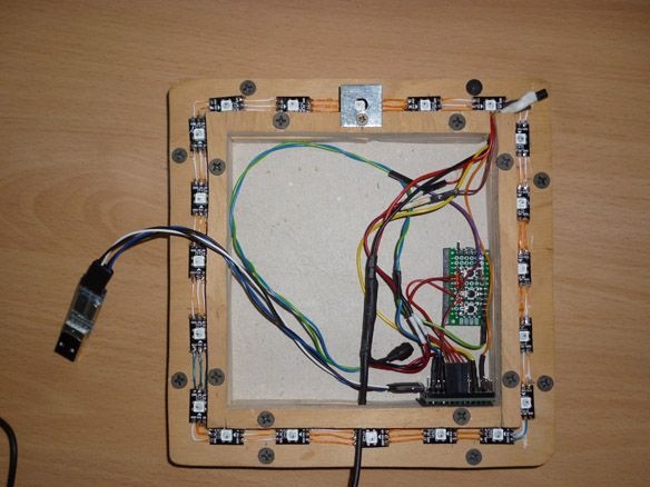
We place our Arduino Pro Mini inside the rear frame, behind the matrix. For power use a stabilized 5 volt power supply. With a current strength of at least 1 Ampere. The diodes are quite voracious and if you plan to turn them on all at once and for a long time, the power supply is needed more powerful, I recommend 1.5 - 2 amperes. We connect all this together from +5 power supply to +5 Arduino and +5 WS2812. -5 power supply with GND Arduino and GND WS2812. The control wire from IN WS2812 is connected to the “pin 6” Arduino.
The diodes are very bright, and they do not look very aesthetically pleasing. Therefore, it is necessary to manufacture and install a diffuser. Matte plastic is best suited for this, or as it is called "milk". It is necessary to attach the matrix to the plastic and circle with a pencil. Then cut and fasten to double-sided tape on the front frame. It is not always possible to find such plastic quickly, but I really want to start the product. In this case, you can use white cardboard or landscape paper instead of plastic.

By the same principle, it is possible to make a matrix of large sizes. It is only necessary to recount the dimensions of the case.
Step 3 Connect the temperature sensor.
It's just that this watch is not interesting, so add a temperature sensor to it. To measure the temperature, we will use the integrated sensor DS18B20. It has a high measurement accuracy, the error is not more than 0.5 ° C. Already from the factory, the sensor is calibrated and no additional settings are required. Wide temperature measurement range -55 ... + 125 ° C. It can be used in any room. If on the street, then you need to take care of protection from moisture. There are two modes of operation: with an external power source and “spurious power”. I recommend using with external power.
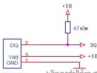
Several sensors can be included on one communication line. But for us, one is enough. +5 we take from the power supply. GND to -5. Wire from pin “DQ” ds18b20 to “pin 9” Arduino.Remember to put a pull-up resistor between “DQ” and +5 at 4.7 kOhm. In my opinion, it is most convenient to do this on the sensor itself. We display it in the upper right corner:
Step 4 Preparing a board with buttons.
In this case, we use the matrix as a clock. The time can be set using the serial port by connecting the Arduino to the computer. This is not always convenient. Therefore, we will manufacture a board with three buttons to set the time. In addition to this, the matrix can be used for other purposes, just write another sketch. Then the buttons can be used for other purposes.
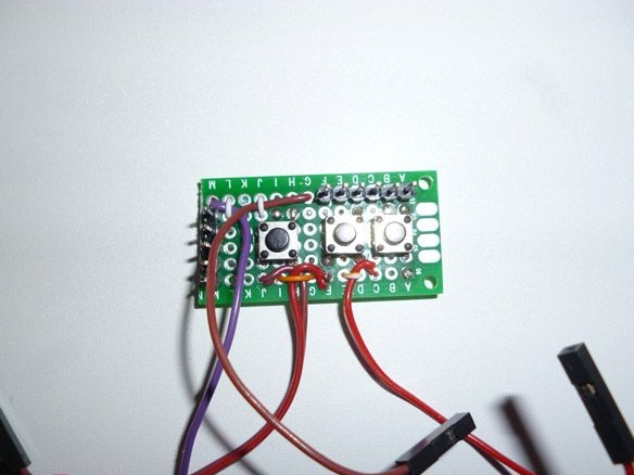
We connect them as follows: connect the wire common to all three buttons to the “GND” Arduino. The first button, it serves to enter the time setting mode and switch over time and date, connect to "Pin 2". The second, the button for increasing the value, is to "Pin 3", and the third, the button for decreasing the value, is to "Pin 4". We attach the buttons to the double-sided tape behind the matrix:
Step 5 Firmware.
As I said, the matrix can be used for different purposes. I have currently written a sketch for watches only. In the subsequent lay out and other sketches. For writing and filling I use Arduino IDE 1.8.5. You can control the matrix in several ways. Control each diode individually or as a single matrix. In my sketch I use the first option. To do this, you need a library from Adafruit called NeoPixel-master:
To work with diodes as with the matrix matrix Adafruit_NeoMatrix-master and Adafruit-GFX-Library-master:
A temperature sensor needs the OneWire library.
To edit and fill the sketch, you must first install the Arduino IDE from the official website of Arduino.cc, and then all these libraries. It is necessary to unzip these archives and place the unpacked files in the “libraries” folder located in the folder with the Arduino IDE installed. It is also possible to install libraries directly in the Arduino IDE. Without unpacking the downloaded archives, in the Arduino IDE, select the Sketch - Connect Library menu. At the top of the drop-down list, select "Add .Zip Library". In the dialog that appears, select the library that you want to add. After all the manipulations, you must restart the Arduino IDE.
The temperature sensor has a unique address for each device - a 64-bit code. Finding this code is a demanding task. Therefore, you must first connect the sensor to the Arduino, fill in the sketch located in the File - Examples - Dallas Temperature - OneWireSearch menu. Next, run Tools - Port Monitor. Arduino should find your sensor and write its address. We copy or simply write down the address of your sensor. Open the sketch Ard_Tic_Tak_WS2812_Matrix_10x10_Serial_Knopki_Term, look for the line:
byte addr [8] = {0x28, 0xFF, 0xDD, 0x14, 0xB4, 0x16, 0x5, 0x97}; // address of my sensor We write down the address of your sensor between braces, replacing the address of my sensor.
This watch does not use the RTC module. Therefore, if they are in a hurry or behind, you should change the value in the line:
if (micros () - prevmicros & gt; 494000) {// change to another for adjustment was 500,000It is necessary to determine this number empirically. If your watch is in a hurry, you should increase this number; if I am behind, decrease it.
Fill the sketch.
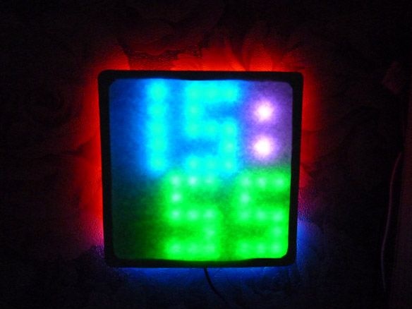
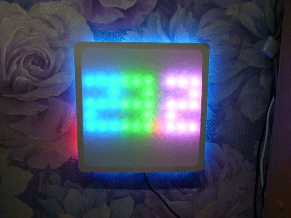
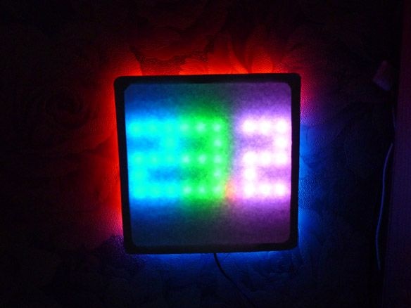
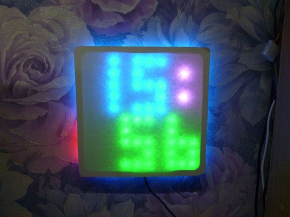
I apologize, but I did not succeed in taking a photo with the diodes turned on. I tried with and without lights. But I assure you live they look much better.