

Gunshot weapons with silicon locks was the main weapon option from the 18th to the middle of the 19th century. The regiments of Rumyantsev and Suvorov fought with him, the United States sought independence, and Napoleon plagued Europe. Recent cases of its use have been noted in the First World War in the Balkans. At the same time there was a period of romantic duels on pistols. Their classic designs had silicon locks, which saved many lives. The time between pulling the trigger and the shot was on the order of a second and not everyone had sufficient hardness of hand and spirit to keep the line of sight. Although, the abundance of contemporaries' mention of flashes of gunpowder in time on a seed shelf, allowing to raise a horse on its hind legs or rushing to the ground to escape an instant before a shot, was rather a consequence of the silence of those who did not succeed.
The device proposed here is also useful for reconstructing a personal story. Many only need a strong associative key to feelings from past lives. Fatal moments in this sense are beyond competition.
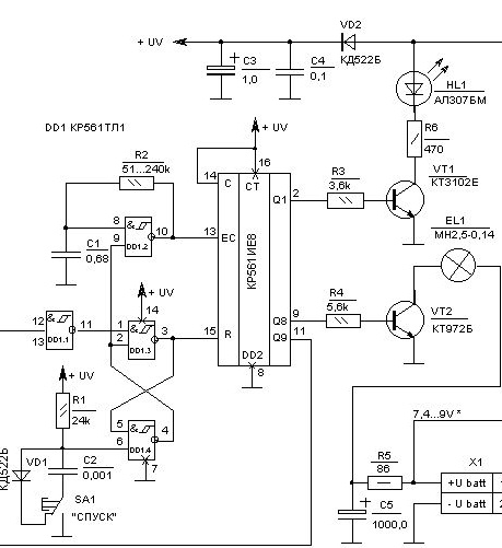
Scheme
Work
Control signals are generated at the outputs of the decimal counter with decoding DD2 type KR561IE8. The clock generator is assembled on one logical element DD1.2 "2I-NOT" with inputs on Schmidt triggers from the composition of the KR561TL1 chip. The parameters of the pulses formed by him are set by the RC chain C1, R1. In the initial state, it is inhibited by a signal of a low logic level at the input (terminal 9). This control signal comes from a trigger formed by elements DD1.3 and DD1.4. From the same trigger, the signal to the reset input R (pin 15 DD2) of the counter keeps it in its initial state.
When you press the trigger of the shooter, the SAKUS button SA1 connects to the input (terminal 6) of the logic element DD1.4 a capacitor C2 previously discharged through the diode VD1. Until it is charged to level 2/3 of the UV - threshold for switching on the Schmidt circuit, the input will have a signal of log.0, which will transfer the trigger to a state that allows the circuit to work. Even the appearance on pin 6 log. 1, when the capacitor is charged, will not change the state of the trigger. The generator is now fed a high level permitting work, and the counter is unlocked.
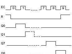
When applying DD2 pulses to the counting input (terminal 13) along the edge of the slice, pulses of positive polarity will appear at the outputs of the microcircuit. At the second step, the pulse appears at the output of Q1 (pin 2) and opens the key on the transistor VT1.In this case, the HL1 LED will light up for the duration of the pulse. It simulates a flash of gunpowder on a seed shelf.
Upon the arrival of the 9th pulse from the generator at the output of Q8, a high potential will appear and the current through R4 to the base VT2 will open it, which will create a condition for the discharge of the storage capacitor C5 through the filament of the lamp EL1. It will give a flash of light, which is formed by optics into a beam.
With the removal of the high potential from Q8, the transistor VT1 closes and the charge C5 from the battery begins. The charge current is limited by the presence of resistor R5 in the circuit. The presence of R5, which translates expensive energy into heat, is a lesser evil, regarding the premature failure of the battery under the influence of transcendent current pulses. It should be noted that there are galvanic cells and batteries (expensive!) Specially designed for strong and pulsed currents, for example, from those recommended for cameras, flash units, radio stations. If you mean working with a battery with strictly known parameters, which usually happens when using built-in batteries, then it is reasonable to put R5 exactly under the permissible current without protection from nonsense acquired on the occasion. For this circuit, consider:
R5 = (Ubatt - 1.5) / Ibatt max.The arrival of the tenth pulse counter initiates the completion of the circuit. The positive signal log.1 from the output of Q9 (pin 11 DD2) is inverted to DD1.1 and the log. 0 sets trigger DD1.3-DD1.4 to the initial standby state when the generator and the counter are blocked.
Although the device is powered by a galvanic battery in standby mode, the consumption of inhibited CMOS circuits and closed transistor switches is so minimal that you can do without the on / off switch. For toys, this is a big plus.
Logic (+ UV) is powered separately from the keys. It comes from C3 + C4, recharged through the VD2 diode by the current from Ubatt. The large-capacity C3 stores energy, and the inertialess C4 compensates for the inertia of the electrolytic C3 when switching logic. The most severe disturbance in power is when the voltage drops across C5, discharged to EL1. The VD2 diode at the same time protects against discharge C3 + C4, and the galvanic battery is protected by a current-limiting R5.
Pay
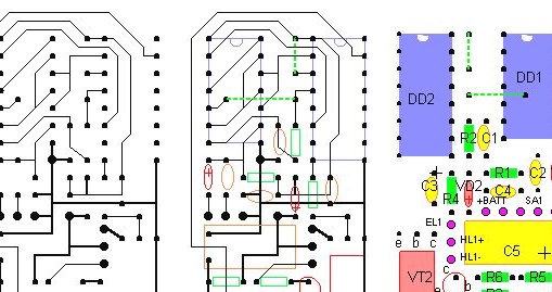
Printed circuit board. The pitch of the holes for the terminals of the 1.25 or 1.23 mm microchips, depending on whether they are domestic or imported. LED HL1, switch SA1, lamp EL1 and galvanic battery GB are located outside the board.
Replacements
DD1 - a set of logic elements 4 X 2 AND NOT with inputs on Schmidt triggers.
In this position, any clones of the CD4093 chip are suitable.
DD2 - decimal counter with decryption.
Any clones of CD4017 are suitable.
C3, C5 - capacitors.
When using polar capacitors, the operating voltage for which they are designed must not be lower than the maximum for a fresh battery. When using non-polar C3, the capacitor C4 is superfluous.
With a constantly connected battery, the C5 is the most problematic element. In fact, it alone determines the battery life with its leakage current. I recommend measuring this parameter to select the most economical sample.
VD1, VD2 - diodes.
Replaceable for any low-power diodes.
SA1 - switch.
By function, this is a trigger, to which specific requirements are imposed on smoothness, pressure and stroke length. You can look for a microswitch with such characteristics, but it is easier to get them separately, leaving him only the switching function. Moreover, in the duel pistols, the bulk of which was with a silicon lock, there was also a special regime of hard descent, which protected inexperienced, worried shooters from a premature shot.
In many pistol-like devices, such as high-voltage powder paint sprayers, the switching element is a three-pin switching reed switch, which triggers when a small magnet is pulled into the trigger. This design has a very large response resource.
Hl1 - Light-emitting diode.
It imitates an outbreak of gunpowder on a shelf and, apparently, should be shades of red or orange. To select the brightness of the flash, vary the current-sensing resistor R6. The low duty cycle of the pulses allows you to choose a current up to ten times the nominal. The type of LED and its design is any.
EL1 - miniature incandescent lamp.
The indicated type of transistor VT2 allows you to turn on the lamp with a rated current of up to 300 mA. This is more than enough to choose any of the domestic miniature general-purpose lamps.
Evg. Fistula