
In this article, Konstantin, How-todo workshop, will show in detail how to make a simple dosimeter on Arduino nano and SBM20 (STS-5).
The dosimeter, by its principle of operation, is a very simple device.
To build it we need:
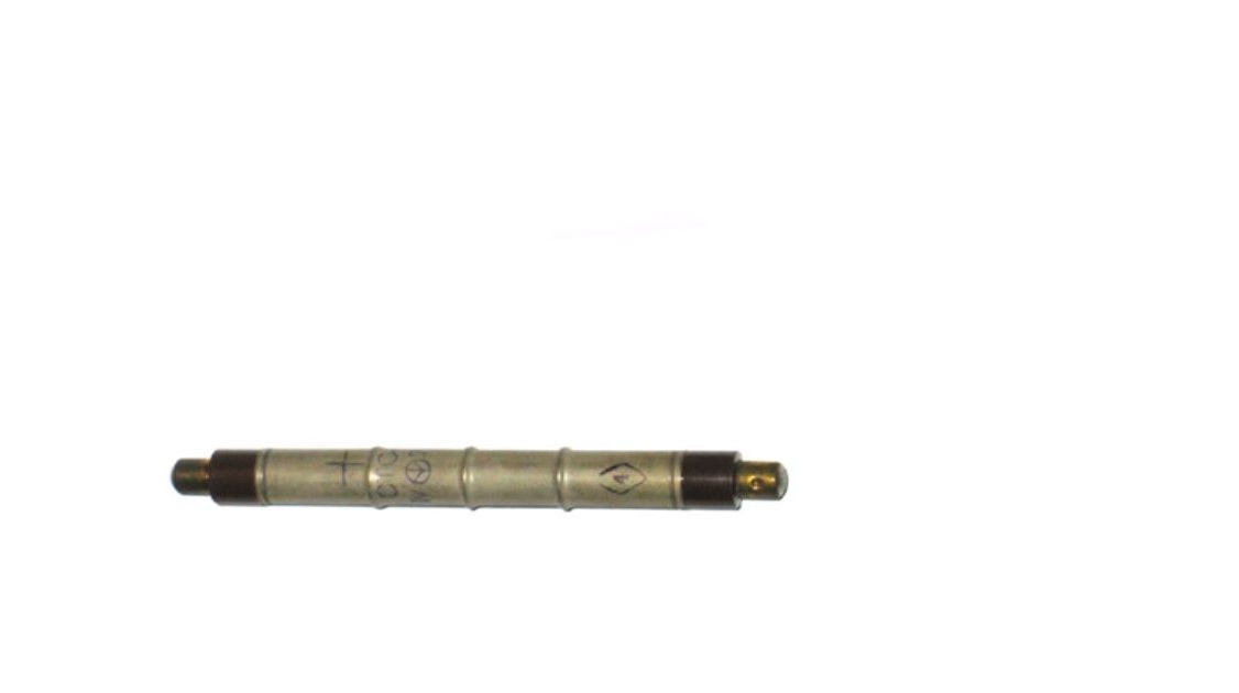
Actually, a device for recording charged particles, for which we will use a Geiger tube.
High voltage power supply for it, with an output voltage of about 400 V.
Indication device, sound or light, which will report breakdowns in the handset.
In the simplest case, you can use a speaker as an indicator.
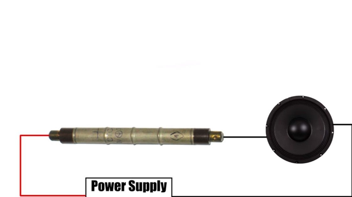
A charged particle striking the counter wall knocks electrons out of it.
And in the gas that the tube is filled with, a breakdown occurs. For a very short time, the speaker receives power through the handset and it clicks. Of course, everyone will agree that clicks are not the best way to get information.
Clicks, of course, will be able to warn of an increase in the background, but counting them with a stopwatch to get accurate readings is simply an outdated method.
We will use new technologies and fasten them to the handset electronic brain with a display.
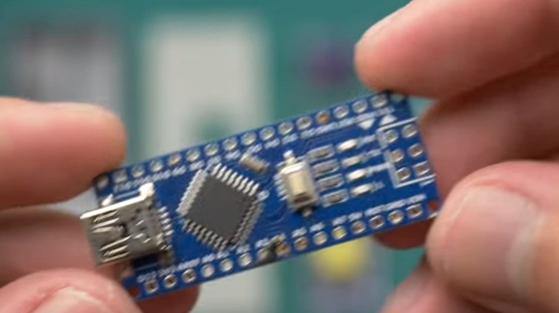
Let's move on to practice. Electronics is presented in the form of an Arduino nano board.
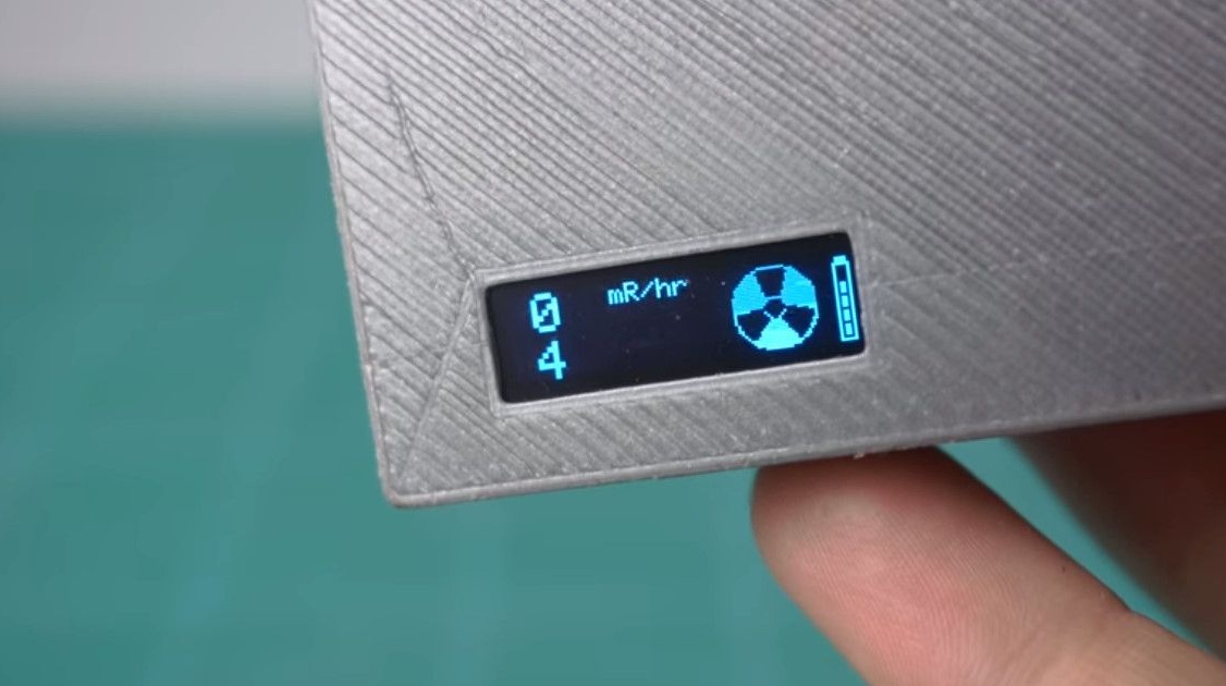
The program is very simple, it counts the number of tube breakdowns for a certain time interval, and displays the received data on the screen.
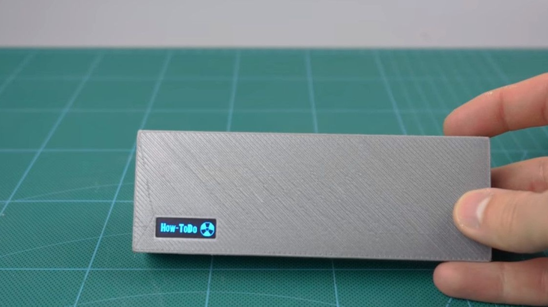
Also, at the time of breakdown, a radiation symbol is displayed, as well as a battery indicator.
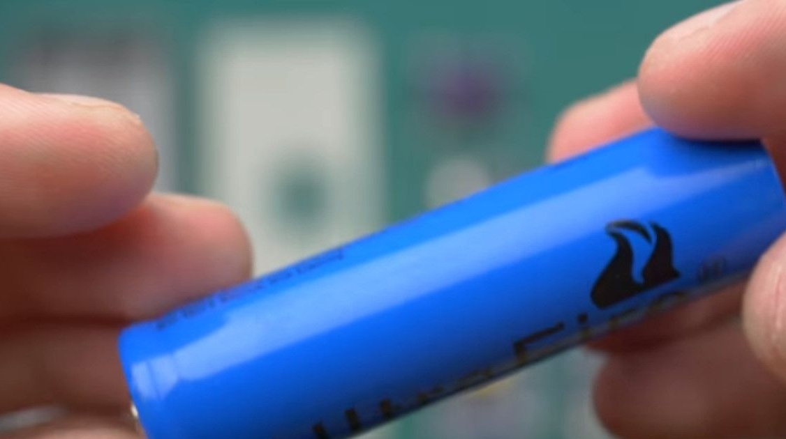
The device’s power source is a 18650 battery.
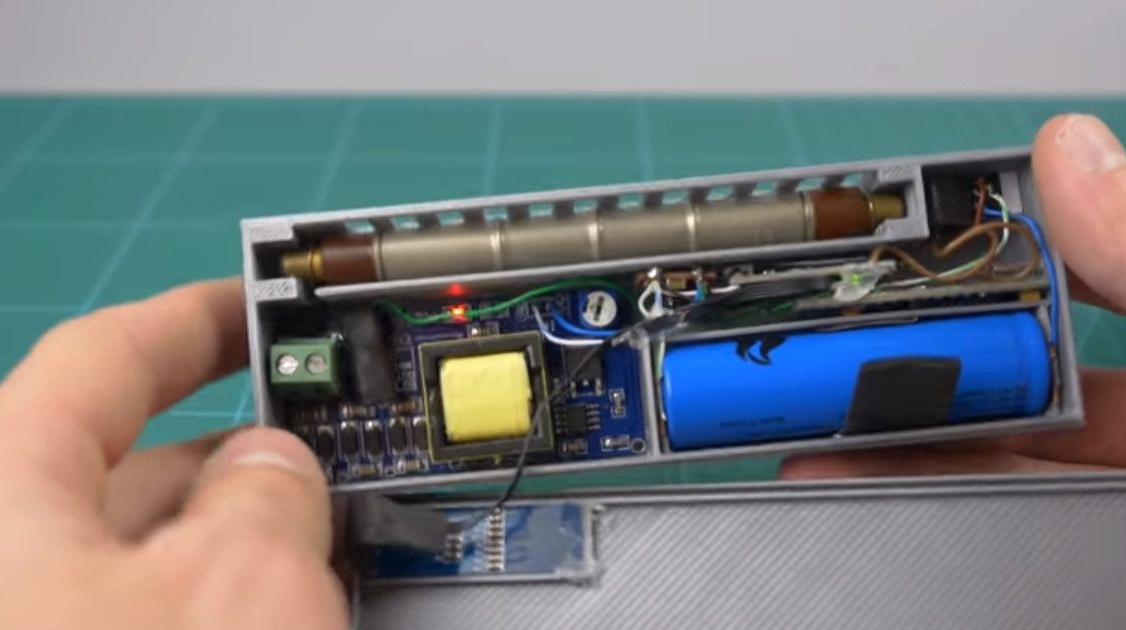
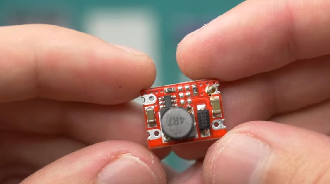
Due to the fact that the arduino board is powered by 5V, a module with a converter is installed.
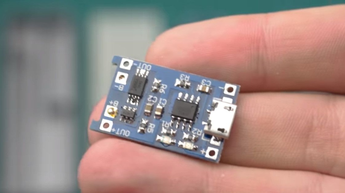
A battery management board is also installed to make the device fully autonomous.
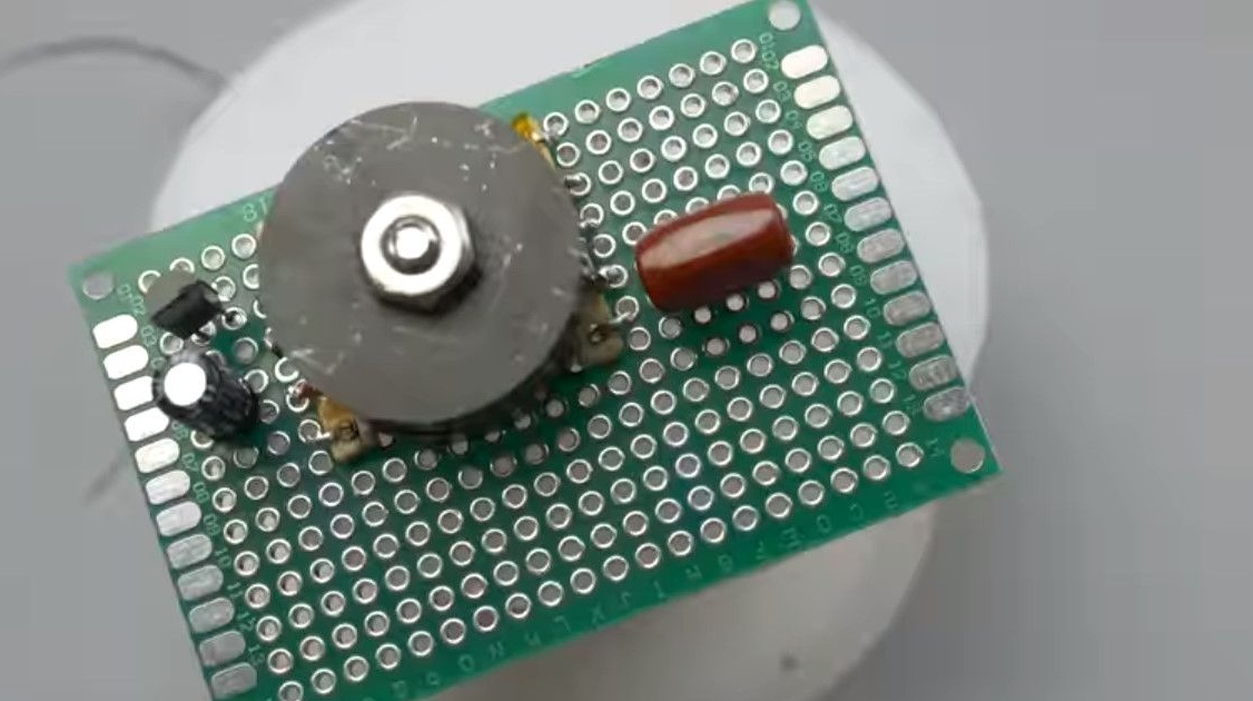
Difficulties began when the author began to solve the problem with a high-voltage converter.
He originally made it himself. A transformer was wound on a ferrite core, about 600 turns of the secondary.

The signal came from the integrated PWM in the Arduino. Through a transistor, this works quite fine.
The author, however, I wanted to make the design accessible for repetition to anyone, even a beginner.
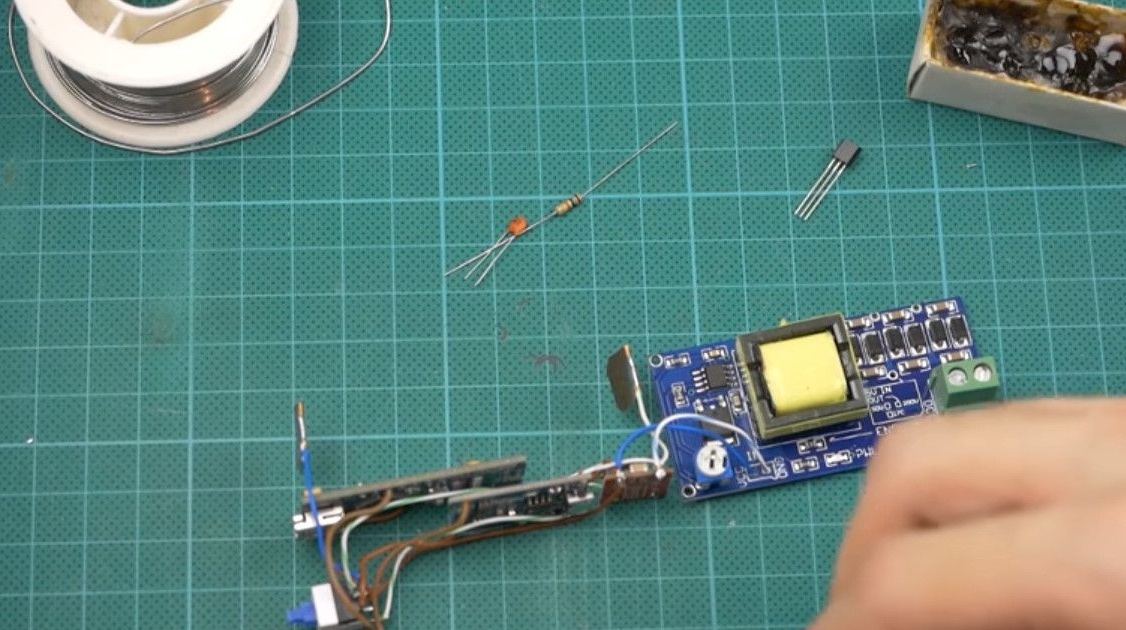
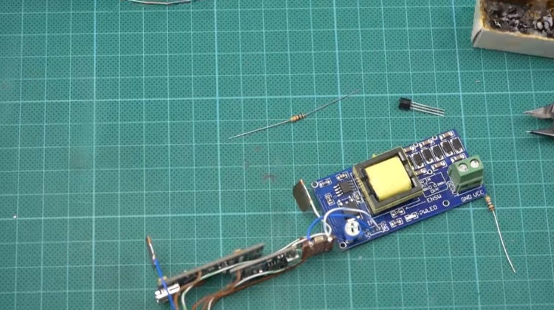
After some time, Konstantin found high-voltage converters on aliexpress.
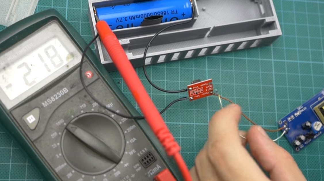
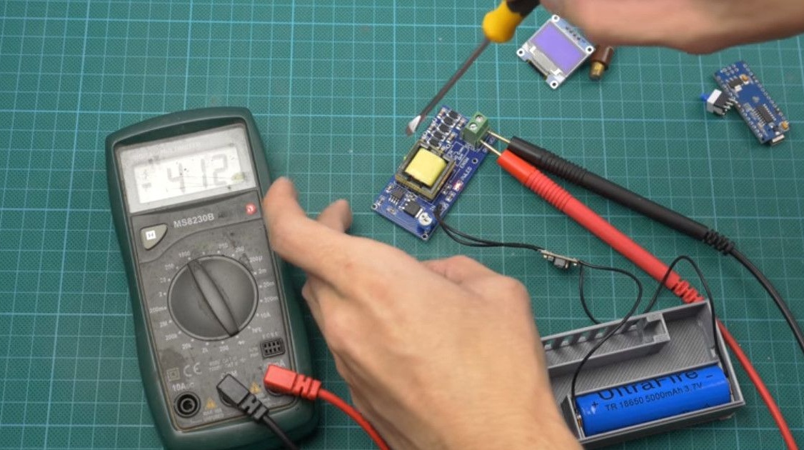
Let's start testing the purchase version. He gave out a maximum of 300 Volts, with already declared 620.
Having ordered another, it turned out to be of different sizes, despite the fact that the previous ones were indicated in the description.
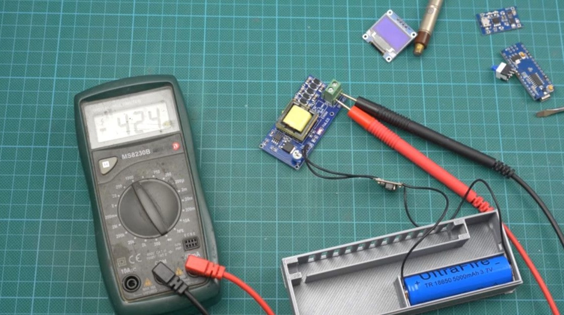
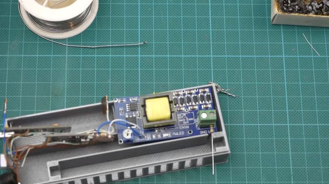
The last converter was still able to produce the required voltage of 400 V, the maximum was 450, with the manufacturer's declared 1200V.
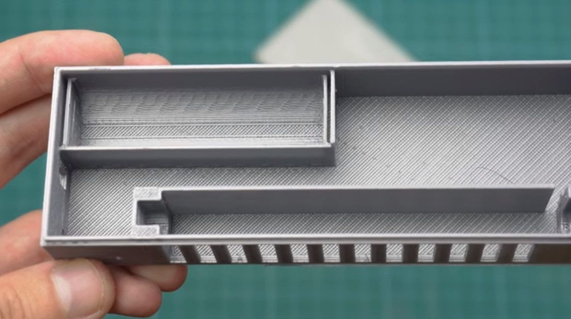
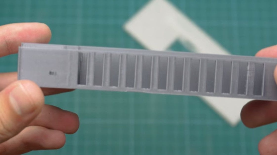
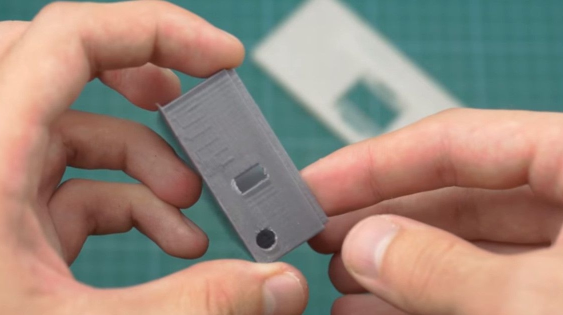
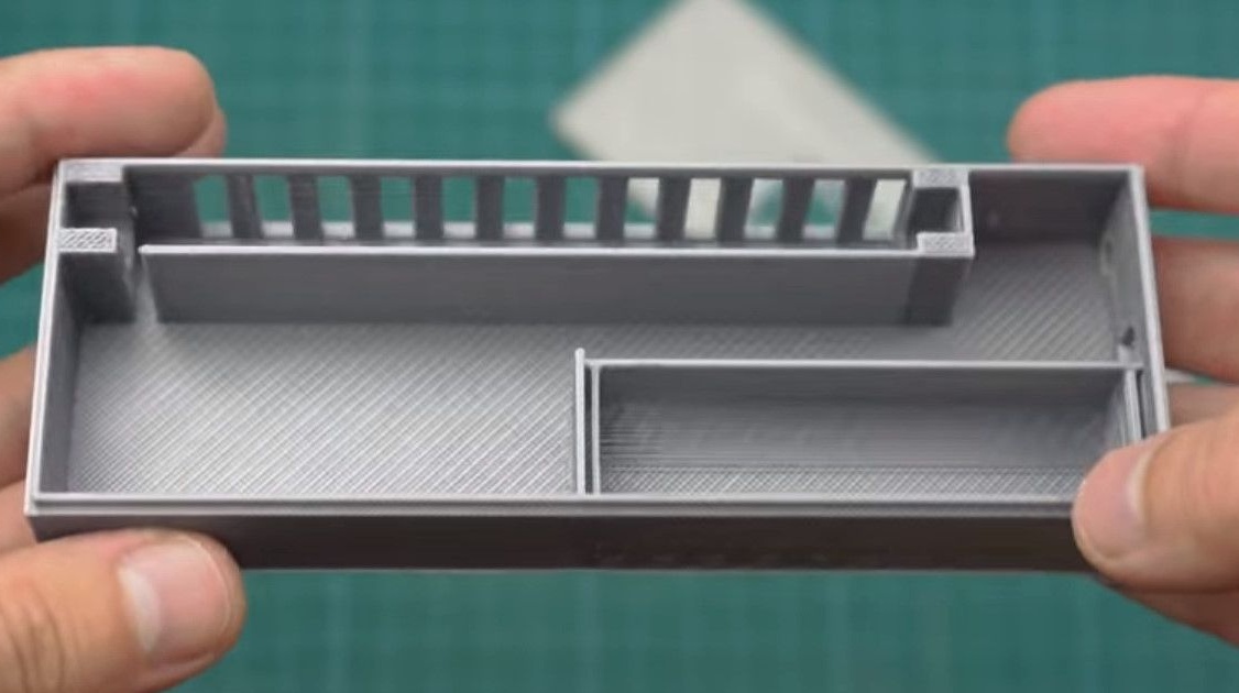
We remodel the case for a different size of the converter.
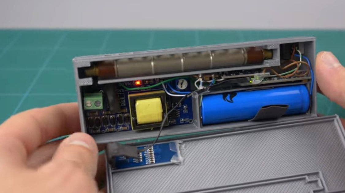
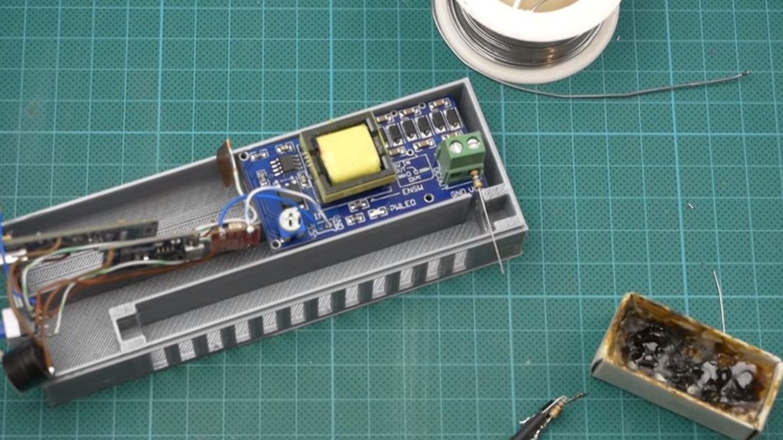
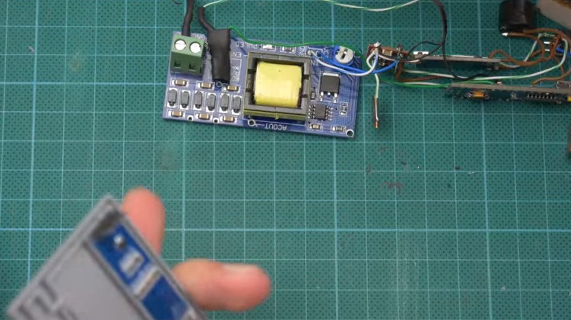
In the end, we get a design that almost entirely consists of modules.
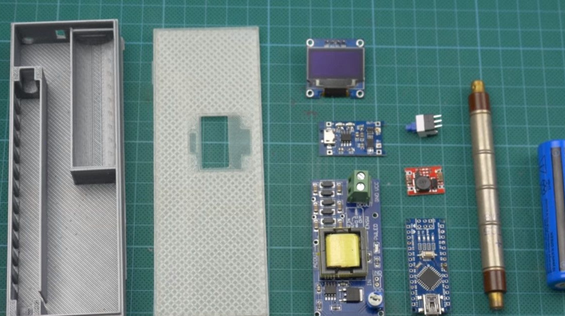
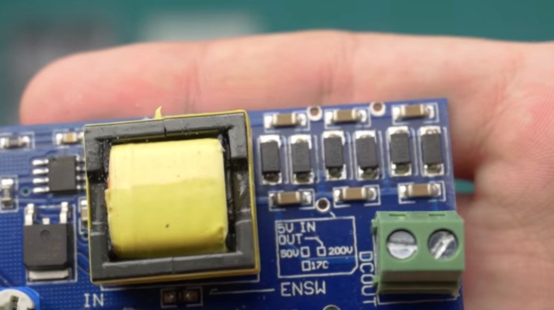
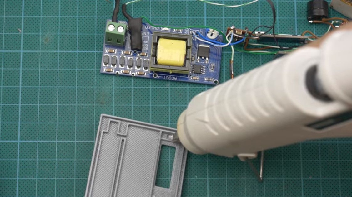
Boost Converter.
Battery charge control board.
5 volt boost module.
Brain in the form of arduino nano.
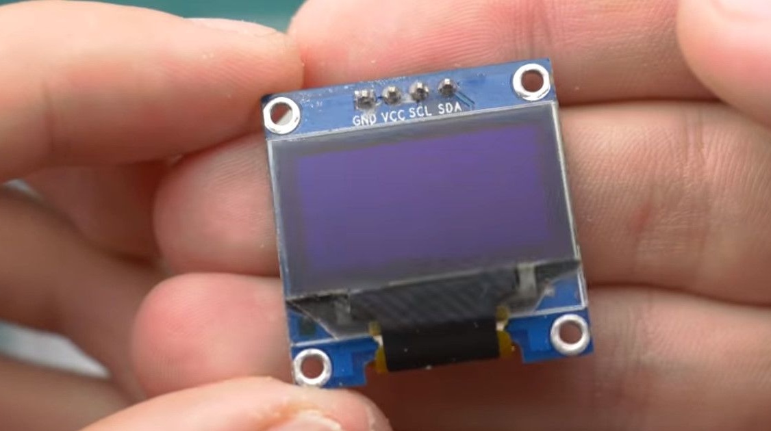
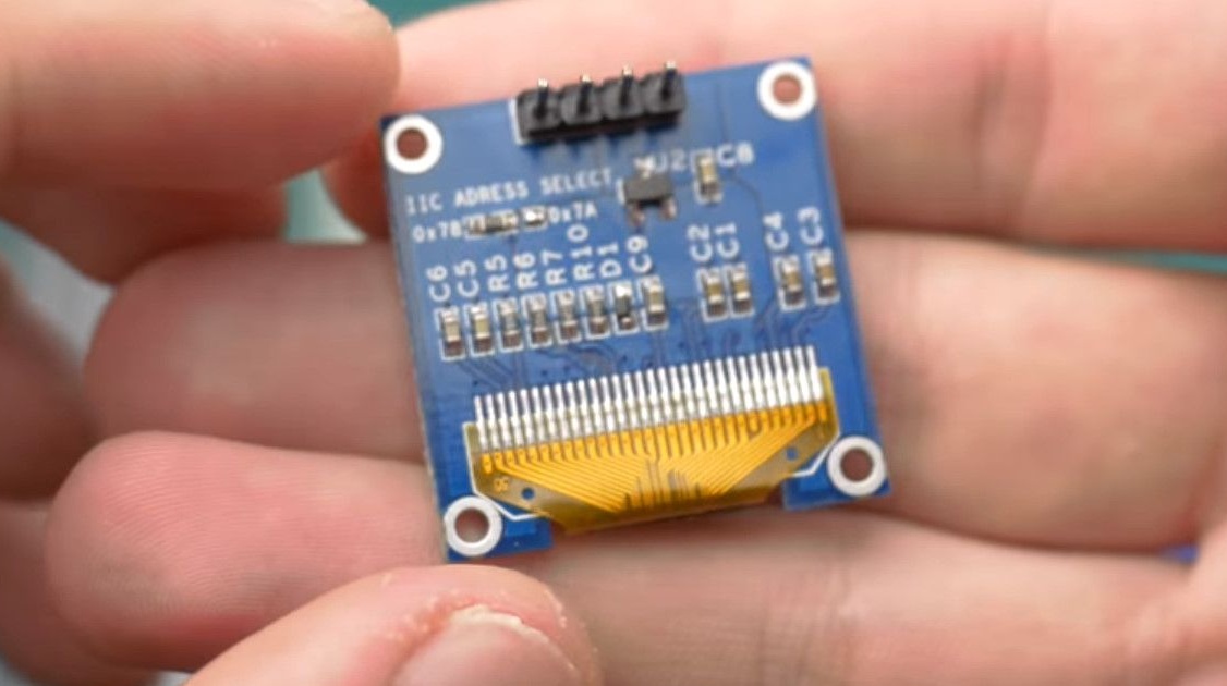
The display is 128 by 64, but in the end, 128 by 32 pixels will be applied.
It will also require 2N3904 transistors, 10MΩ and 10KΩ resistors, and a 470pF capacitor.
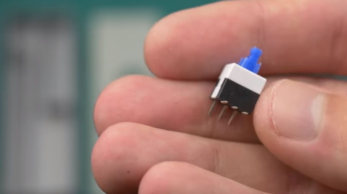
On-off switch.
Battery, buzzer with built-in generator.
And, of course, the main element is the Geiger counter applied model STS5.
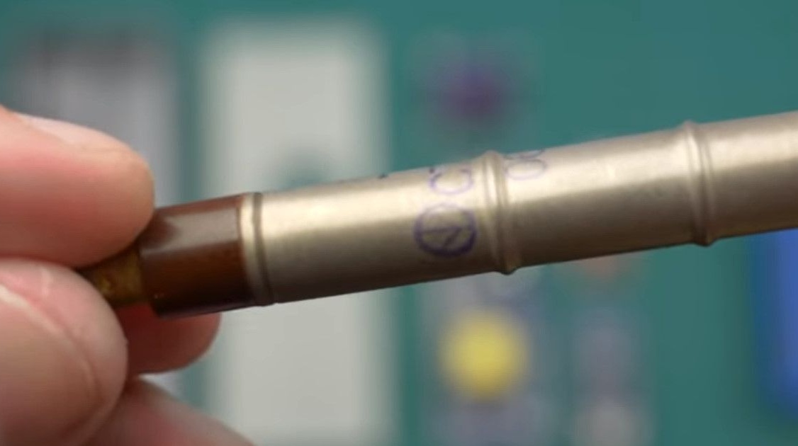
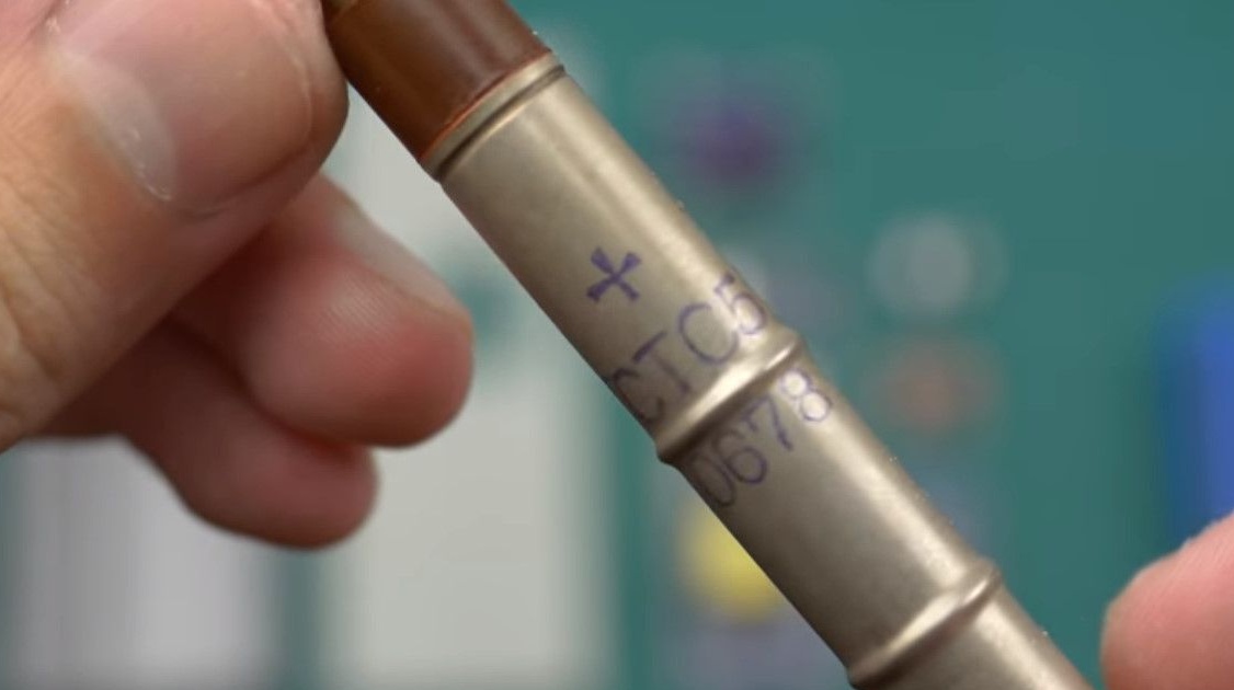
It can be replaced by a similar one, SBM20, and, in principle, any similar one.
When replacing the counter, it will be necessary to make adjustments to the program, according to the sensor documentation.
In the used STS5 counter, the number of micro-roentgen per hour corresponds to the number of breakdowns in the tube in 60 seconds.
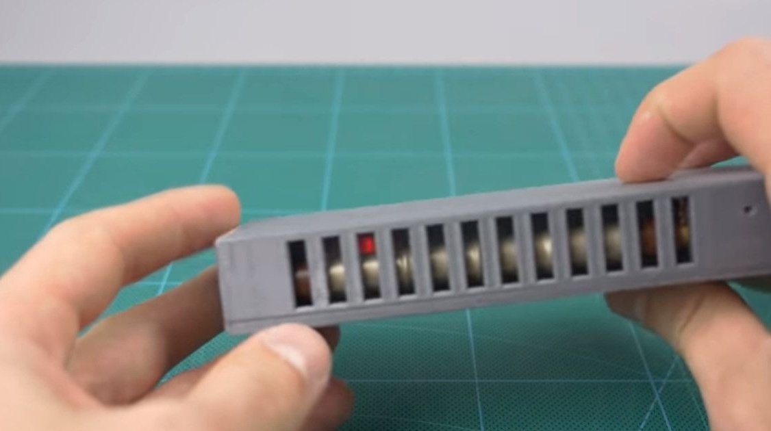
The case, as usual, is printed on a 3D printer.
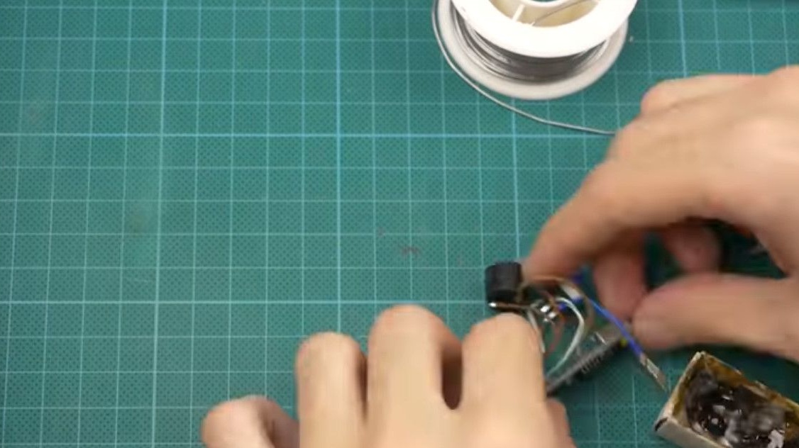
We begin to collect.
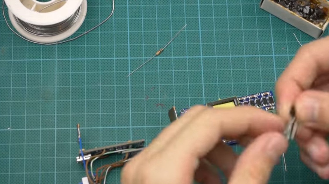
The first step is to set the output voltage of the converter using a trimming resistor.
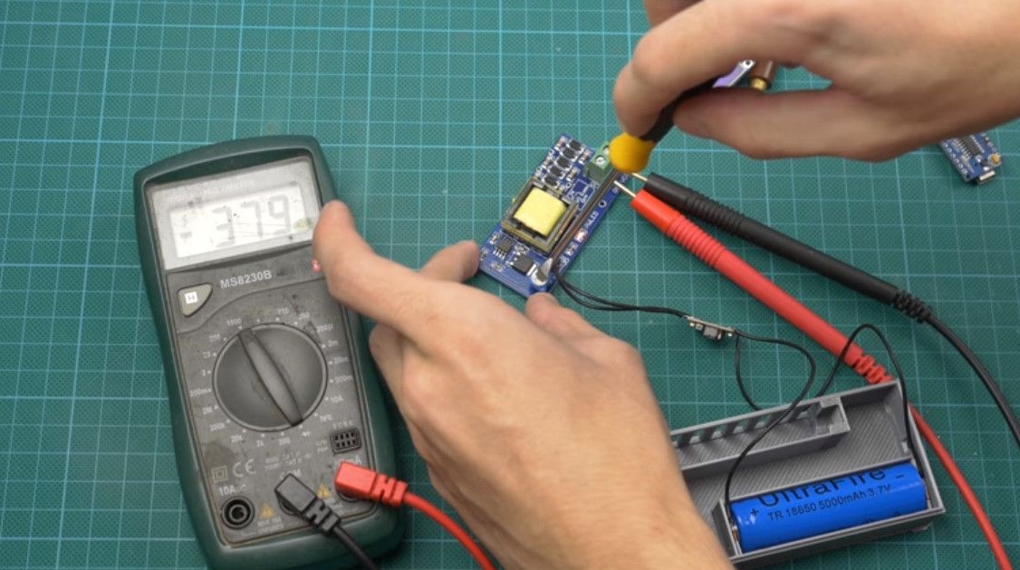
According to the documentation, for STS5 it is about 410 volts.
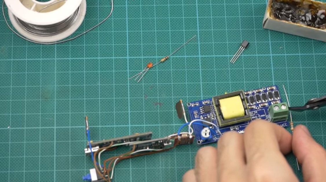
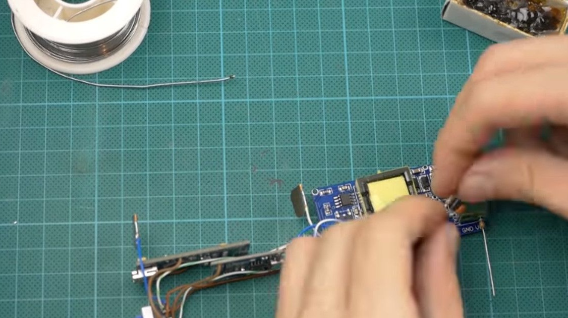
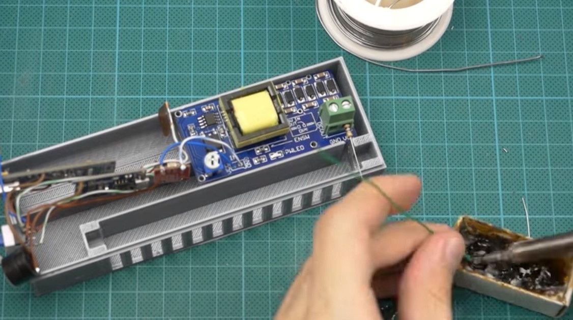
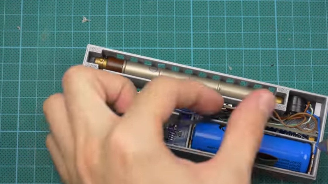
Next, we simply connect all the modules according to the scheme.
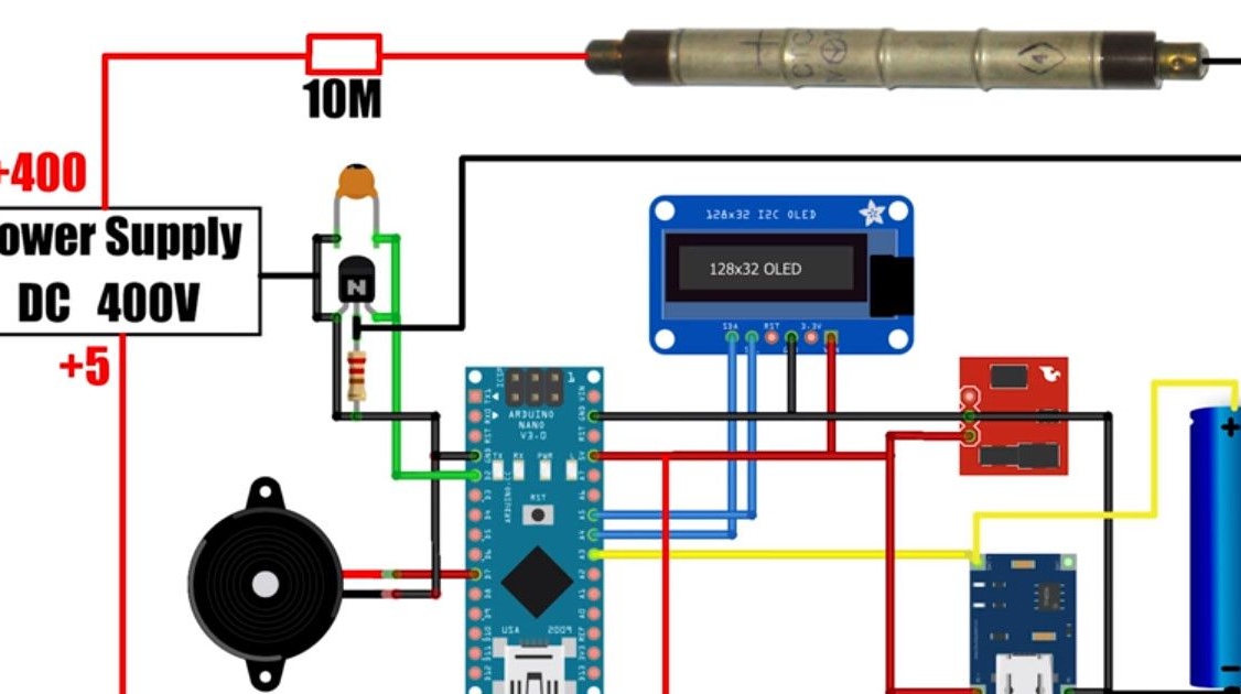
The modular principle simplifies circuitry to a minimum.
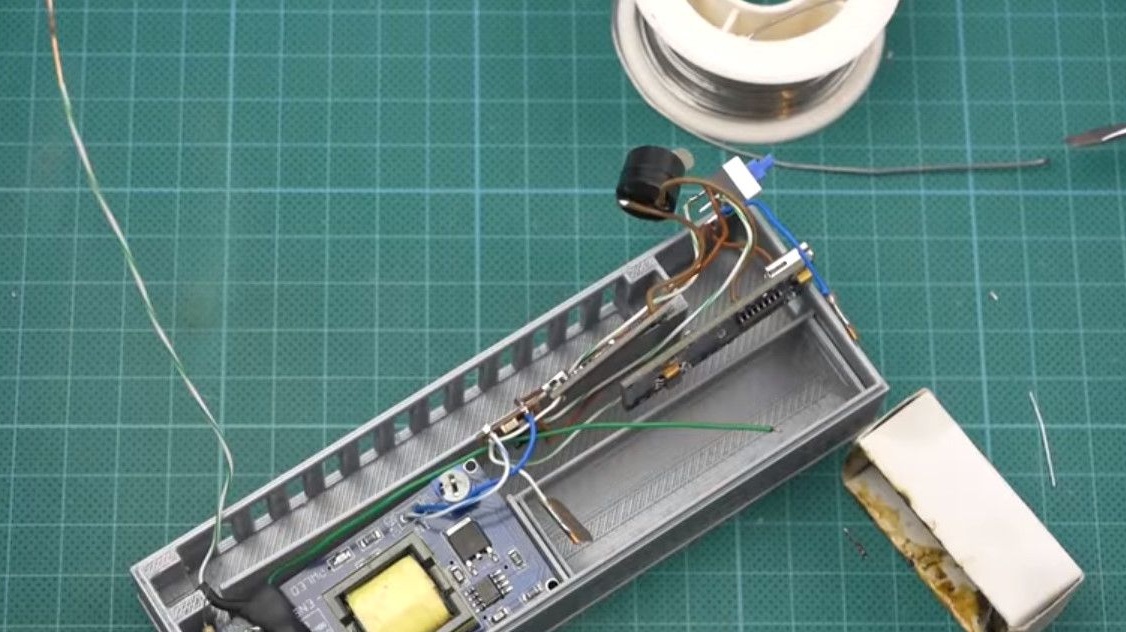
When assembling, it is desirable to use rigid single-wire wires, for example from twisted pair.
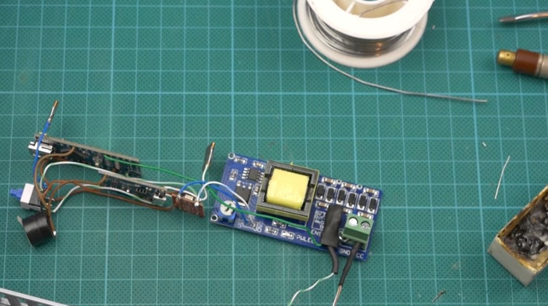
Thanks to them, the entire device is easy to assemble on a table.
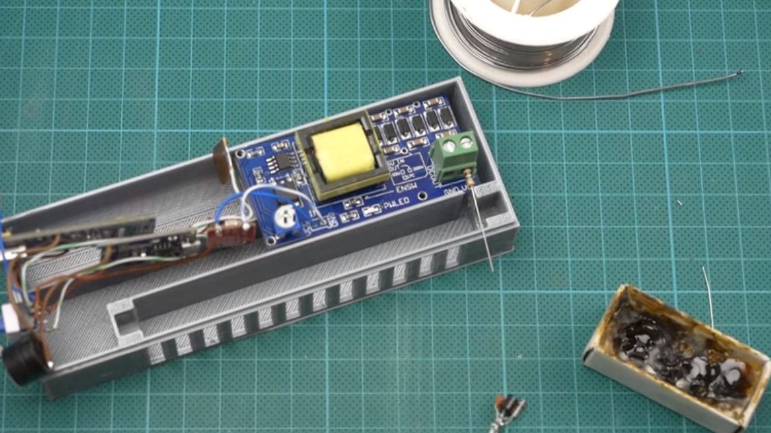
After assembly, just put it in the case.
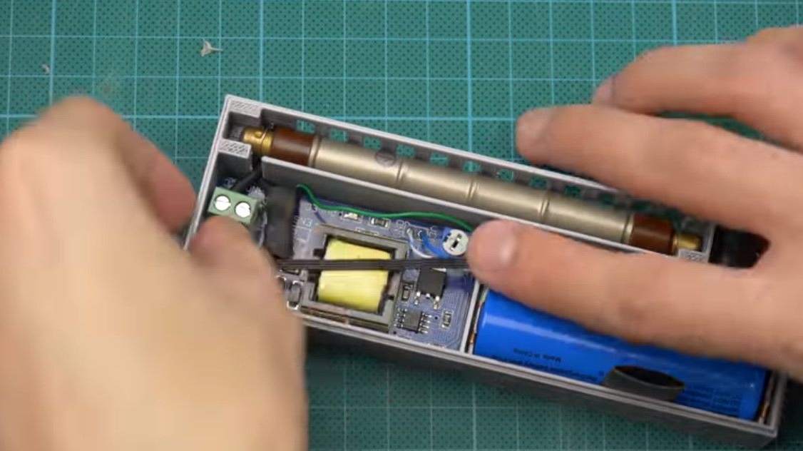
An important nuance. In order for our device to work, it is necessary to install a jumper on the high-voltage module.
We connect the minus of the input with the minus of the output.
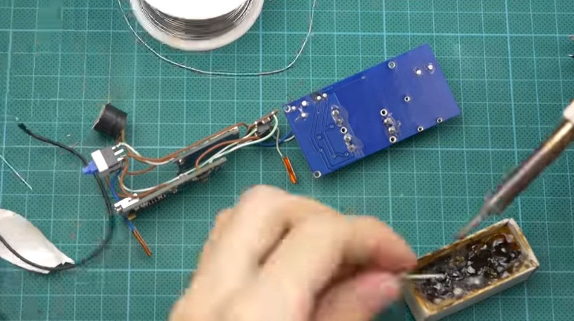
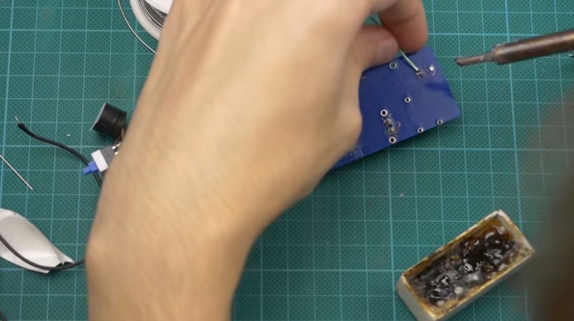
But we cannot control high voltage directly with the Arduino. To do this, we make the isolation circuit on the transistor.
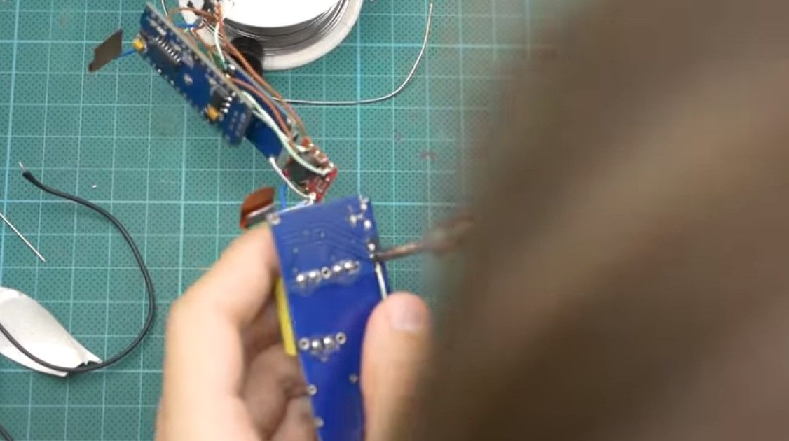
We solder with a hinged installation, insulate with hot melt adhesive or heat shrink, to whom it is more convenient.
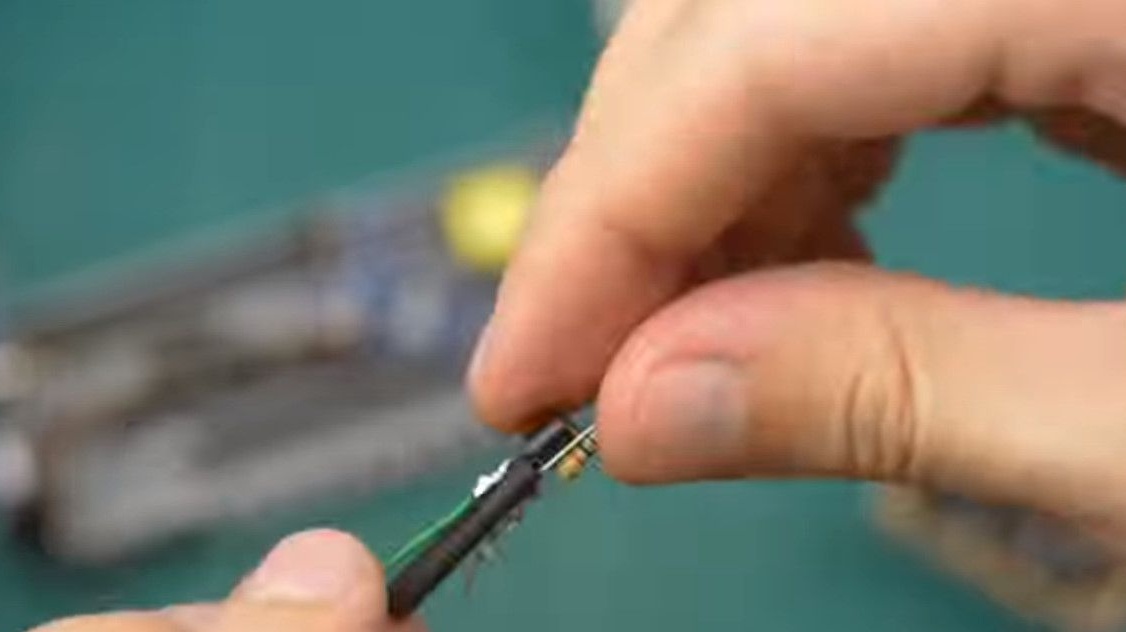
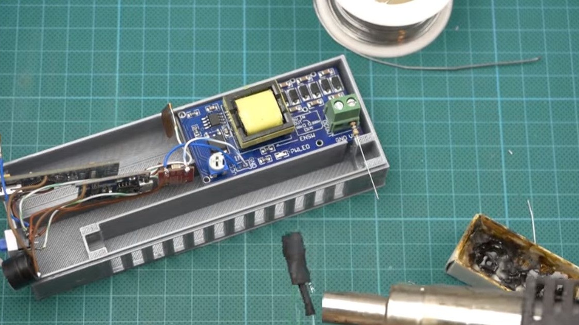
In the connector of the positive high-voltage output, we install a 10MΩ resistor.
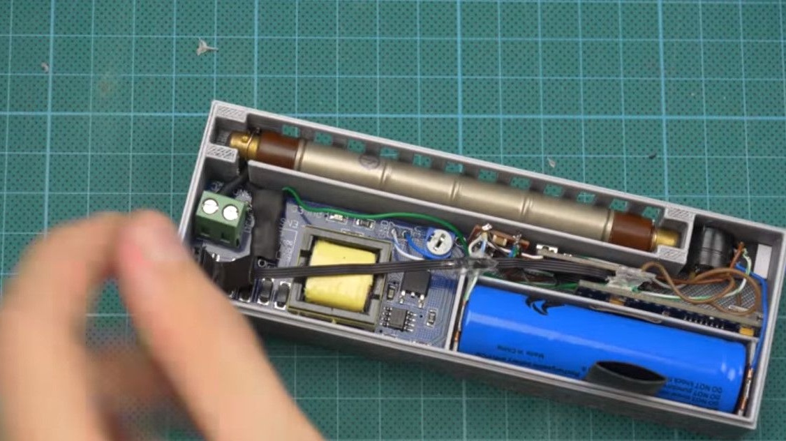
It is advisable to make the terminals for connecting the tube itself from copper foil.
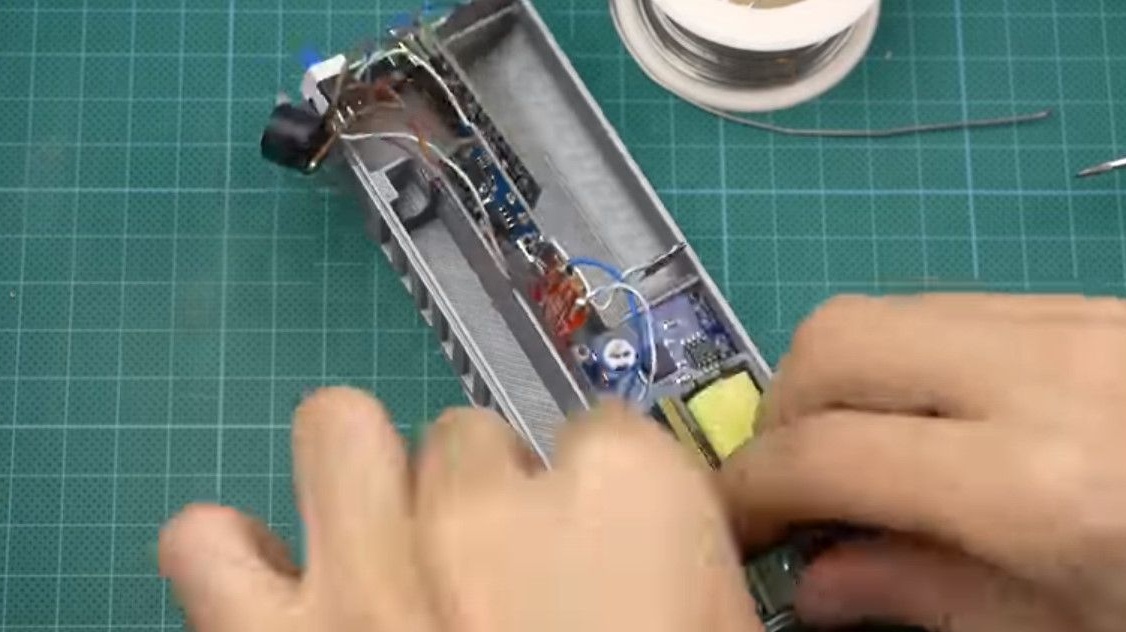
But for tests, you can fix it on twists. Observe the polarity of the tube.
We install the display, connect it with a loop with connectors.
Check the insulation very well, the screen is located next to the high-voltage module.
Mounting is ready, we install the entire structure in the housing.
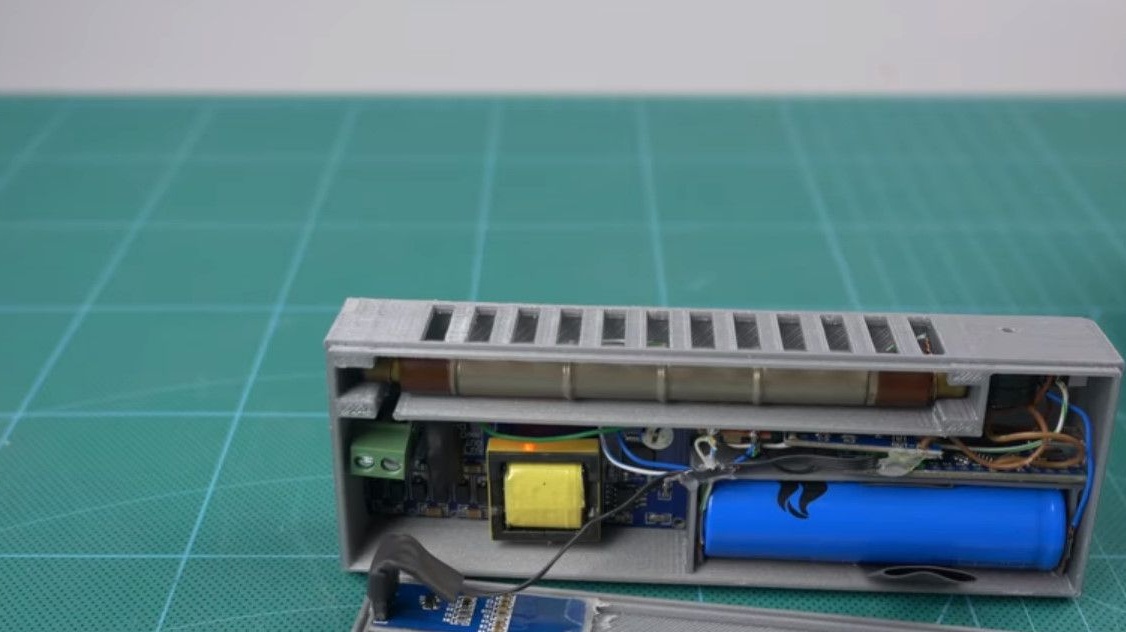
Everything is finished, the device shows a normal background radiation.


Links to components.
128 * 32 OLED
The Geiger counter was introduced for you by the author of the project, Konstantin, How-todo workshop.