

Greetings to all metal seekers. In this article I want to share my experience in assembling a wonderful pinpointer Toddler FM2V2, which has high stability and is able to distinguish non-ferrous metal from black. Such a device will become an indispensable tool for lovers of wandering around with a metal detector in search of treasures, as well as good entertainment for your children.
Before proceeding with the assembly of the pinpointer, I want to note that this design is made using a series microcontroller Pic. If you have difficulty programming pic controllers, I advise you to start to master this skill or turn to someone who is already in the subject. In any case, the game is worth the candle, as homemade shows high stability results and will become a real assistant, facilitating the work of the digger. Figure 1 shows the electrical circuit of this miracle device.
Before proceeding with the assembly of the pinpointer, I want to note that this design is made using a series microcontroller Pic. If you have difficulty programming pic controllers, I advise you to start to master this skill or turn to someone who is already in the subject. In any case, the game is worth the candle, as homemade shows high stability results and will become a real assistant, facilitating the work of the digger. Figure 1 shows the electrical circuit of this miracle device.
Figure 1 - electrical diagram of the pinpointer
In general, the scheme can be divided into several blocks, namely:
- block voltage Converter, made on a linear stabilizer LM317L. This approach made it possible to increase the stability of the device over a wide range of supply voltage, even when the latter was reduced to 5V.
- a sound indication unit about the presence of a metal object near the coil, which is made using a amplifying transistor T2 and speaker SP1.
- light indication unit, as an addition to the sound. The block is made on the LEDs Led1 and Led2. Led1 indicates the presence of non-ferrous metal near the coil, Led2 - black.
- generator block on transistors T1 and T3. Such a circuit solution provides automatic adjustment of the resonant frequency to the sensor parameters and high thermal stability.
- Central control unit based on a PIC12F675 or PIC12F629 microcontroller. Firmware for each type of controller goes separately and differs only in that for PIC12F675 a sound indication mode is added when the battery is lower than 5.5V. Otherwise, all functions are identical and you can take the controller, which is easier to get in place.
The following is a list of radio elements used in the circuit.
- R1, R6, R7, R11 - 10k
- R2 - 51 ohms
- R3 - 100 Ohms
- R4 - 560 Ohm
- R5, R9, R12 - 1 kOhm
- R8 - 220 kOhm
- R10 - 220 Ohm
- R13 - 3 kOhm
- D1 - 1N4007
- LED1 - green (non-ferrous metal)
- LED2 - red (ferrous metal)
- C1 - 33 nF (necessarily film)
- C2 - 1000 uF at 16V
- C3 - 10 uF at 6.3 V
- C4, C5 - 15 pF
- C6 - 100 nF
- T1, T3 - BC557
- T2, T4 - BC547
- VR1 - LM317L
- SP1 - a booster without an internal generator (suitable from a PC motherboard)
- Cr1 - 20 MHz thermostable quartz resonator
- But1 - a clock button without fixing
- IC1 - PIC12F675 or PIC12F629 (each of these microcontrollers has its own separate firmware.)
Download firmware for PIC12F675:
Download firmware for PIC12F629:
Since this device was originally conceived as a pinpointer, the following requirements were identified: the compact size of the board and search coil, a monolithic cylindrical body. The water pipe was ideal for the body PVCdiameter 25mm. From here the requirements for the printed circuit board were determined. Its width should not exceed the internal diameter of the pipe, and the height of the sealed elements should not prevent the board from freely entering the case. Achieve compact sizes SMD Elements. As a result, the etched board looks as follows (photo No. 2).
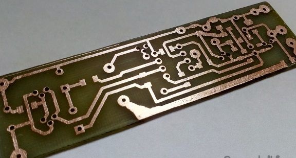
Photo No. 2 - the appearance of the printed circuit board
The board is designed so that SMD elements are installed on the side of the tracks, and the output elements are on the opposite side. Photo 3 shows a board with sealed SMD elements. They all have size 1206.
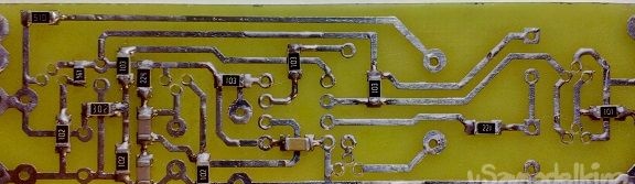
Photo No. 3 - pinpointer board with sealed SMD elements
For a microcontroller, it is better to use a socket Dip8, to always be able to extract it and reflash if something goes wrong. I also repeat that the capacitor C1 on the 33 nF it is better to use film, this will provide additional stability of the generator frequency when the ambient temperature changes. There are no special requirements for other elements. Photo 4 shows the view of the board from the side opposite to the tracks.
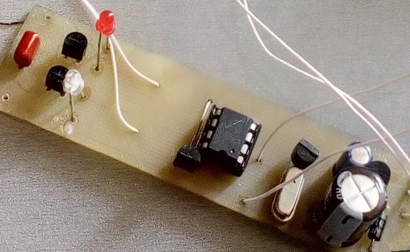
Photo No. 4 - board on the side of mounting the output elements
So, we figured out the board, but this is not enough. There are several more steps ahead before getting the finished pinpointer. One of these steps is the manufacture of a sensor (coil). This is a rather painstaking task, which requires some preparation and preliminary calculations.
To begin with, let's determine the diameter of the wire that is available and the diameter of the coil itself. In my case, there was an enameled copper wire with a diameter 0.4mm. As for the diameter of the coil, the following rules must be taken into account: the larger the diameter, the more sensitive the device, i.e. he is able to detect a metal object at a farther distance, and vice versa, with a decrease in diameter, sensitivity decreases. Since my plans were to use the housing 25mm, it was decided to wind the coil on the rim, diameter 20mmto be able to hide it inside the case. Water pipe was ideal for the mandrel 20mm and a pair of lids from eggplant with water, the distance between which is about 10mm. (photo No. 5).
To begin with, let's determine the diameter of the wire that is available and the diameter of the coil itself. In my case, there was an enameled copper wire with a diameter 0.4mm. As for the diameter of the coil, the following rules must be taken into account: the larger the diameter, the more sensitive the device, i.e. he is able to detect a metal object at a farther distance, and vice versa, with a decrease in diameter, sensitivity decreases. Since my plans were to use the housing 25mm, it was decided to wind the coil on the rim, diameter 20mmto be able to hide it inside the case. Water pipe was ideal for the mandrel 20mm and a pair of lids from eggplant with water, the distance between which is about 10mm. (photo No. 5).
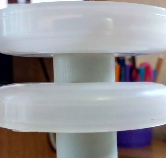
Photo No. 5 - Mandrel for winding a coil (d = 20mm)
When the technical part is ready, the question arises, how many turns to wind? The program will help to answer this question. Coil32. Download the program on, run and perform a series of actions below.
First, unpack the archive with the program and run the file Coli32.exe. After that, the main window appears, shown in screenshot No. 6
First, unpack the archive with the program and run the file Coli32.exe. After that, the main window appears, shown in screenshot No. 6
Screenshot 6 - Coil32 program after launch
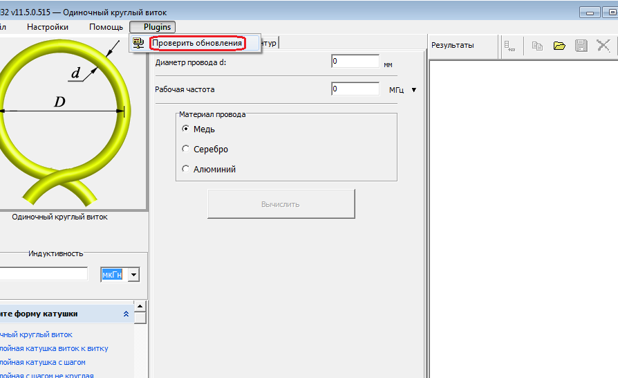
In the initial state, the program does not have plugins for the calculations we need. Therefore, they need to be downloaded. The program itself allows you to do this. To do this, go to the menu "Plugins"and select"Check for Updates", as shown in the screenshot above. After that, the corresponding window shown in screenshot No. 7 will open.
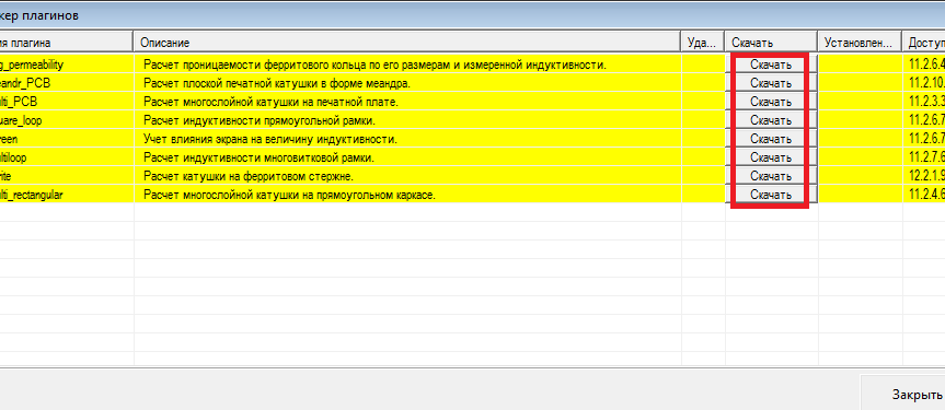
Screenshot 7 - Plugin Manager
Install all the plugins offered by the program using the buttons "Download"and close the manager. The program will ask you to restart, we agree and after restarting again go to the menu"Plugins"Now here is a whole list of additional calculators from which we need only one with the name "Multi loop"(screenshot number 8)
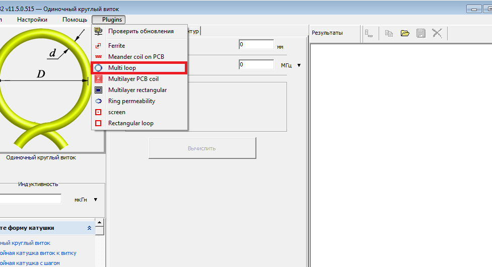
Screenshot No. 8 - selection of the necessary plug-in for calculating the pinpointer coil
In the window that appears, fill in the cells with the necessary parameters, namely:
- Inductance - 1500 μH (L1 coil in the diagram)
- The inner diameter D is 20mm (as discussed above, I make a small coil)
- Wire diameter d - 0.4mm (I only had one in stock)
After that, we click the calculate button and we get the result shown in screenshot No. 9:
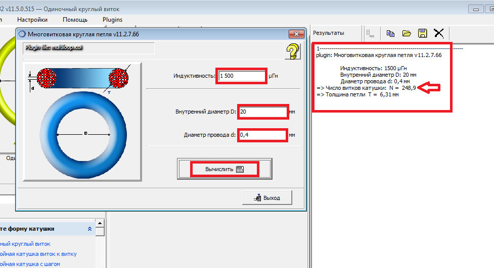
Screenshot 9 - result of calculation of coil parameters for pinpointer
As can be seen from the screenshot, you need to wind 249 turns of wire 0.4mm on the 20 millimeter rim to get the treasured 1500mcHthat the scheme requires from us. We will not argue - we will wind ...
To somehow facilitate the winding process, I have assembled a masterpiece of engineering from a children's table, a small vice, and other improvised trash. The result is shown in photo No. 10.
To somehow facilitate the winding process, I have assembled a masterpiece of engineering from a children's table, a small vice, and other improvised trash. The result is shown in photo No. 10.
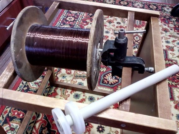
Photo No. 10 - preparation for coil winding
Immediately I notice that the coil is wound in bulk. It makes no sense to try to lay turns, but still it is better to distribute the wire evenly over the entire winding area. For the convenience of counting turns, it is better to put a mark on the restrictive end - it is easier to track each revolution passed. During winding, it is better to turn off the mobile phone and close in a separate room so that no one can get off the account. After the work is done, it is necessary to carefully remove the coil from the frame and pull it with threads around the entire perimeter, as shown in photo No. 11.
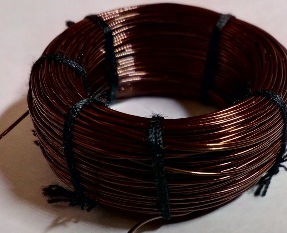
Photo No. 11 - Freshly baked pinpoint reel
To add strength to the coil and prepare it for shielding, we wrap it with ordinary stationery tape, as shown in photo No. 12
Photo No. 12 - preparation for shielding
Since the pinpointer works on the principle of measuring the frequency of the oscillating circuit, this implies high requirements for frequency stability and protection from interference. If the frequency of the generator provides us with stability, then shielding the coil will provide protection from interference.
For shielding, you can use ordinary food foil, which is almost everyone in the kitchen or something like that. Foil the coil, leaving a small empty sector in the area of its findings. This is required in order not to get a short-circuited loop through which the signal will not pass at all. A stripped copper wire is additionally wound on top of the foil, which will subsequently be soldered to the general minus on the board. Below is a photo No. 13, which clearly shows the screening process.
For shielding, you can use ordinary food foil, which is almost everyone in the kitchen or something like that. Foil the coil, leaving a small empty sector in the area of its findings. This is required in order not to get a short-circuited loop through which the signal will not pass at all. A stripped copper wire is additionally wound on top of the foil, which will subsequently be soldered to the general minus on the board. Below is a photo No. 13, which clearly shows the screening process.
Photo 13 - shielded coil
To keep this whole thing from falling apart, you need to strengthen the coil with another layer of adhesive tape or electrical tape. And only after that you can relax and consider the coil completely ready. The result of my efforts is shown in photo No. 14.
Photo No. 14 - a completely ready coil
Most of the work is done. We solder everything into a single whole and check the operation of the pinpoint on the table. The best battery for powerKRONA"with a special holder for it. My pinpointer worked the first time and I didn’t find any difficulties. Even with a coil flattened under the future case, it works stably (photo No. 15)
Photo No. 15 - pinpointer is ready for placement in the housing
Since the pinpointer is supposed to be used in harsh field conditions, it needs a strong and airtight housing. In my opinion, the most optimal and affordable option is to use tap water PVC pipe diameter 25mm and about 25cm. It lies perfectly in the hand and easily accommodates all the elements of the device. Also, one of the ends of the pipe is cut off at an angle of about 60 degrees. This will allow you to place the coil at an angle convenient for searching and will make it possible to split earth lumps with a pointed end. Photo No. 16 shows the appearance of my case.
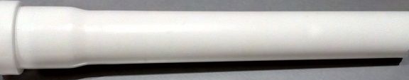
Photo No. 16 - casing from a water pipe
I decided to take the power switch and reset button out and attach it at the base of the pipe. Also, do not forget about the LEDs - holes should be made for them in a place convenient for perception - I have them located approximately in the center. I didn’t make a hole for the speaker, it is already perfectly audible. Below, in photo No. 17, a method of attaching a switch and a reset button is shown.
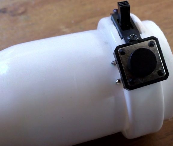
Photo No. 17 - mounting location of the switch and reset button
A coil is mounted on the opposite side. To fix it inside the pipe, I used hot glue. And in order to close it from mechanical damage - I cut out a plug from the PCB in the form of a slice. The result is shown in photo No. 18.
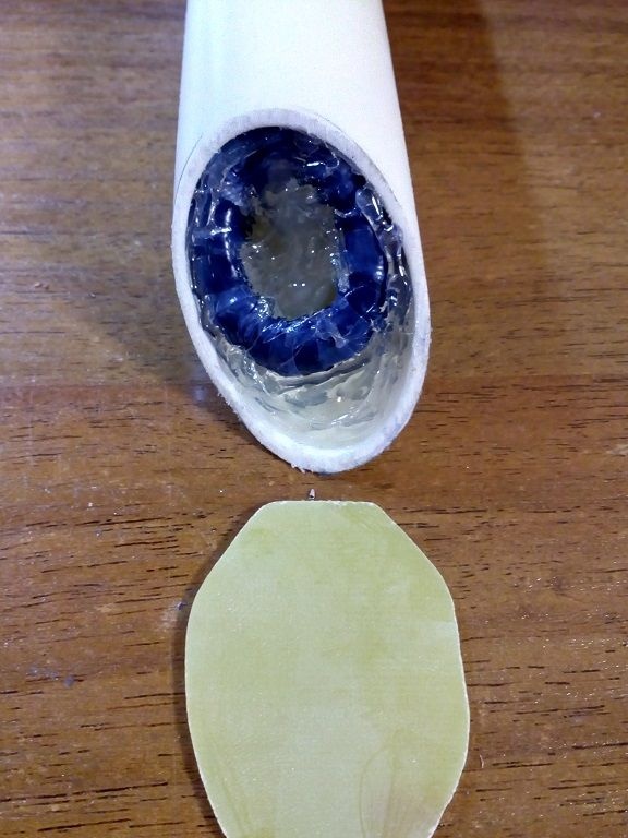
Photo No. 18 - mounting of the coil and plug made of textolite
After the hot melt has cooled, you can glue the plug. This is best done with super-glue, sprinkling loose-fitting places with ordinary baking soda. When super-glue and baking soda interact, a solid substance is formed that resembles glass. In this way, you can eliminate all the cracks in the pinpoint housing. The sizing result is shown in photo No. 19.
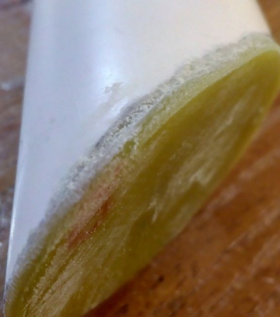
Photo No. 19 - fastening the plug with super-glue and soda
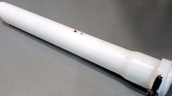
The back side of the device is covered with foam rubber cut along the diameter of the pipe. You can of course buy a stub, but everything is fine with me already. In general, the device turned out to be ergonomic, fits well in the hand and does not take up much space. A general view of the finished pinpointer is shown in photo No. 20.
Photo No. 20 - appearance of the finished pinpointer
Well, in the end I want to give two video tests, without which the article would not be complete. I advise everyone to have such an assistant with them.
Testing for metal differences:
[media = https: //www.youtube.com/watch? v = k2A3dyajoE4]
Range Testing:
[media = https: //www.youtube.com/watch? v = lLJv1Y4CW5U]