

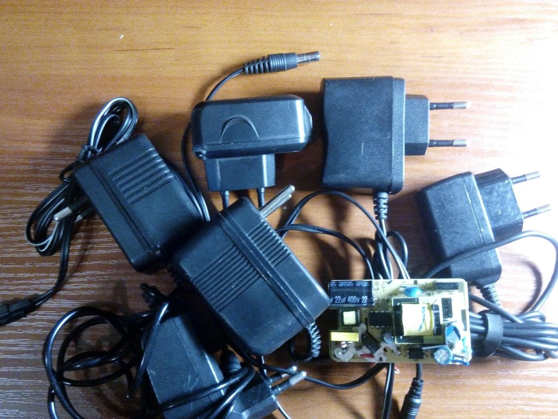
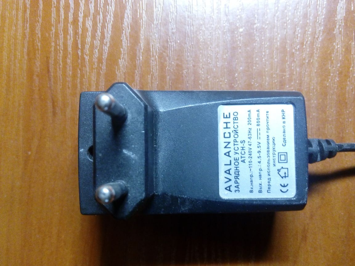
Over time, I accumulated a certain number of different Chinese AC-DC converters for charging the batteries of mobile phones, lights, tablets, as well as small switching power supplies for electronic crafts and actually the batteries themselves. On the cases, the electrical parameters of the device are often indicated, but since most often it is necessary to deal with Chinese products, where it is sacred to overestimate the performance, it would not be out of place to check the real parameters of the device before using it for crafts. In addition, it is possible to use power sources without a case, on which information about their parameters is not always available.
Many may say that it’s enough to use powerful variables or constant resistors, car lamps or simply nichrome spirals. Each method has its drawbacks and advantages, but the main thing is that using these methods of smooth adjustment of current is quite difficult to achieve.
Therefore, I collected for myself the electronic load on the operational amplifiers LM358 and the composite transistor KT827B with testing power supplies with voltage from 3 V to 35 V. In this device, the current through the load element is stabilized, so it is practically not subject to temperature drift and does not depend on the voltage of the source under test, which is very convenient when removing load characteristics and performing other tests, especially long ones.
Materials:
- chip LM358;
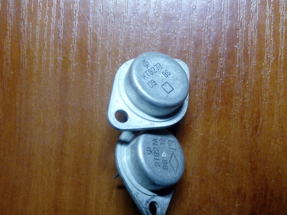
- transistor KT827B (composite NPN transistor);
- resistor 0.1 Ohm 5 W;
- 100 ohm resistor;
- 510 ohm resistor;
- 1 kΩ resistor;
- resistor 10 kOhm;
- variable resistor 220 kOhm;
- non-polar capacitor 0.1 μF;
- 2 pcs oxide capacitor 4.7 uF x 16V;
- oxide capacitor 10 uF x 50V;
- aluminum radiator;
- stable power supply 9-12 V.
Instruments:
- soldering iron, solder, flux;
- electric drill;
- jigsaw;
- drill;
- tap M3.
Assembly Instructions for the device:
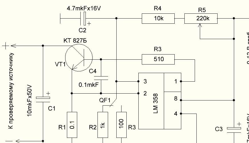
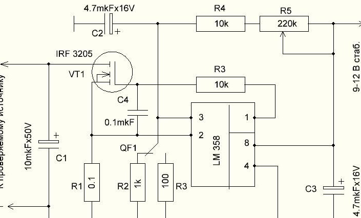
Operating principle. The device by the principle of operation is a current source that is controlled by voltage. A powerful KT 827B composite bipolar transistor with a collector current of Ik = 20A, a gain of h21e of more than 750 and a maximum power dissipation of 125 W is the equivalent of a load. 5W resistor R1 - current sensor. Resistor R5 changes the current through resistor R2 or R3 depending on the position of the switch and, accordingly, the voltage on it. An amplifier with negative feedback from the emitter of the transistor to the inverting input of the operational amplifier is assembled on the LM358 operational amplifiers and the KT 827B transistor. The effect of the OOS is that the voltage at the output of the op-amp causes such a current through the transistor VT1 so that the voltage on the resistor R1 is equal to the voltage on the resistor R2 (R3). Therefore, the resistor R5 regulates the voltage across the resistor R2 (R3) and, accordingly, the current through the load (transistor VT1). While the op-amp is in linear mode, the indicated value of the current through the transistor VT1 does not depend either on the voltage on its collector or on the drift of the parameters of the transistor when it is heated. The R4C4 circuit suppresses the self-excitation of the transistor and ensures its stable operation in linear mode. To power the device, a voltage from 9 V to 12 V is required, which must be stable, since the stability of the load current depends on it. The device consumes no more than 10 mA.
Work sequence
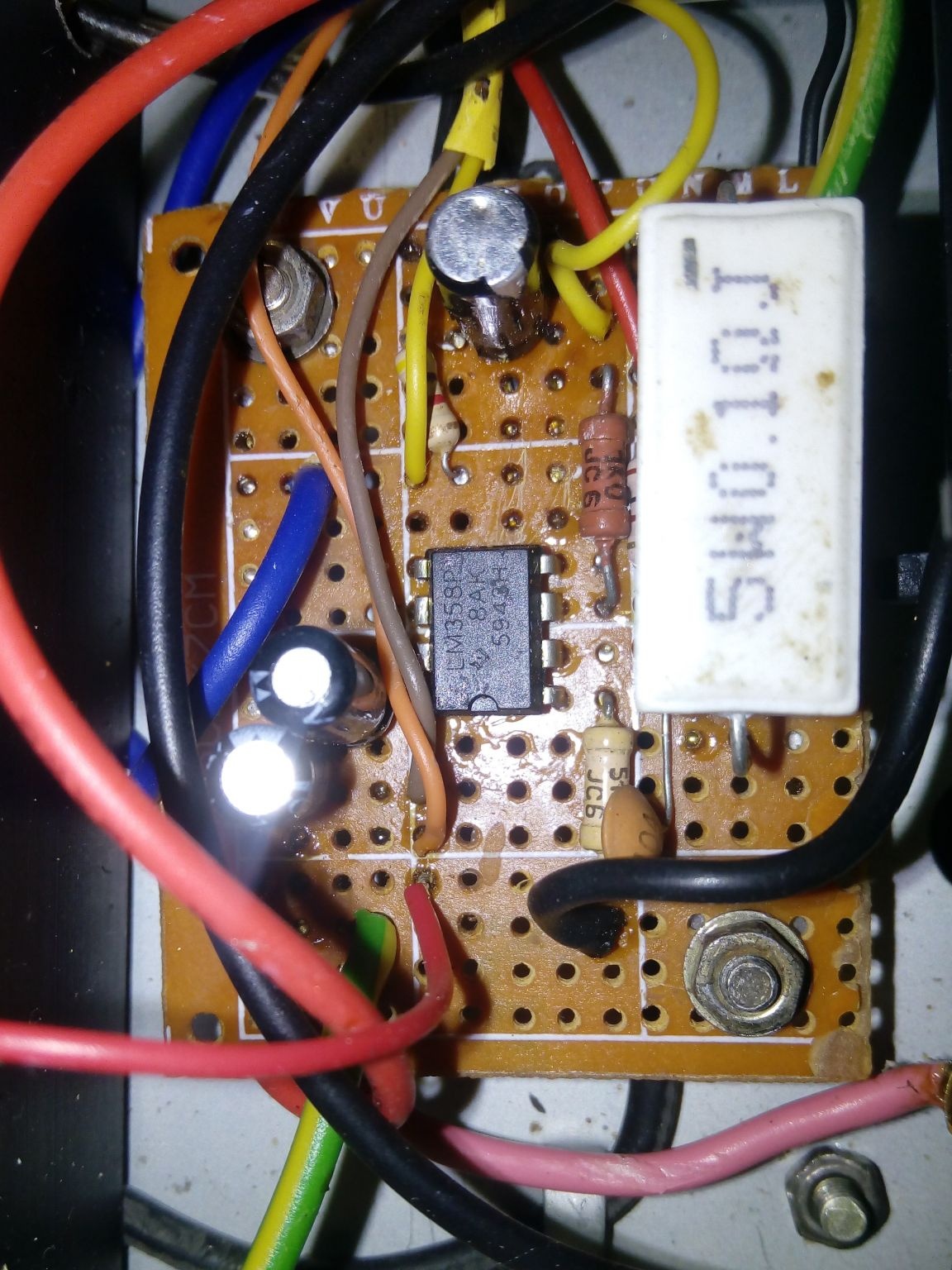
The electrical circuit is simple and does not contain many components, so I did not bother with the printed circuit board and mounted it on the breadboard. Resistor R1 raised above the board, as it is very hot. It is advisable to take into account the location of the radio components and not to place electrolytic capacitors near R1. I didn’t quite manage to do this (I lost sight of it), which is not entirely good.
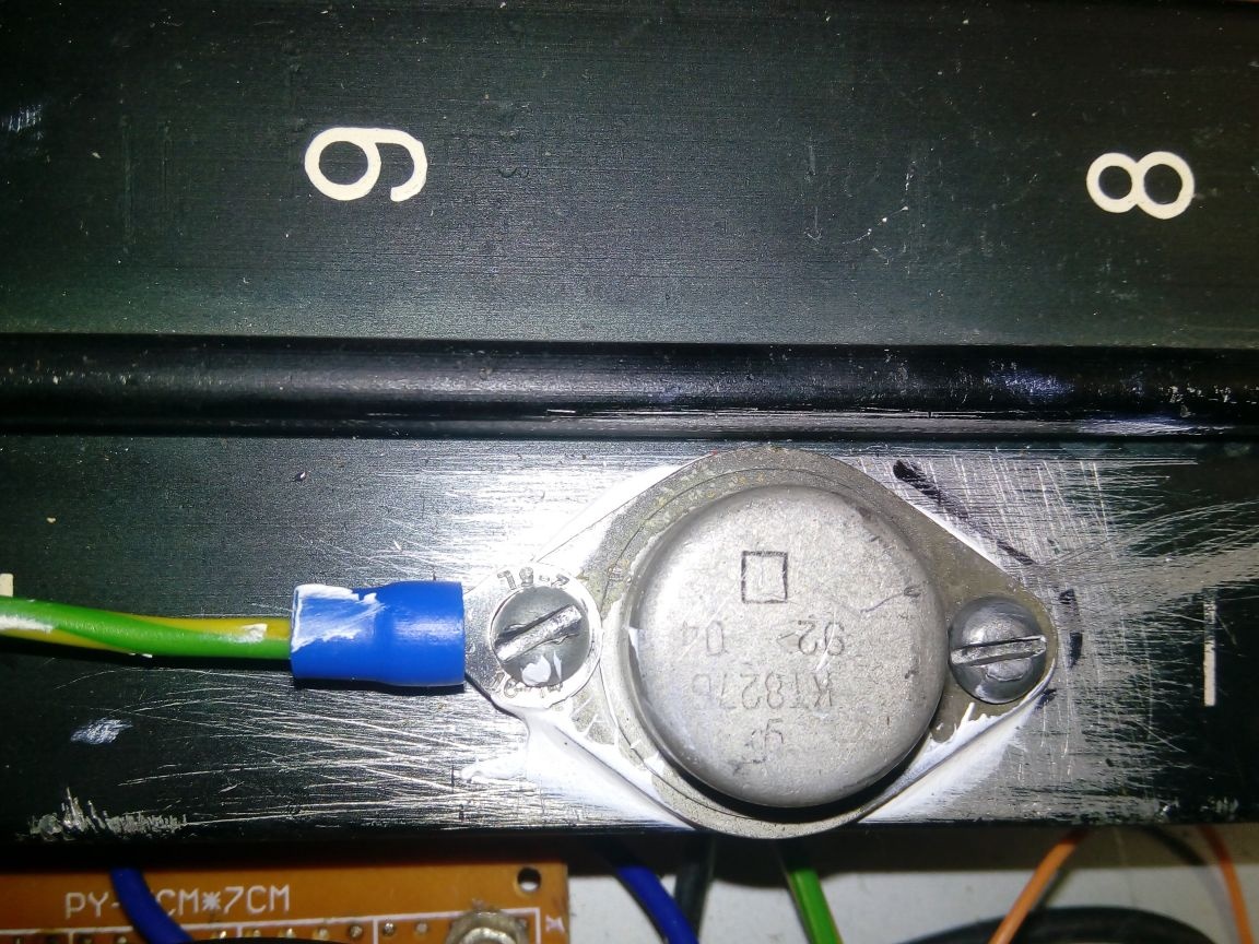
A powerful composite transistor KT 827B installed on an aluminum radiator. In the manufacture of a heat sink, its area should be at least 100-150 cm2 at 10 watts of power dissipation. I used an aluminum profile from some photo device with a total area of about 1000 cm2. Before installing the transistor, VT1 cleaned the heat sink surface from the paint and applied the KPT-8 heat-conducting paste to the installation site.
You can use any other transistor of the KT 827 series with any letter designation.
Also, instead of a bipolar transistor, you can use an IRF3205 n-channel transistor or other analog of this transistor in this circuit, but you must change the value of the resistor R3 to 10 kOhm.
But there is a risk of thermal breakdown of the field effect transistor with a rapid change in the passing current from 1A to 10A. Most likely, the TO-220 case is not able to transfer such an amount of heat in such a short time and boils from the inside! To everything you can add that you can still run into a fake radio component and then the parameters of the transistor will be completely unpredictable! Either the aluminum housing of the KT-9 of the KT827 transistor!
Perhaps the problem can be solved by installing in parallel 1-2 of the same transistors, but I practically did not check - the very same number of IRF3205 transistors are not available.
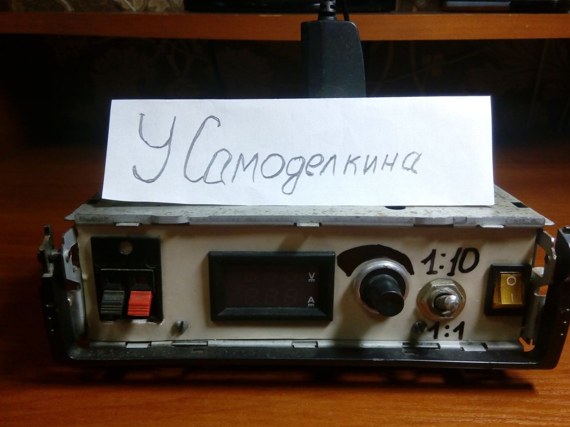
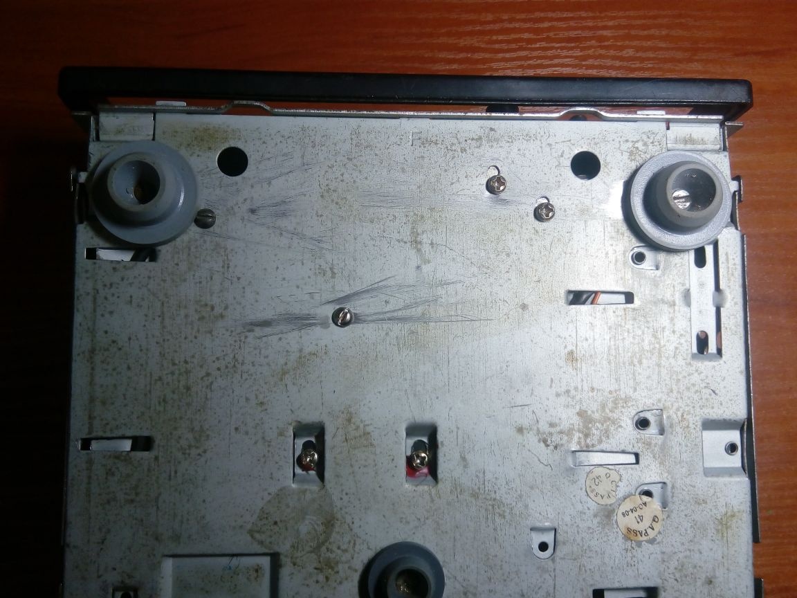
Housing for electronic load applied from a faulty car radio. A handle for carrying the device is present. Bottom mounted rubber feet to prevent slipping. As legs I used caps from bubbles for medical preparations.
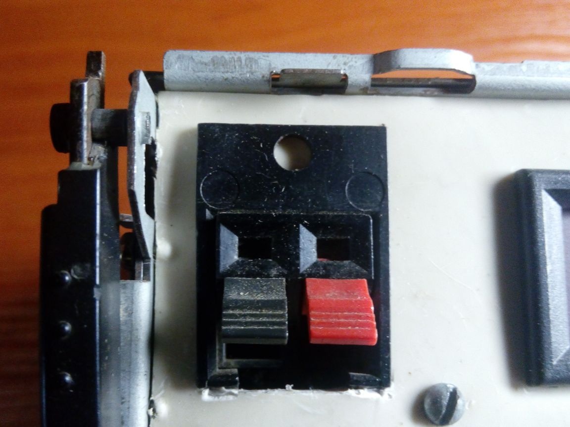
On the front panel for connecting power supplies placed a two-pin acoustic clip. These are used on audio speakers.
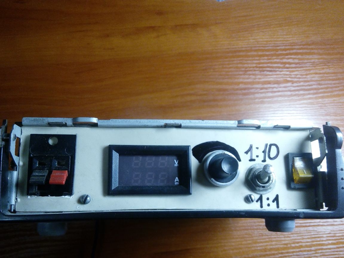
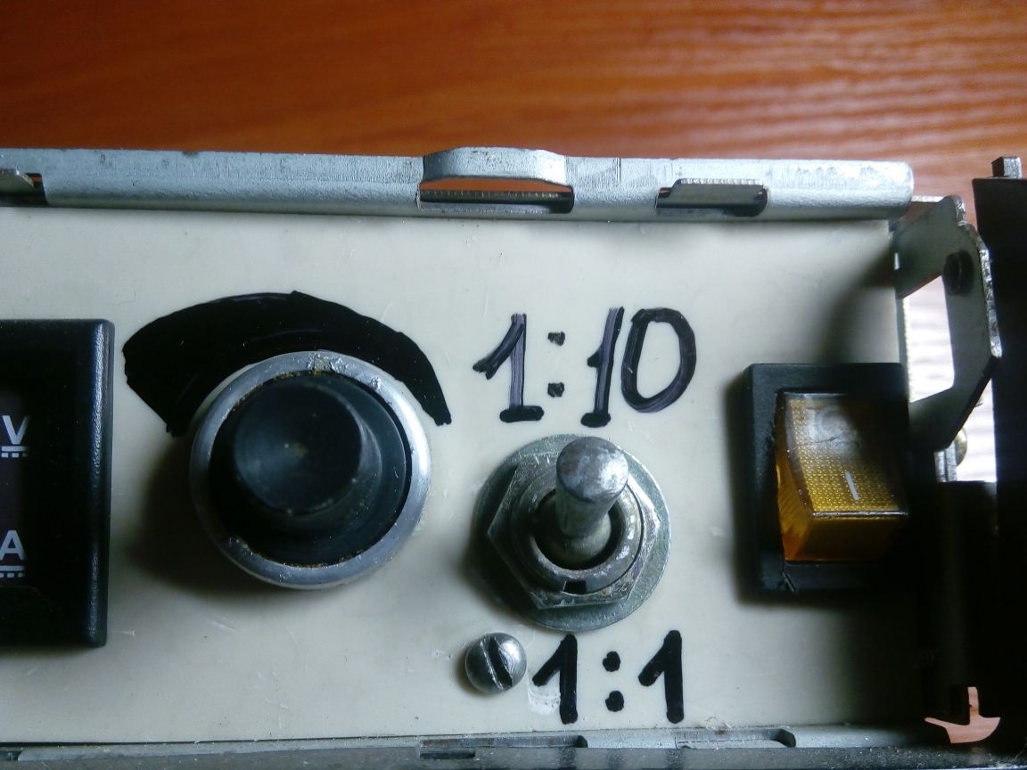
There is also a knob for the current regulator, a power on / off button for the device, an electronic load operation mode switch, an ammeter for visual monitoring of the measurement process.
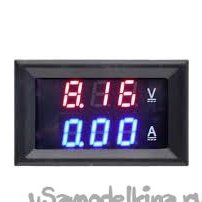
An ampervoltmeter was ordered on a Chinese site in the form of a ready-made embedded module.
The electronic load operates in two test modes: the first from 70 mA to 1A and the second from 700 mA to 10A.
The device is powered by a stabilized switching power supply voltage of 9.5 V.
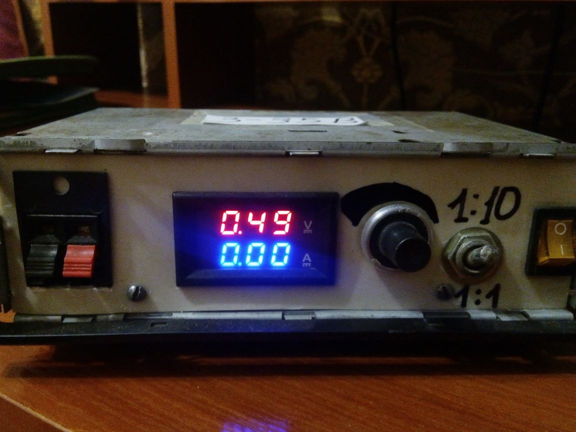
When connecting an electronic load, a 0.49V value is displayed on the ammeter (the value may vary). This is a feature of the operation of the LM358 operational amplifier and the KT827 composite transistor, but this does not affect the measurement accuracy in any way. If you want an aesthetic look, you can use a field effect transistor, then the readings will be 0 V. Once again I repeat - these values do not affect the measurement accuracy!
Conclusion
With this electronic load, I was able to squeeze about 100 watts with a 12V power supply, maybe more, but there is nothing to check. Smooth adjustment of current, minimum temperature drift and independence from the voltage of the tested source allows you to more accurately determine the characteristics of the tested power source.
This device is suitable for testing single power sources, but if you approach the matter wisely, you can create on its basis a multi-channel device for checking, for example, a computer power supply.