
Greetings the inhabitants of our site!
As you know, many home-made, as well as factory devices often do not have protection against improper inclusion of the power polarity, in other words, they do not have protection against power reversal. In particular, this applies to various homemade products, as well as to finished devices, sound amplifiers, mortise sound modules, etc.
Any user, by negligence, may accidentally invert the power polarity, after which in the vast majority of cases the device may require urgent help in the form of repair. And it may even happen that the device after such bullying will simply become worthless, and no repair will help to bring it back to life.
In order to avoid such an unpleasant situation, protection from reverse polarity should be used. They are different. One of the popular options is the use of diodes or diode bridges for power supply, which are capable of passing current in only one direction and thereby preventing the possibility of polarity reversal. This is a fairly budgetary and most simple solution. But there is a minus to this method of protection, namely, the presence of a voltage drop across the diode. Do not forget also that at high currents and the presence of a voltage drop, the diodes heat up rather weakly and if cooling is not used, they can fail.
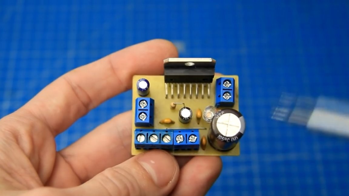
For example, a diode bridge is installed on this sound amplifier with a TDA7377 chip.
In this case, it is primarily used here as a voltage rectifier when powered by an alternating voltage current source. But if you connect the device to a power source with a constant voltage, then this diode bridge works exactly as protection against reverse polarity. And no matter how we connect the battery, the diode bridge will prevent reverse polarity by passing current in the right direction.
And if instead of the diode bridge there was just a diode in plus, then if the power is incorrectly connected (polarity reversal), the diode will not pass current and the amplifier simply will not turn on.
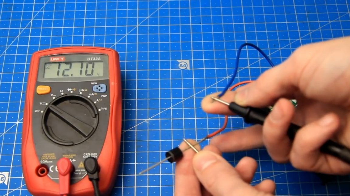
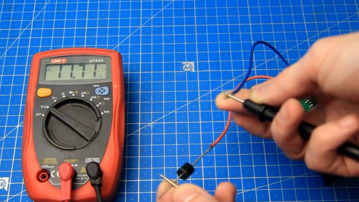
But, as mentioned above, both the diode bridge and the diode have a voltage drop. To demonstrate this, the author of the Radio-Lab YouTube channel measured the voltage before and immediately after the diode bridge.
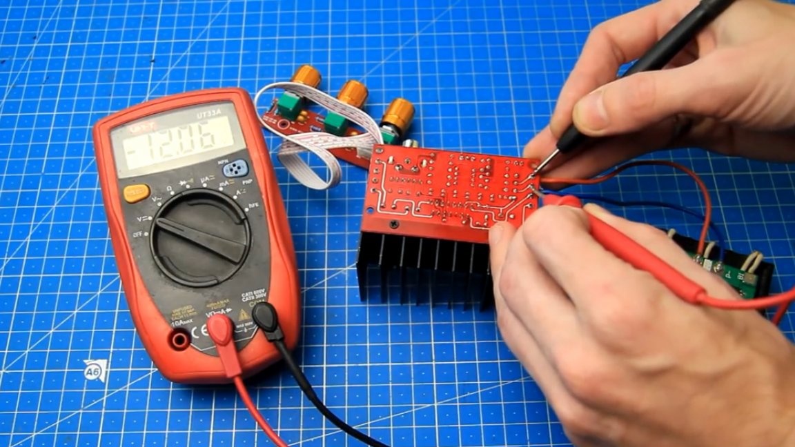
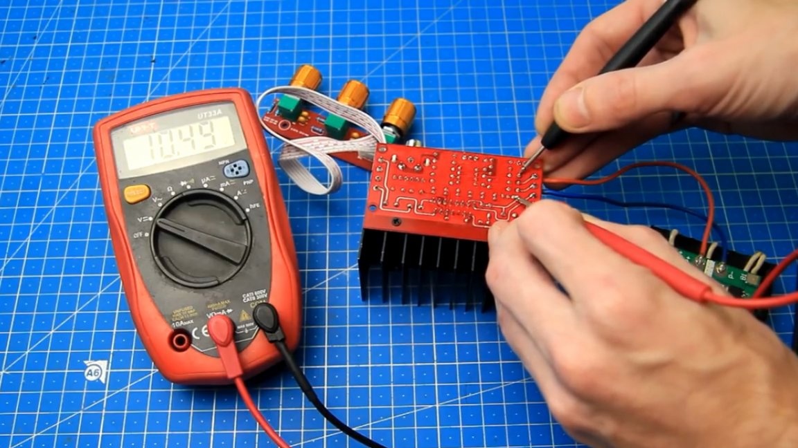
As you can see, the voltage on the battery is 12.06V, and already after the diode bridge the voltage is about 1.5V lower.It seems that the losses are not so big, but this in turn will affect the power of the amplifier, as a result, it will be slightly lower and part of the battery energy will be used to heat the diode bridge.
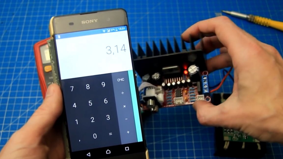
Let's calculate the loss and heat generation on a diode bridge. For example, when the load current is 2A and the voltage drop across the diode bridge is 1.5V, the heat generation on the diode bridge will be about 3W. And additional losses are not a plus, especially when powering the sound amplifier or other device from the battery, where it is advisable to spend energy sparingly and its amount in the battery is limited.
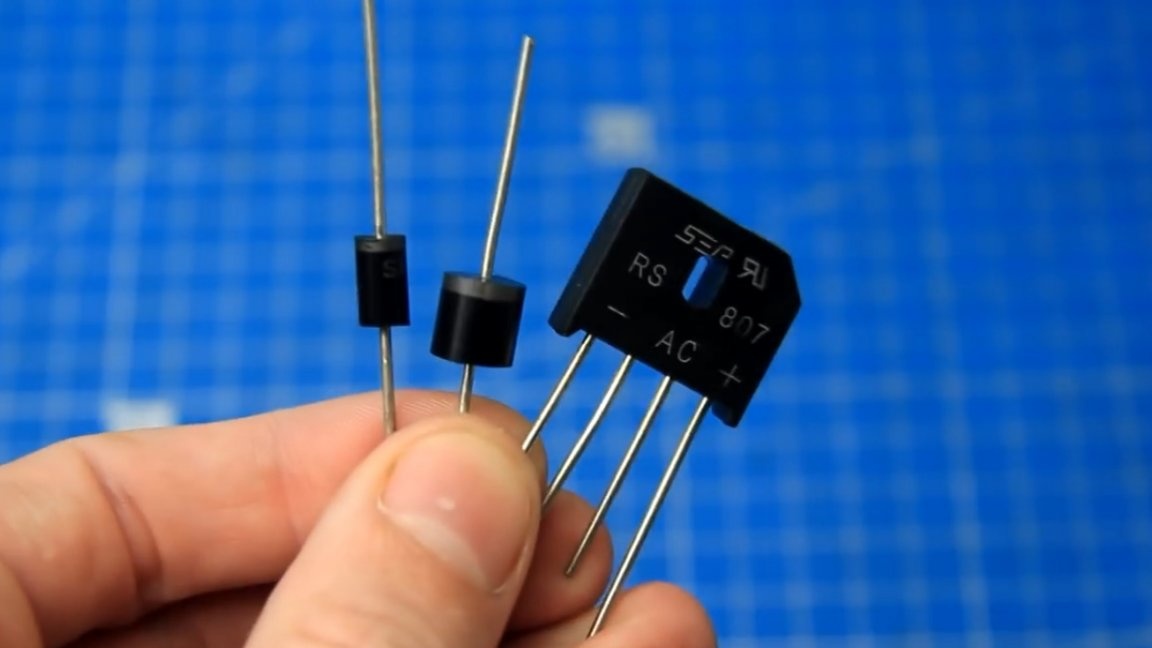
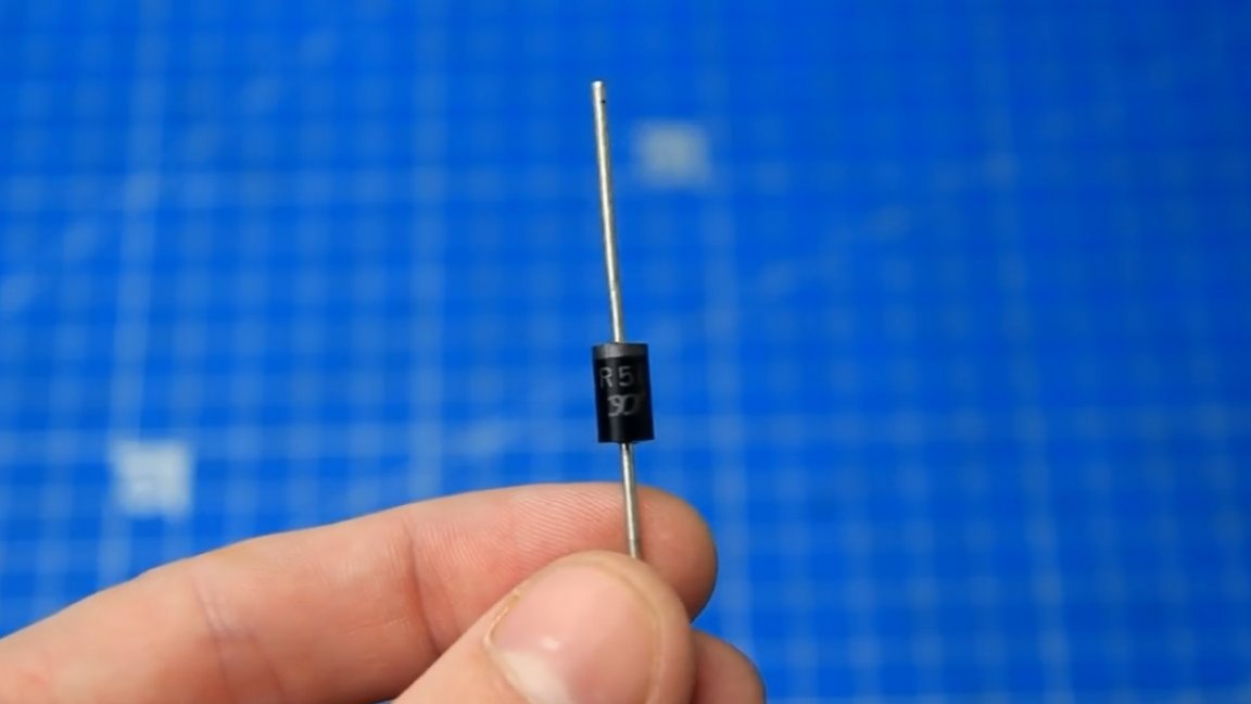
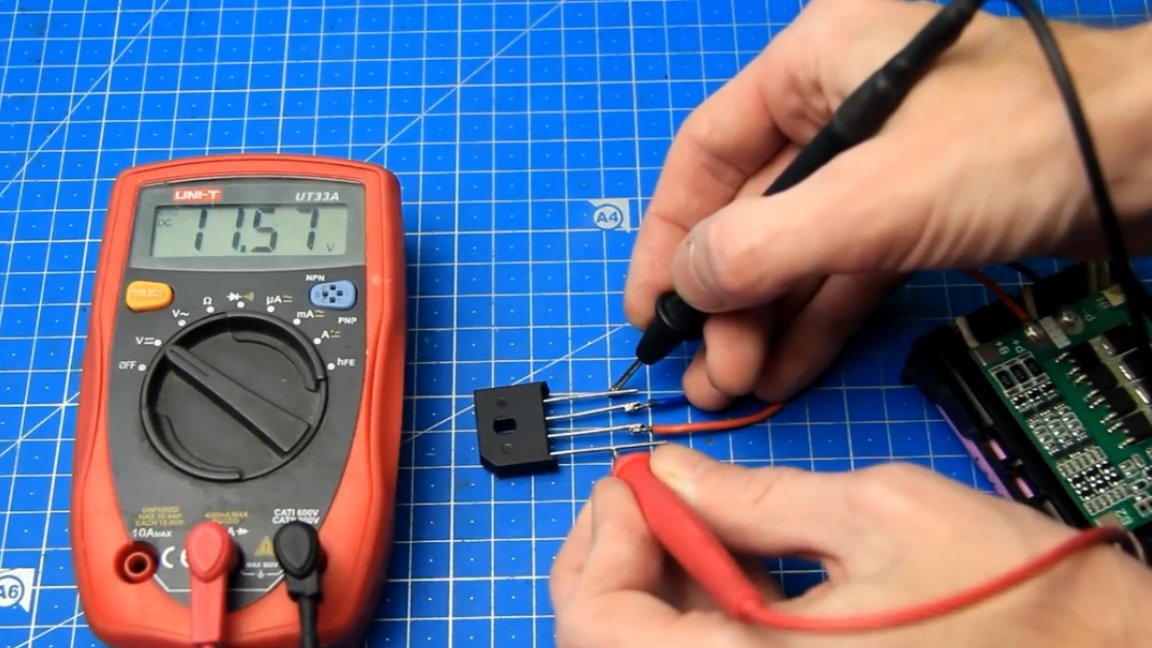
Here is a comparison of the voltage drop across a conventional diode:
As you can see, it is about 0.4V. On the Schottky diode, the voltage drop is already lower and amounts to 0.2V.
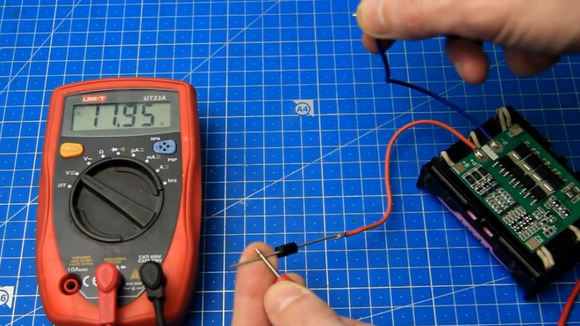
The voltage drop across the diode bridge is the largest and is 0.6V.
During loading, voltage drops may be slightly higher. In fact, it is not often possible to confuse the polarity of the supply, but the loss in the presence of a drop on the diodes or diode bridge will be constant and as a result there will be heating, which in turn leads to the need for cooling. As you can see, diodes can be used as protection against reverse polarity, they work, but you still want better protection so that there is no heating, losses are minimal, and good operating currents.
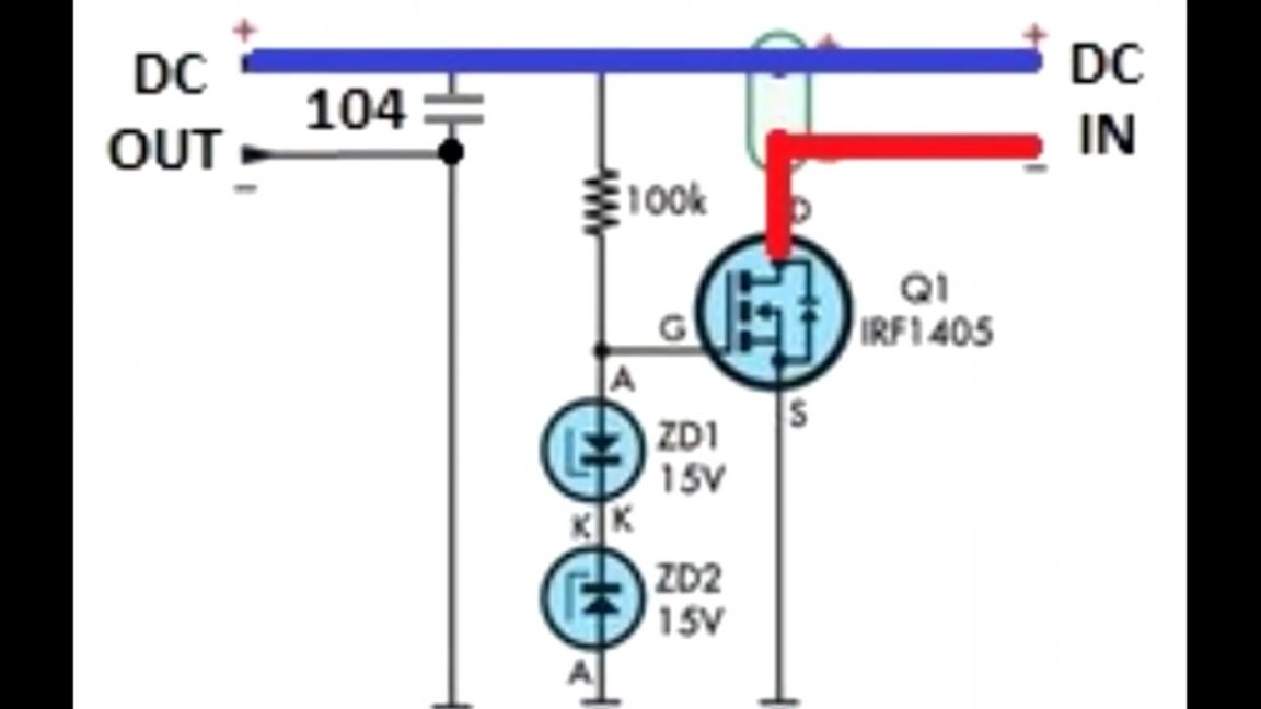
The author offers one simple, but rather good protection scheme against polarity reversal in power supply with a powerful field-effect transistor.
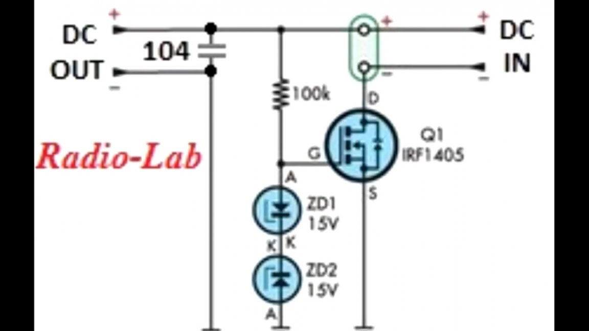
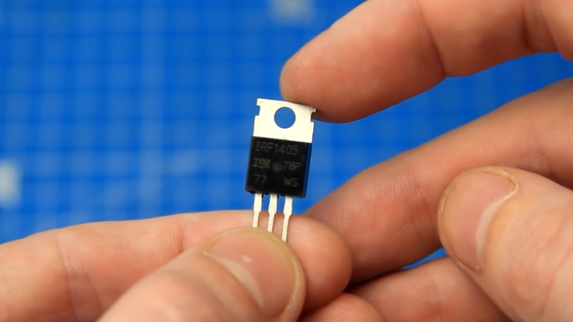
This circuit is suitable for protecting devices with unipolar power. Power Field Effect Transistor - IRF1405 is a powerful N-channel.

Such a transistor is capable of switching a sufficiently large current and, in turn, has a rather small resistance, due to which there will be practically no voltage drop, and, therefore, there will be almost no heating, or it will be minimal, there will be no such losses as on diodes.
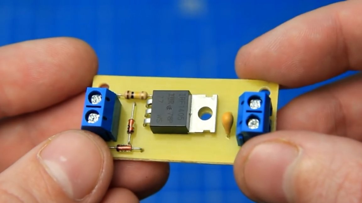
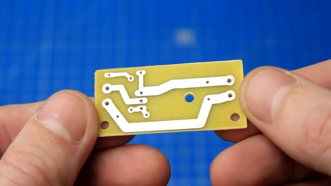
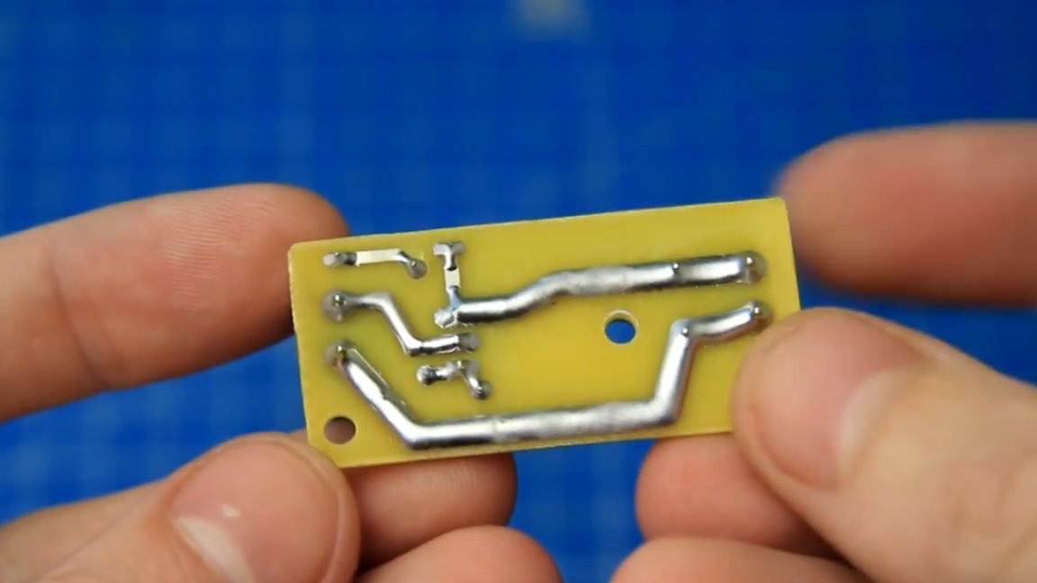
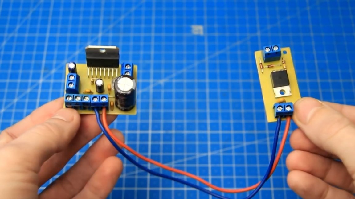
The author drew such a miniature scarf for this protection scheme.
The operation of the circuit is extremely simple: if everything is correctly connected, the transistor is open, and the current passes through the transistor.
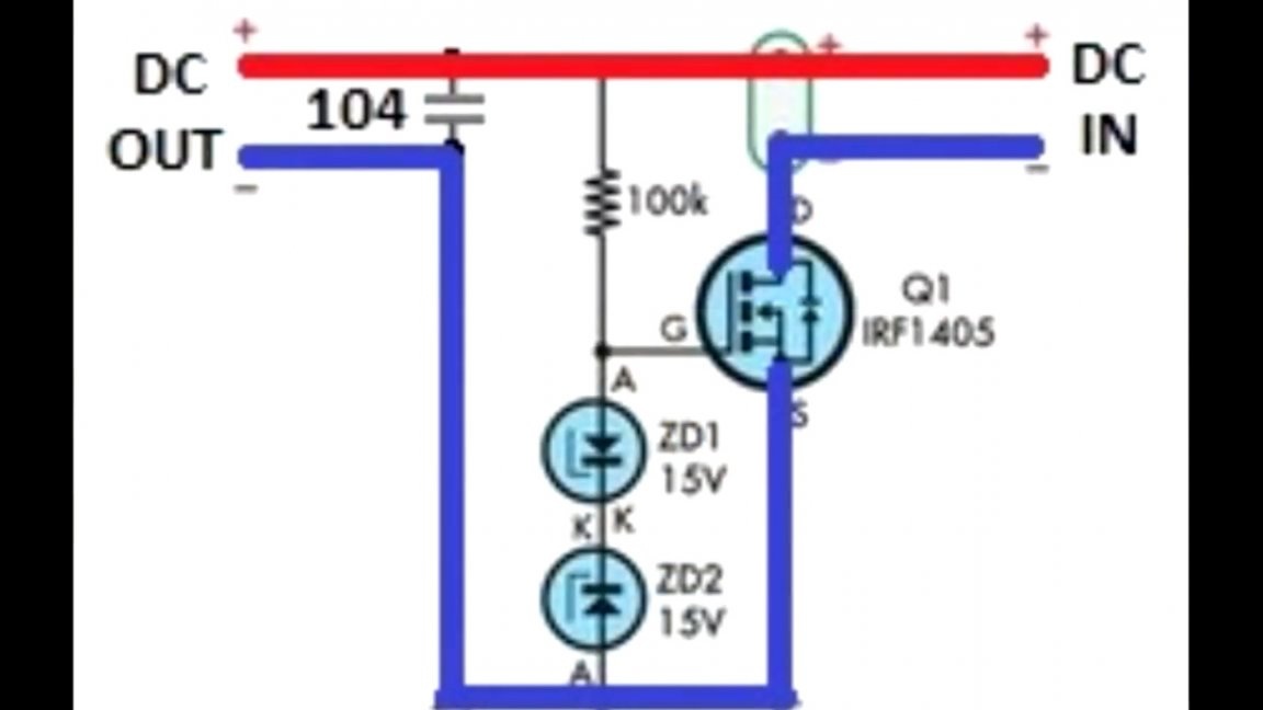
If the polarity of the power supply is not connected correctly, the transistor closes, thereby creating a gap in the power circuit and the entangled plus does not pass further than the transistor.
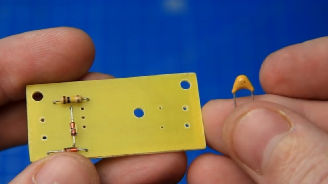
On the radio market, all the necessary parts for the assembly of the protection board were purchased.
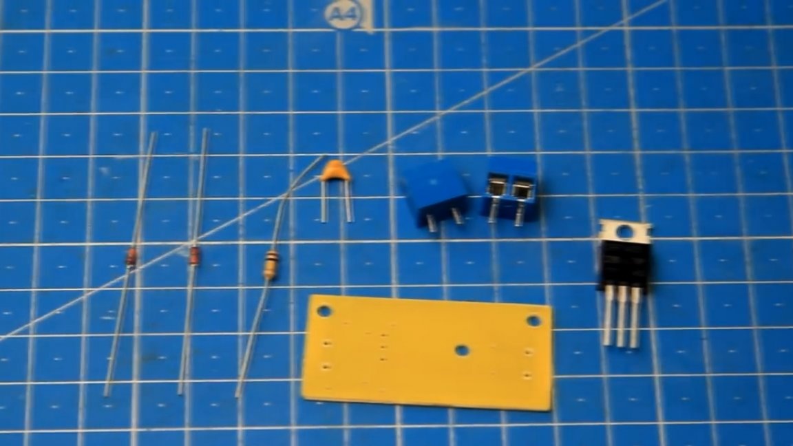
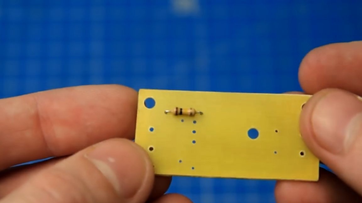
First of all, the author installs a 100kΩ resistor in place and solders it.
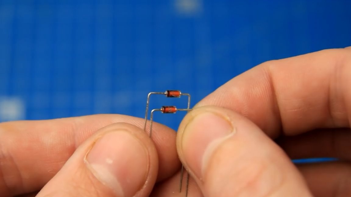
Next, we will install zener diodes on 15V 0.5W, be sure to observe the polarity according to the marks of the cathodes.
Next, install a non-polar capacitor with a capacity of 0.1 μF.
Now terminal blocks for input and output power.
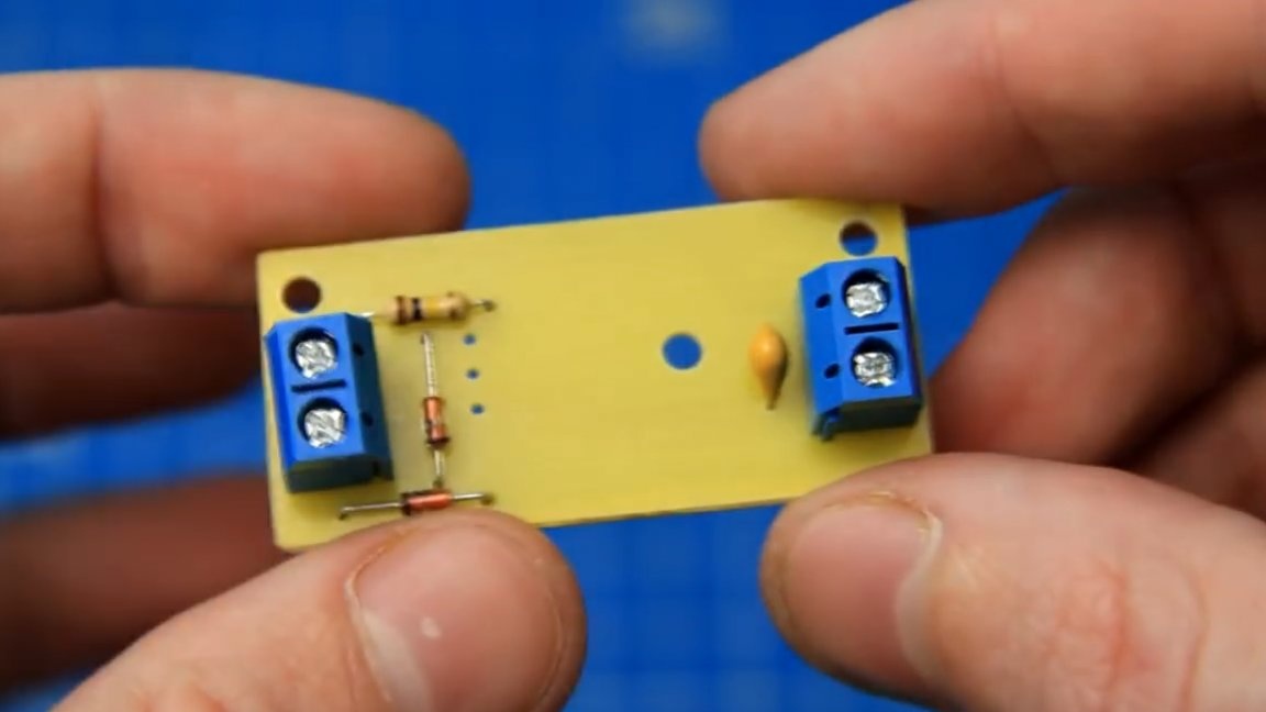
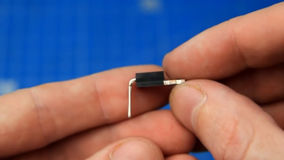
The board is almost ready, there is only one element left - a power transistor. To install it, the author bent the legs of the transistor - like this:
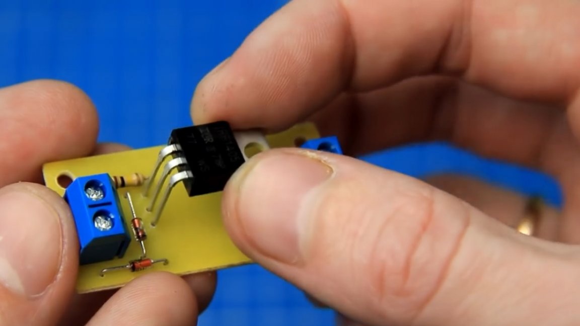
And set it in its place. The result is such a small and convenient power protection reverse polarity protection board for amplifiers and devices with unipolar power supply. Unipolar power is where there are two power wires: plus and minus.
After the end of soldering, the circuit board must be washed with flux residues, so that everything is clean and beautiful.
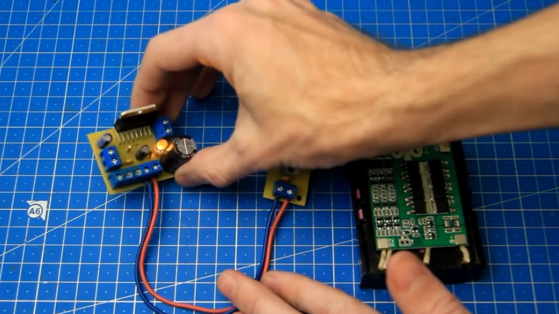
Now let's check the functionality of the protection board we have assembled. To test the board, we connect a battery with a power supply voltage of 12.1V to its input. The author connected the multimeter probes to the output of the board. First, we connect the battery correctly, observing the polarity.
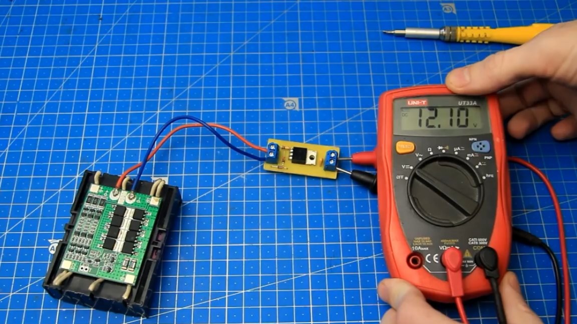
As you can see, there is voltage at the output of the board, and the voltage drop is so low that the multimeter does not notice it.
Now we change the polarity of the power and connect the battery, confusing the plus with the minus.
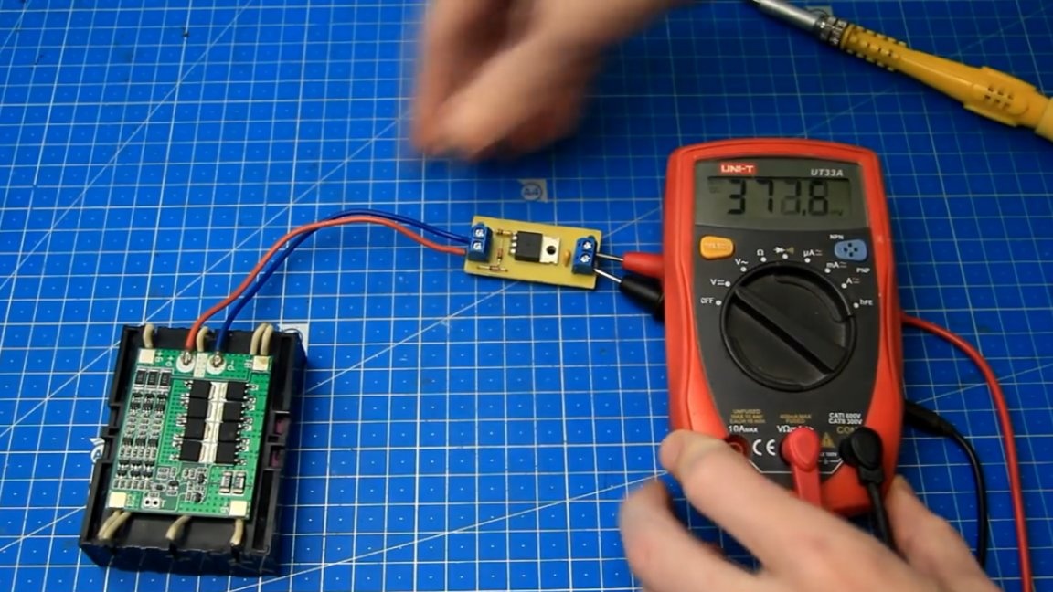
As you can see, the transistor is closed, the protection board has worked and does not pass anything, thereby protecting the device (in this example, a multimeter) from reverse polarity. If you reconnect the power correctly, the transistor will open and the battery voltage will appear at the output of the board. Great, the board is working.
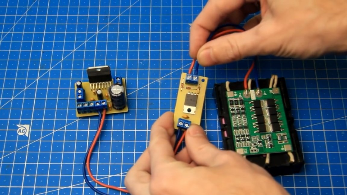
After we tested the homemade board and made sure that it works, you can connect the protection board to the sound amplifier. We will use the simplest amplifier on the TDA7377 chip without any protection against reverse polarity, and if the power polarity is confused, then at least the polar capacitor in power will explode and the chip will burn.
The protection board is connected to the gap of the plus and minus power supply of the amplifier, on which there is a possibility of polarity reversal. We must connect the power wires coming from the protection board to the amplifier board observing the polarity.
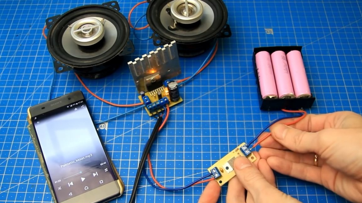
That's it, now our amplifier has protection, and the polarity reversal is not afraid of him. We connect the power correctly.
As you can see, the LED on the amplifier lights up, everything is fine, the amplifier has power. And now, we connect the power by reversing the polarity.
As you can see, nothing is smoking and the LED on the amplifier board does not light, therefore, the amplifier does not receive power, which means that our home-made protection board is working and fully fulfills its task.
This board can be used to protect against reversal of sound amplifiers with unipolar power, including class D amplifiers too, portable speakers and many other devices. Remember, if there is at least the slightest chance of reversing the polarity of the power supply, then at the right time, at least, protection from reverse polarity will save you money and protect your product from accidental reverse polarity and as a result of breakage.
It is also important to understand that in some cases it is more convenient to use diodes or a diode bridge as protection against reverse polarity, and in others it is necessary to look at the assembled protection board for tasks. Try, collect and repeat. Archive with the board can be downloaded HERE.
Thank you for attention. See you soon!
Video: