

I'll tell you about my homemade.
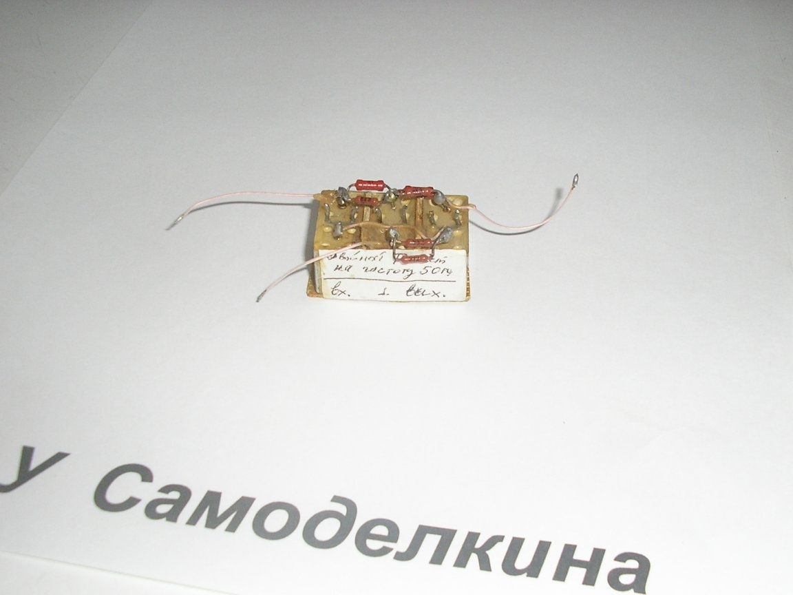
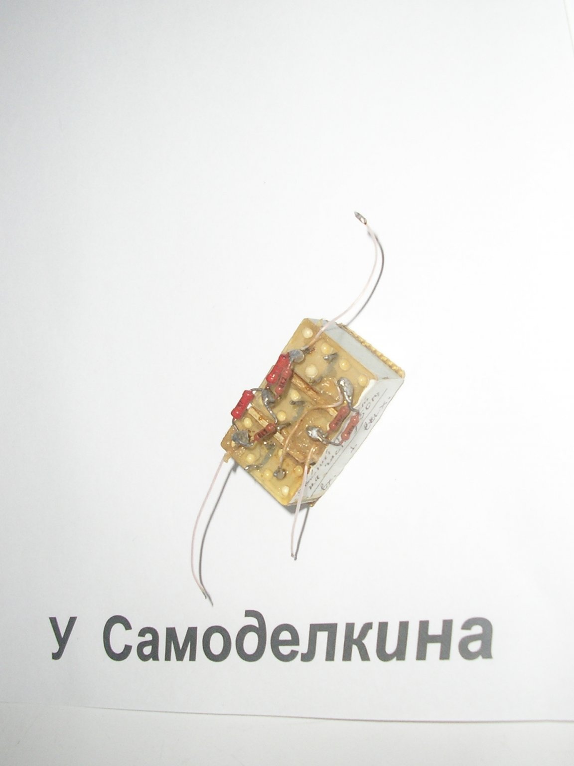
This is a 50 Hz mains filter.
How can it be useful.
Anyone who is involved in amplifiers, sound and measuring equipment, knows what the background of alternating current. Getting rid of it can be difficult.
As a basis, I took the double T bridge.
The principle of its operation and calculation of elements is quite complicated.
This is described in various sources, you can read if you wish.
With fine tuning, it can greatly weaken the noise, and also not introduce noise, since there are no semiconductors (transistors) in its circuit.
And does not require a power source. It has small dimensions.
This is a schematic diagram.
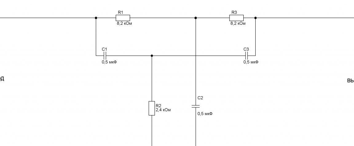
I pointed to homemade entry and exit. Although I suppose that they are reversible, I did not check, there was no need.
The following details were used:
Three identical capacitors KMBP and six resistors MLT 0.125 watts. In the diagram, I showed only three resistors, and six in the photo. This is due to the fact that I did not have exact values and had to be selected using a digital multimeter by parallel connection.
Materials:
Solder, a small piece of unfolded textolite, some glue and a mounting wire and solder.
Instruments:
Soldering iron, wire cutters, scissors, tweezers and a scalpel.
When repeating the design, the following should be considered.
Capacitors can be taken KMPB, MBM and others, except ceramic and oxide (electrolytic). These types have a strong temperature dependence of capacity.
If possible, select the ratings of the parts using a digital instrument. From the selection accuracy depends on the suppression quality of the network pick-up of 50 Hz.
Or look at the percentage accuracy of the part rating. +/- 5% already gives good noise reduction quality.
On the graph, I showed the frequency response of the device. Of course, in practice it is somewhat smoother.
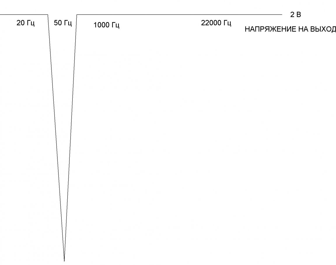
In conclusion, I will add. By changing the ratings of the parts, the filter can be made to suppress interference of a different frequency.
Sincerely, author.