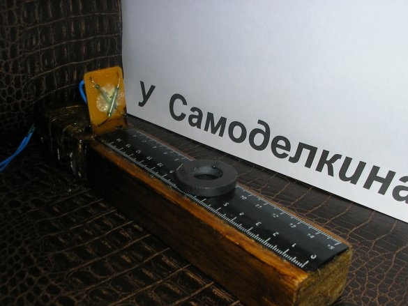
» Fixtures "The prefix" Tester of magnets "

The prefix "Tester of magnets"

Hello, dear authors, journalists, readers!

This prefix to the multimeter allows you to determine and compare the strength of magnets, the direction of the magnetic field and the shielding (anti-magnetic) effect of various materials.

Applied Tools:

Wood hacksaw
Hacksaw
Drill with a drill with a diameter of 1 mm
Flat file
The file is flat
Nippers
Pliers
Round pliers
Ruler
Marker
Soldering Iron 25 W
Scissors
Sandpaper
Brush

Materials:

Pine beam
Fiberglass
Scotch
Glue
Solder
Rosin
Solvent 646
Rags
Stranded wire
Reed switches
Plastic line

I used a magnetically controlled sealed contact (reed switch) as a magnetic field sensor, and a multimeter as an indicator.

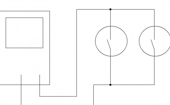
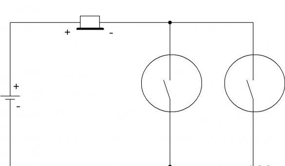
Is that simple? Let's take a closer look at my homemade. Here is her schematic diagram.

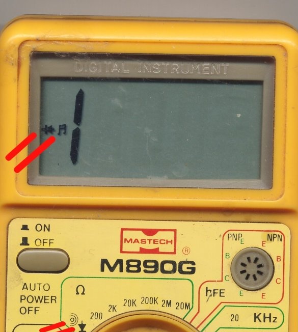
Two parallel-connected reed switches are connected to a multimeter turned on in semiconductor continuity mode.

This mode can be found even in the most inexpensive multimeters. In this mode, the device gives a sound signal at a low resistance of the measured circuit, of course, and when it is closed.

The reed switch used in this homemade product has a normally open contact. This means that the contact is open in the absence of a magnetic field. When the field appears, the contact closes.

Why did I use two reed switches and not one? The fact is that the reed switch, due to its design features, reacts to the magnetic field differently from different directions. Good, the more reed switches connected in parallel, the better. But, guided by my experience with magnetically controlled contacts and the principle of reasonable sufficiency, I settled on two, placing them in a special way.

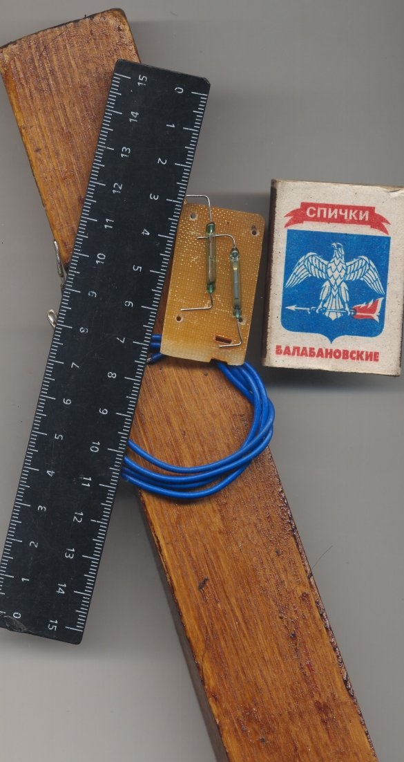
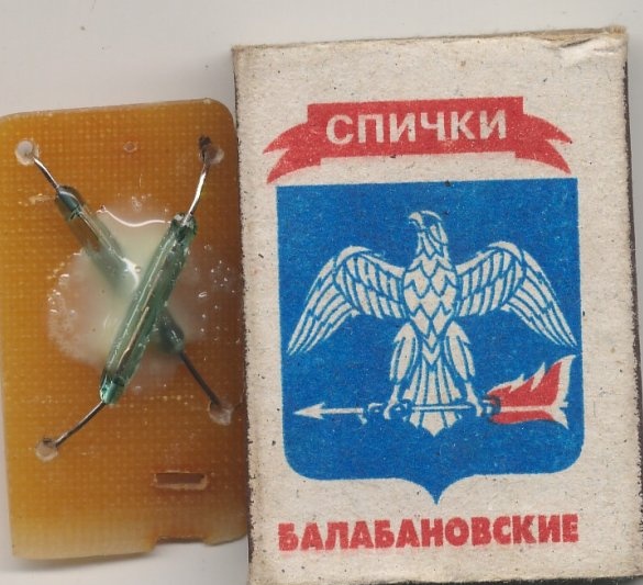
This photo shows the details from which I assembled this homemade product. There are very few of them.

Two identical reed switches from burglar alarm sensors, a board, a ruler, wires, a piece of fiberglass.

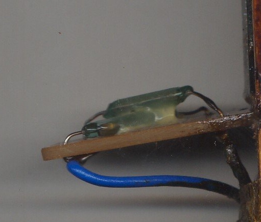
I placed the reed switches one above the other in the form of the letter X. With this arrangement, when one reed switch stops responding to a magnetic field of a certain direction, the other reed switch starts to respond.

To do this, I cut a small piece of fiberglass, marked out and drilled holes. I inserted the reed switch legs into the holes, bent them on the back of the fiberglass. Glued.

The photo shows that the installation of the reed switches, when bending the terminals, broke off part of the glass case of one of them. However, I checked the serviceability of the reed switch and continued to work. I soldered the reed contacts and the output wires of the console.


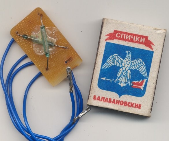
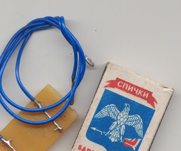
I made the ends of the wires in the form of tinned loops, since my multimeter can use crocodile clips on the probes.

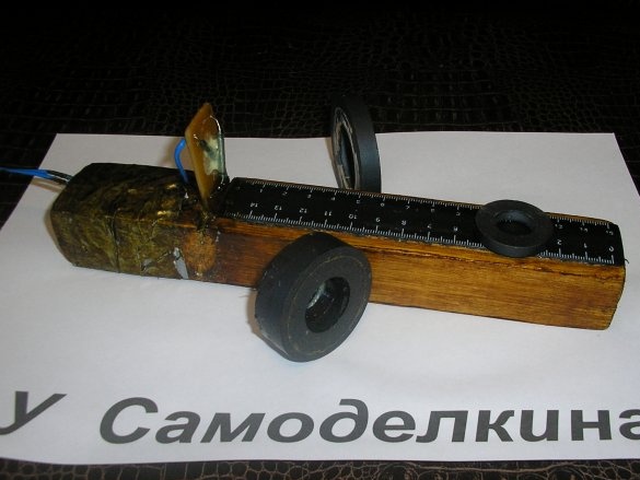
I inserted a board with reed switches in a slot made in advance in the board - at the base, adding a little glue for reliability.
The prefix

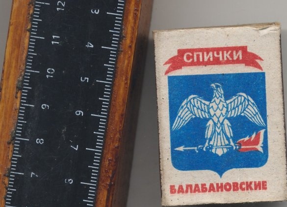
I glued the ruler.

Fastened the wires with tape.

The prefix is ​​ready.

A small addition. Assembled this design as follows.

I took a pine beam suitable for the width for the manufacture of the base.
I tried on it a ruler, which in the design serves to determine the distance to the magnet under study.
I figured out how much space is needed to fix the board with reed switches and fasten the wires.

Summarized, gave a margin up, marked out and sawed off the desired piece of timber with a hacksaw on a tree.
He made a transverse cut in the timber with a hacksaw and a flat file to install a board with reed switches.
I used a hacksaw to cut a piece of fiberglass that was necessary in size. Marked and drilled four holes in it for the conclusions of the reed switches.

I filed the edges of the bar, cleaned it with sandpaper and covered the bar with dark lacquer for refinement.
Measured two pieces of a multicore installation wire. In the end he stripped the insulation and tinned.
The rest is described above.

Now that the prefix can and how to work with it.

Turn on the multimeter in semiconductor dialing mode. The magnet under investigation is slowly brought closer to the circuit board with reed switches until a sound signal appears. We read the distance to the magnet on a scale (ruler). We write the result in a notebook. We take the magnet back until the sound signal disappears. Expand the magnet on the other side. Repeat the operation as the magnet approaches. We write in the notebook a new result. Similarly, we obtain a lot of data on the effect of a magnet on an object, depending on the position of the magnet relative to a stationary object. Difficult, huh? But it’s clear.

Next, take another magnet and repeat these operations. Now we have the opportunity to compare two magnets in the same conditions.

Now we examine the antimagnetic properties of materials, how much they weaken the effect of the magnetic field. To do this, take any magnet, preferably more powerful. According to the method described above, we determine and record the distance to the magnet at which the signal begins to sound. Without changing the position of the magnet, we remove it on a scale - a ruler until the signal stops. Immediately in front of the reed switches we place the investigated antimagnetic material. The area of ​​the material sample should be such as to completely close the reed switches from the magnet. Zoom in the magnet. When a beep appears, stop. We read and write the result. The distance (result) should decrease. From this we conclude how much this material weakens the magnetic field. This is similar to how materials attenuate radioactive radiation. It was very interesting to compare the properties of tin, brass, permalloy tape, transformer screens and more. Now think about why I used wood for the base of the console, and a plastic ruler for the scale.

Recently, I was engaged in research work "on the influence of a magnetic field on water meters." Thanks to this prefix, I was able to explain the “phenomenon”, why the vaunted neodymium magnet cannot stop some counters, and the usual, ferrite magnet, from the speaker, can.

You can make not a prefix, but a functionally complete device. In this case, you can replace the multimeter with just two parts. Battery and "tweeter" with a built-in generator, collecting such a circuit.

A power switch is not required; in the absence of a magnetic field, the circuit consumes nothing.

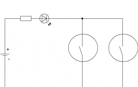
Or by replacing the multimeter with three parts. Battery, resistor and LED, as in the diagram.

A power switch is also not required, in the absence of a magnetic field, the circuit consumes nothing.

In conclusion, I want to add.Magnets, if they are large, can be approximated from the sides of the console, also read the result on a ruler. For this reason, I took a block as a basis, not a flat board. The ruler has a scale on both sides, which makes it convenient to work with different positions of the console relative to the experimenter.

I hope this article was interesting and useful to you.

I will be glad to your comments and suggestions.

Sincerely, author.
9.7
9.3
7.7

Add a comment

    • smilesmilesxaxaokdontknowyahoonea
      bossscratchfoolyesyes-yesaggressivesecret
      sorrydancedance2dance3pardonhelpdrinks
      stopfriendsgoodgoodgoodwhistleswoontongue
      smokeclappingcraydeclarederisivedon-t_mentiondownload
      heatirefullaugh1mdameetingmoskingnegative
      not_ipopcornpunishreadscarescaressearch
      tauntthank_youthisto_clueumnikacuteagree
      badbeeeblack_eyeblum3blushboastboredom
      censoredpleasantrysecret2threatenvictoryyusun_bespectacled
      shokrespektlolprevedwelcomekrutoyya_za
      ya_dobryihelperne_huliganne_othodifludbanclose
155 comments
Author
Understood thanks.
Author
This is a valid universal device, until it was assembled into a case and sold.

What do we see?

I applied a highly sensitive sensor - a ****** sensor of a magnetic field on the Hall effect of foreign production. Its main characteristics. The detection threshold of the magnetic field is 4 mT. Triggers and releases abruptly (Schmitt trigger). Open collector output. The supply voltage is 4.5 ..... 24 V. In this range, all characteristics are preserved - there is a built-in power regulator. The output holds a current of up to 25 milliamps, so without hesitation I slammed the LEDs into it. The output state is fixed when the threshold is reached and changes only when the magnetic field vector changes.

The sensor has a high resolution. It can track the tilt or rotation of the magnet relative to it in just a few degrees.

When choosing a power source for this design, I settled on a 9 Volt Krona battery. The current consumption of the device is small, only 3.5 mA, so this battery is enough for a long time. I didn’t forget to put the power switch and the diode protection against overturning.

The device helps to compare magnets by the strength of their magnetic induction. Since the threshold of the sensor is known and does not change, it is possible to calculate its magnetic induction by the distance to the magnet, using a simple calculation.

The device allows you to determine the poles of the magnets. To do this, I connected in a special circuit 2 identical red LEDs to the output of the microcircuit - the sensor. I designated LEDs C and S (North and South). When you bring the magnet to the sensor, one or the other LED lights up, showing which pole is brought up. Both cannot catch fire at the same time. Ambiguity is excluded.

Already tried different magnets, which were at hand. Reached the detection range of 10 centimeters, as writes Pronin about the sensitivity of Hall sensors.

I connected a frequency meter in the mode of measuring the frequency and pulse counting. It works great. It is possible to do tachometers and counters of the number of turns in winding machines on this principle. In this case, a small magnet is glued to the shaft or pulley, gear and when traveling past the sensor forms a clear impulse with steep fronts and without bounce, as, for example, with reed switches. These pulses are then fed to a frequency meter or multimeter included in the frequency measurement mode.

I have photos and video tests. Already there are people who want to buy this homemade product. I will sell it. I will publish the homemade product on the site, I will attach both the circuit diagram and a detailed description. Surely, many will draw from the article a lot of useful things. Someone just copy. I will not mind.

Ivan_Pokhmelev and Korolev, do you mind reading, discussing, criticizing and praising?

However, the latter does not belong to Korolev, I have never seen him praise anyone (on the site) xaxa
Create a theme, you can upload a file up to 6 meters, in the archive 29 meters. Well, more on Google disk, YouTube or any file hosting service.

In kamenty restrictions 1.36 mb
Author
I was just about to upload my interesting video of testing a homemade magnetometer, and here it’s such a bummer. They write that it can only be downloaded from YouTube. But what, its impossible, or what? Can someone tell me how to do this? Just do not send me to the admin. I don’t want to disturb him in every garbage. He has enough trouble already. File information. Mov videos. The size is about 5 megs.
Thanks to the one who will prompt.
Author
I’ll show you a video about testing the assembled magnetometer, until I sold it. An alternative worker presses one, faster, says, cram into the case, buy even with imperfections. He collects another magnetic motor xaxa
And like, guys, gravity works ... It's just that nothing is attracted to our world, there is no such phenomenon. There is a zone of high pressure and low, that's all, there is only pressure and its absence - "0".
R555
In milesTeslach
Tesla (Russian designation: T; international designation: T) - magnetic field induction unit in the International System of Units (SI), which is equal to the induction of such a uniform magnetic field in which 1 meter acts on a force of 1 ampere per 1 meter of the length of the direct conductor, which is perpendicular to the magnetic induction vector
smile
Author
In miles Tesla. Priborchik for more serious than you think. The batteries for the camera just recharged. Now take off and show. But not very much.

That's when I publish this homemade product, then you will know everything. Almost all. xaxa

They ask me to quickly assemble in the case. They want to buy.
R555
weak, ferrite magnet ... No, ferritic, it turned out to be 2 times stronger
And in what units, in fact, do you measure the strength (weakness) of a magnet? scratch
and magnet - a moving charged body? Nonsense. a universal magnetic field moves, and a magnet is just a piece of pipe that is correctly bent and set direction by a powerful electromagnetic field.
And at the expense of matter is interesting, I support

Dmitrij
It really smells like levitation and exposure to unknown forces.
the magnetic field is material, i.e. exists regardless of our knowledge of him; It is generated only by a moving electric charge: there is a magnetic field around any moving charged body. A magnetic field can also be created by a magnet, but even there the cause of the appearance of the field is the movement of electrons. A magnetic field can also be created by an alternating electric field;
Magnetic field (MP) is a special type of matter through which the interaction between moving charged particles
The doctrine of electromagnetism is based on two points:
a magnetic field acts on moving charges and currents;
A magnetic field arises around currents and moving charges.
smile
Knowing this, we will again draw an analogy with pipes.


Now estimate that the pipes are under water, as a result there will be no pressure between them, but the pressure will be from both ends of the pipes, which will shift the pipes to one another.
But from the rarefaction side the pipe will be pushed weaker than from the pressure side, as a result, beckons with a plus should be attracted more than a minus, or vice versa. But this is a completely different story)))

But our magnets are not under water, and a magnetic field is not a stream of water. But there is definitely some kind of energy or magnetic environment in which we live

And, by the way, unidirectional fields are repelled by the fact that they reinforce each other, as a result, the magnet has enough strength to "push universal magnetism."
And I seem to understand. Magnetic fields in a piece of iron are scattered randomly, therefore it does not attract a nikher to itself. We bring the magnet, it neutralizes the opposite fields, as a result, the piece of iron turns into a magnet with one pole, which is attracted to the ferromagnet.

But stop, why is the iron magnet attracted to the magnet? Only “negative” poles or only “positive” ones will remain in the piece of iron, depending on which pole to bring the magnet to. The "minus" of the magnet will kill the "pluses" and the minuses will remain in the piece of iron, which we all refer to the fields of the magnet, but not))

But then again, what presses a piece of iron to a magnet and a magnet to a piece of iron? On the back of the magnet there will be a reverse pole (plus type). The magnetic fields are circular, theoretically they can, but no, they are, they go in from the back and "press" on the piece of iron.

But no, I understand !!!))

We bring the magnet to the piece of iron, it kills domains with a "negative" magnetic field. On the reverse side of the piece of iron, the "reverse" magnetic field "-" enters, which kills domains with a "negative" field. But! The strength of the magnetic fields will be different, the "bypass fields" ("-") will be weak, so there is a "potential difference" in neutralizing the magnetic fields in the piece of iron, and as a result, it presses it to the magnet.

But that's why it presses, it’s already very interesting. It really smells like levitation and exposure to unknown forces. Some external energy presses on the "unbalanced" piece of iron, it works like resistance in a certain flow of energy (unknown).

P.S. Yes, I drank a lot of coffee.
Smacks of Levitism-)))
The magnet does not have poles; there are directions of magnetic fields whose shape depends on the shape of the ferromagnet. secret2
Unidirectional fields repel, and multidirectional fields attract. secret2

And then I got philosophical thoughts ...

Imagine two pipes with a stream of water, if you direct one stream opposite the other, the pipes will repel. These are unidirectional fields of a magnet.

But the reverse analogy is already causing philosophical interest. One pipe delivers water under pressure, and the other opposite it absorbs this water. But by analogy with magnets, they will not be attracted, streams neutralize each other. We lower jet thrust and rarefaction, because the magnetic field is "standing".

And then it’s interesting that the pipes “attracted”, something should push them, squeeze from the back. But what if the same thing happens with magnets? "Different poles" simply neutralize each other, and magnets are attracted due to the imbalance of magnetic forces, they are pressed outside dontknow search meeting

We must try to shield the external magnetic field and see if the magnets will be attracted in this case and with what force. And they will be attracted weaker or not at all (according to experiments in my imaginary laboratory)

And even more interesting, if you take a magnet and a piece of iron. The piece of iron logically neutralizes the magnetic field, but then what kind of force presses the magnet to the piece of iron or vice versa? dontknow
Author
Here I show how a highly sensitive Hall effect sensor, which I used in my multifunction device, detects the competition of an ordinary, weak, ferrite magnet from a security alarm sensor with a strong neodymium magnet from a CD drive.

I separated them with a matchbox so that they would not stick together. It can be seen that they rushed to each other.

What do you think, who won by the strength of the magnetic field on a nearby object? Of course, neodymium!

No, ferritic, he was 2 times stronger. boss What can this homemade appliance, I will briefly tell you soon. Photos will be. More precisely will be. One thing. xaxa

Regards, R555
Author
That's right, it turns south to the north. So in my photo the arrow turned around to the north pole of the magnet. The circuit has already been assembled and successfully tested. Now I take a picture and prepare a short description, otherwise it will not be clear to everyone. Look at the site, see what I get, you won’t regret it.

Most likely, this is the last preview of this new author’s homemade product of mine. I already have several people who want to buy this device or take it for a while.
Ivan Pokhmelev chewed everything, had not yet given a link to the Internet. There are even more for different contingents yes
And the question (suggestive) is correct - hde Sensor magnet tested in the photo? Specifically!
I looked on the Internet about the definition of poles in magnets. (I do not respect YouTube! With prokhindeyami). But, having thrown off the husk of various sizes, I saw an interesting definition - a piece of polystyrene in a bowl with water and a magnet on it ... It turns to the North with the south pole! Where do we know the North Star ... Here's a compass
Author
And what about the sensor? I asked if I marked the poles of the test magnet correctly. Isn't it right that the compass needle points to the north pole of the magnet? When using a compass, what do you have an arrow pointing to the South or something?

I put an exclamation point near the steel bracket on the strap that the fools who made the compass put on. The main thing, the buckle was made of non-magnetic material, but they did not think about the bracket. xaxa

I already ate this bracket with powerful nippers and threw it in the trash. Now the compass began to show more accurately to the North. boss

I recommend everyone to check their compasses for similar magnetic materials on the strap.

I repeat my question again. Am I correctly marking the poles of the test magnet? Campaign, I'm not a fool at all yahoo xaxa
To the north shows the south pole of the compass needle.
But nothing is clear from the second photo: where is the sensor, what is the exclamation mark? ((
Author
Now I’m finishing my homemade work on the basis of a magnetically sensitive microcircuit. It turns out not a bad magnetometer, the threshold for its operation (* mT) is already known, a secret. Tachometer. Rev counter (suitable for winding machines). Magnet tester (determination of their magnetic induction and magnetic field direction). And many other features. And all in one device. good

I urgently needed a test magnet with a reliable pole position. Where to run, where to buy? I decided to quickly make a magnet from the security sensor IO 102 16/2.

For the exact definition of the poles decided to use a conventional compass.

Tell me, did I mark the poles of a magnet or a fool correctly? xaxa xaxa xaxa
Author
Ivan_Pokhmelev ! Victory ! Urrra! I managed ! yahoo
Here is a photo of the actual experimental design.


Next, first of all, I will connect a two-color LED - it will show the poles of the magnet! Already managed to connect an electronically counting frequency meter and a multimeter in the frequency meter mode. Got a digital tachometer of 5 parts! Checked like that. A tiny magnet was glued to the drill chuck (so as not to be discarded by centrifugal force). He brought it closer to the chip, turned it on. It works great! Shows the number of revolutions per second and does not need to adjust anything in the circuit. Well, counting into revolutions per minute is simple. Multiply by 60.

And the compilers of the datasheet are bastards. ireful They painted the pinout incorrectly (mirror). But the head did not check. The error spread throughout the world. Therefore, it didn’t work right away. That's how to believe the directories. I must believe my notebooks! Well, you get the point. xaxa I guessed it, unsoldered the microcircuit, turned it on the other side and soldered it. Turned on, it worked. Surprisingly, ms did not burn out. good

Now I’ll give up, I will fill up with consoles and functionally finished products. dance3

I'll get drunk on joys! Joke.
It did not occur to them that this is a very important parameter for some applications.
Not. The point is not what might come to mind there.
It's just that this parameter has a large spread, so it is impossible to reliably normalize it.
Author
So this morning I have already soldered a “fly” of only 3 details. The LED, resistor, and high-sensitivity sensor are Hall effect sensors. I got 2 identical sensors (popped out of the trash). I tried, the LED is lit weakly constantly. But this did not upset me much. It will be necessary to change the AL307 to the mnemonic, as they are there, instrumentation .. I recall now or to the ultra-bright white with a diameter of 5 mm, I have them, I just need to find them. And in my notebook I saw the test results, at what current they begin to glow.20 μA total !!! Even manufacturers in their datasheets do not provide such data. It did not occur to them that this is a very important parameter for some applications. If this succeeds, I will immediately collect the simplest magnetometer, the simplest armature finder in the slabs and much more. I’m not just developing this topic. A metal detector based on a reed switch is already ready !!!
It was determined that the Hall sensors are weakly sensitive, for large magnetic fields.
You can make a magnetometer (simpler) that will feel (qualify) different magnets at a distance of ~ 10cm. On operational amplifier
Author
In fact, I called the crap not the BB engine, but the 8220 videophone where this engine stood.
The fact is that entire batches of these devices with filthy property came across. Let the owner of such a VCR look at the cassette; after looking, he returns it with snow in the image. At that time, they did not understand what it was connected with. One thing is clear. Something rubbed the tape after passing through the disc BVG. Right now this tape drive lies in front of me. I see a lot of interesting things that could overwrite. A bunch of racks - guides and a block of heads (universal sound and timing). And washing for these tracks is also in this block. In general, the Japanese fellows, they came up with this way of recording color video, and even the sound on a tape moving at the same speed as in a conventional audio tape recorder. They came up with a way to tilt / line video recording. It is written not along the length of the tape, but almost across. JVC Patent good
And I come to the conclusion that the magnet on the rotor of the engine magnetized the capstan. He wiped the tape after watching the film, at the exit, so to speak.

It is strange that only in certain batches of these vidak. dontknow
Author
Finally, I found in my stocks an engine BB (drive shaft) from the SAMSUNG VIDAK EPECRONICA VMC 8220.

This dvigun disassembled pretty quickly, without cutting with a hacksaw.
In total - he simply unscrewed several screws and nuts, removed several levers from the LPM plate. After removed the lock washer from the shaft. He pulled the shaft along with the rotor - a multi-pole magnet from the bearing. Then he separated the engine from the tape drive. And I realized that it was not in vain that he was busy. That's what I need.
The first thing I noticed was that the Koreans wound as many as 24 (!!!) coils in their three-phase motor, versus 9 in three-phase coils from the sidyuk, which I dismantled earlier with attempts. But, in general, I don’t need a stator, I will throw it in the garbage chute. xaxa
But I need the board itself. With a rectangle I designated a highly sensitive sensor - a Hall effect sensor.

On the other side of the board are 3 Hall sensors without any signal processing. The main thing is that these devices are not very small, and it will not be difficult for me to solder thin wires to them.
And based on this shit, I can now make some very simple, interesting and useful homemade products. It:
Magnetic field detector.
Metal detector (it is convenient to search for reinforcement in plates so as not to be buried by a drill))).
Other.
Author
I want to give useful advice to those who independently mount a security alarm for the first time. If you put door opening sensors based on a reed switch and a magnet on an iron door, be sure to place one or more plates of some non-magnetic material (plastic, plywood, aluminum) under the reed switch and magnet. The quickest way, so as not to saw anything, not to drill, is to disassemble the second set of the sensor and take the halves of the cases from there.
Author
And here is another interesting application of reed switch. Security sensors DIMK. I was surprised to learn that they are still being produced. Price 118 rub.

These sensors can be used as a glass break detector (and attempts to break). As a detector for opening the cellar, manhole cover. The principle of his work is as follows. In guard mode, a loosely suspended brass plate of a special shape with a magnet on it is located next to the reed switch. Its contacts are closed and pass the current of the control panel loop (receiving - control device).When changing the position of the sensor or hitting the glass, to which it is glued, the plate with the magnet changes its position relative to the reed switch so that the magnet field is not able to hold the contacts of the reed switch in a stuck state. They open, break the loop, which through the device triggers an alarm. The disadvantage of DIMC sensors is that after hitting the glass, the plate with the magnet remains in a distant position. To restore the sensor, you need to peel it off, tilt it correctly so that the plate returns to its original position, then glue it back. And during installation, when you glue, you need to understand what, how and where to sculpt. There is an arrow on the sensor body - a hint.
so I burned my passport, hid it in the oven and then ... it was cold shorter xaxa
Author
Sorry, confused. This shitty system is called not DSR - 1, but DRS - 1 xaxa
Author
I want to talk about one non-standard application of 3 output reed switches (cross over). Security system manufacturers thought of using such a reed switch as a glass break detector!

This shitty system called DSR - 1. They took a reed switch, soldered 2 wires to normally closed contacts and stuffed the reed switch into a housing made of plastic. When you hit the glass (well, a very strong blow), the contacts of the reed switch briefly open. This moment is recorded by the BOC box (signal processing unit), some kind of trigger fires in it, a red LED lights up and the loop from the control panel (control panel) is put into increased current consumption mode. To restore the operation of the DSR - 1, you need to remove power from the loop. The DSR - 1 set included 5 such sensors.
R555
At very close range the arrow lifts up and it rests against the body
The brilliant answer of a true researcher! Does religion not allow increasing distance?
Author
Justify what? That the compass is not suitable for these purposes? I can. When you bring the magnet, the arrow stops in the direction of the magnet or against it and does not respond to the approach of the magnet. At a very close distance, the arrow rises and it rests against the body. Continue, what's next? No, the arrow is a pity.
Leobrynn
DJ KoroleV is back !!! And as always, he’s cutting cool coments!
Thank you for evaluating my jokes, in the morning, leaving for work, I forgot the modem at home in the morning! smile
R555
ordinary compass, although it is unsuitable for this homemade product.
Can you scientifically substantiate?
This prefix to the multimeter allows you to determine and compare the strength of magnets, the direction of the magnetic field and the shielding (anti-magnetic) effect of various materials.
There is no grinder at hand, and it’s rude for such work
A mini micro nano ???? Or abrasive discs are not stocked?
Thank God, I managed to pull out the directories from the stove before they burned down. )))

Frame them !!! And on the wall !!!
Author
Korolev, I like you. Thinking of a great sense of humor? In this case, for another. That at least one remembered the usual compass, although it is unsuitable for this homemade product. xaxa
I also slowly troll, why do you reveal secrets?
DJ KoroleV is back !!! And as always, he’s cutting cool coments! friends
Leobrynn
Hall sensor module can be bought on Aliexpress
I will not say categorically, but I think that the Hall sensor is unsuitable for measuring small changes in magnetic flux, it has a different purpose. scratch
Author
Do not worry, I will not spoil the grandparents. Now I quickly calculated how many monitors with CRT I have, undiscounted ... 3 minimum. Moreover, colored. But this trick with a magnet near the tube is not familiar to me by hearsay. When I sold the so-called demagnetization loops of picture tubes, I used this technique.I took a traveling magnet from the speaker and conducted it several times on the color TV screen. U, some rainbow spots. And now, I say, turn off the TV. Turned off. Turn on the TV. Included. The spots remained. Why? Because for the normal operation of the kinescope demagnetization system, you need to turn off the telly for 20 minutes, then turn on the current. But, if this system does not work for some reason, you can fix it only with a good demagnetization loop. And I didn’t sell bad ones, all were of my manufacture. xaxa
R555
And if I don’t have a built-in compass in my smartphone? Go and buy a new smartphone
Scientific research has always been expensive! xaxa
R555
which of the two reed switches is more sensitive to the magnetic field?
Yes, stick a compass to your line and forget about reed switches! good
Can I mock a little more? buy an old radiation monitor for 100 rubles. Turn on the white screen, and magnify yourself on it. xaxa
The main thing is the presence of the demagnetization function.
Yes, I'm a genius! friends
PySy. Mom or grandmother do not spoil the old TVs! cray
Author
Thanks, I will try.
Author
I read and ofigel. It’s not a pity to give 6.5 bucks on Ali for this film. If you think what you need it for. I even guessed about the principle of operation of this film.
Author
Fig yourself, I did not know. Fair. I will get acquainted.
Author
Absolutely right! Before asking this question, I tested these 2 reed switches with the same magnet. But some thought that a large plate area is larger, which means that it is more sensitive. xaxa

We advise you to read:

Hand it for the smartphone ...