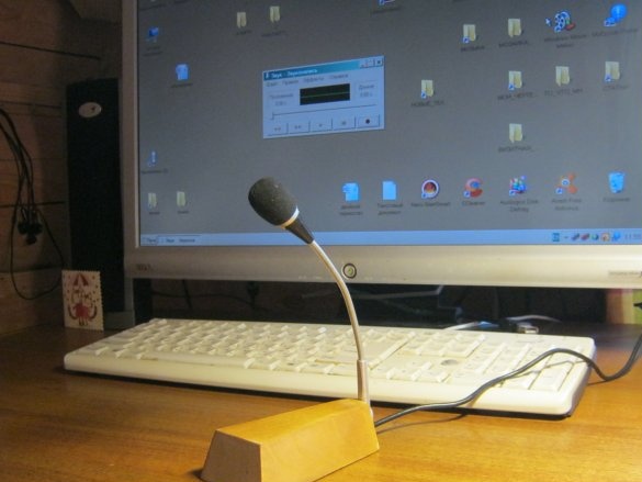
My computer is a working tool plus a bit of entertainment. Music, movies and photos. The usual range of tasks does not involve digitizing the voice at all. Our Internet uses a communication channel through a GSM network and has a relatively low speed and considerable delays between transmission and reception. Real-time voice and video communication in such conditions is difficult. In a word, they never used a computer microphone.
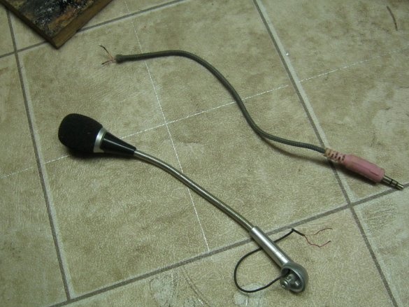
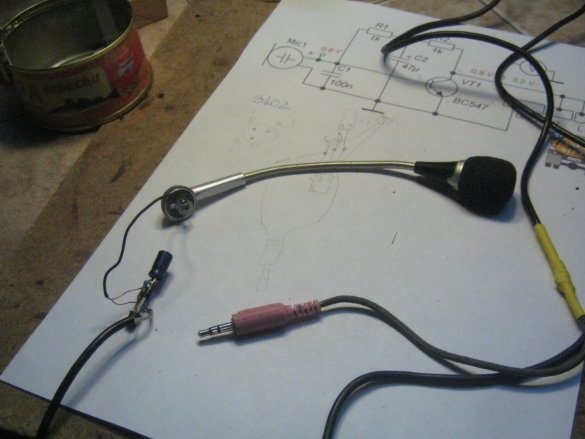
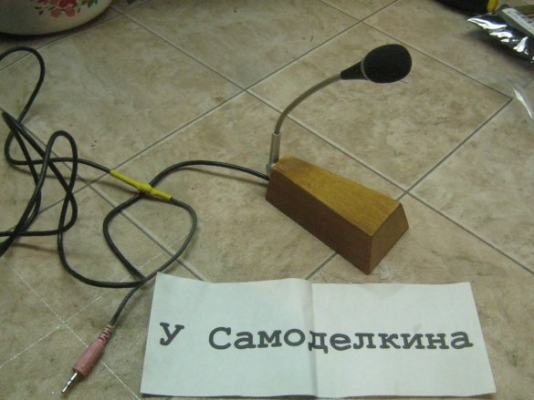
The child loves to make and edit unpretentious films with his dolls and has recently been puzzled - you need a microphone for the author’s words and generally thoughtful sounding of his creations. Had to get away. Having rummaged in boxes with electric trash, I found a whole ball of broken headphones of different sizes. They are now very common and there are inexpensive options - users, especially adolescents (the majority of wearable consumers electronic things) rarely differ in accuracy and patience. Headphones from such an audience are an expense item, and repairing inexpensive devices of this type is rather dreary. In a word, they flock and accumulate in a box. Among the small plugs stuck almost directly into the brain, there were several larger options, including with a microphone like an air traffic controller. For the same computer. I picked up a microphone more sympathetic, on a flexible metal antenna and with a foam cap from spitting and blowing, unscrewed it. The signal connector (pink) with a short tail also took from the same headphones. These are the original parts.
What else was needed for work
A set of tools for electrical installation, equipment for woodworking and painting. A piece of wood, paintwork, little things.
I checked the connector with a multimeter, connected the wires to a live thread and checked the microphone with a test inclusion. Nothing alive can be applied.
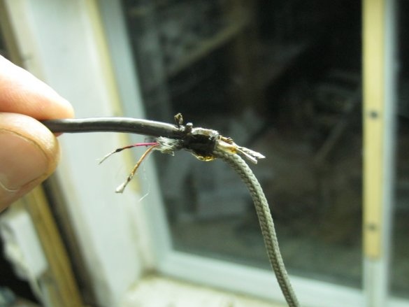
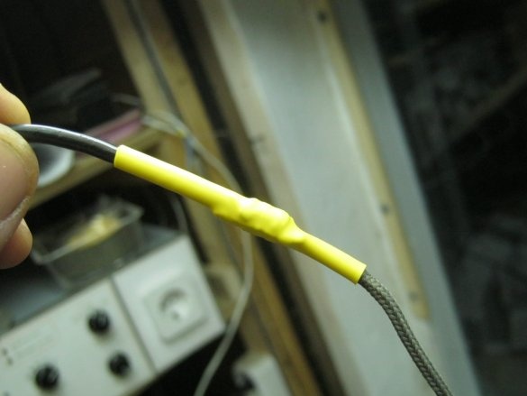
I picked up an old shielded signal cord as an extension wire. Pretty soft. I carefully connected it with the tail coming out of the connector - I fastened the two ends of the cords to the outer insulation with a bandage of threads with glue. He tinned the ends of the wires, soldered, insulated. The junction was insulated with a thermotube. I checked the finished cable with a multimeter.
I connected a microphone to the free end of the cable (again on a live thread) and tried to carefully evaluate its performance.Practice has shown that the sensitivity of the microphone is not too great - it works well, only being at the very lips as in the original design, here, a desktop option was seen.
The directional pattern of the microphone is almost circular - its sensitivity is approximately the same both in front and side.
Everything suggests that slightly increasing the sensitivity of the microphone, we can hope for convenient work with it in the desktop version.
Microphone amplifier
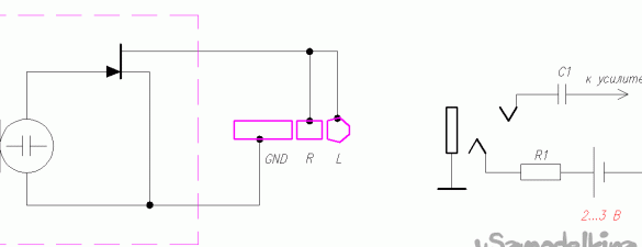
The type of microphone used is electret. In essence, it is a device structurally similar to a capacitor. To match the high impedance of the microphone with the relatively low input impedance of the amplifier, a matching stage is used, made on a field-effect transistor, which is located in the body of the microphone capsule. In general, turning on the microphone to the computer’s sound card looks like this.
A feature of the circuit is - direct current for the operation of the transistor and an alternating signal, flow through the same wire.
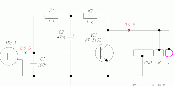
This power source can also be used to operate an additional amplifier stage. It is reasonable to place the cascade, perhaps closer to the microphone - this will reduce the noise level. The electrical circuit diagram of a single-stage electret microphone amplifier for connecting to a computer looks like this.
The signal from the capsule is allocated on the resistor R1 and fed to the base of the transistor VT1 for amplification. The transistor is turned on according to the scheme with a common emitter with a load on the resistors R2 and the resistor in the sound card. Negative DC feedback through R1, R2 provides relative constant current through the transistor. Compared to a microphone without an amplifier, the signal increased by about 10 times (22dB). The circuit needs shielding.
The KT3102 transistor is desirable in a metal case, but it will work in TO-92. It is permissible to replace with BC547, S9014, you can try KT315, KT312, etc.
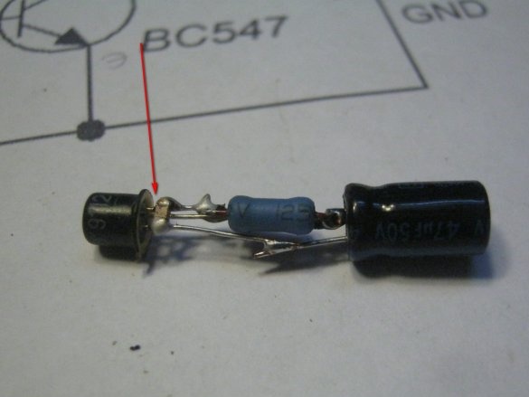
My amplifier was designed for a narrow and long compartment in the microphone stand. It turned out to be convenient to counter-mount the largest elements - a transistor and an oxide capacitor. The resistors were found not particularly small - MLT-0.25, capacitor C1 in SMD design. Case size 0805 is conveniently soldered directly to the wire terminals of the transistor (shown by an arrow). The only moment - you can not press on the middle of the assembly - you get a long lever and one of the contact pads comes off the SMD capacitor.
The amplifier stage is turned on immediately after the microphone on the foot. By trial inclusion, I was convinced of the operability of the circuit and its advantage over the simple inclusion of an electret microphone.
Sole
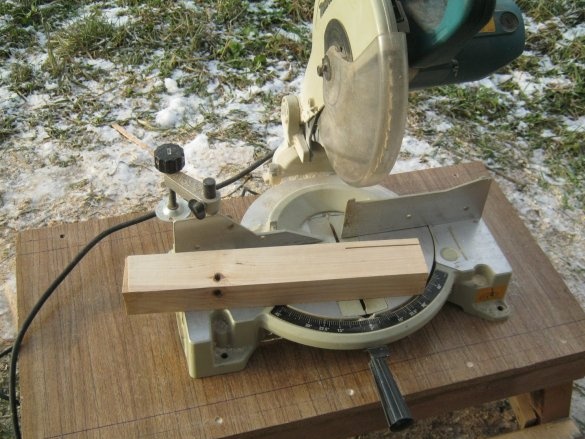
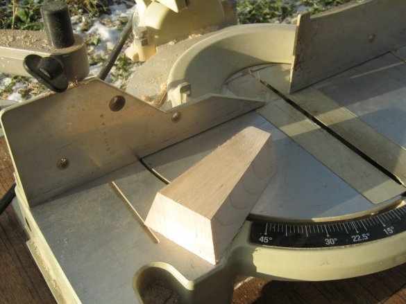
The sole of the microphone is made of a piece of a thick birch board turned up under the arm with the help of a miter (pendulum) saw. After several iterations, we managed to find nice bevel angles for such a base thickness. Work should be very careful - the workpiece is small and it is difficult to fix it with regular means. At each cut, the piece of wood must be firmly supported against the vertical emphasis, otherwise it can be pulled out of the hands with unpredictable consequences.
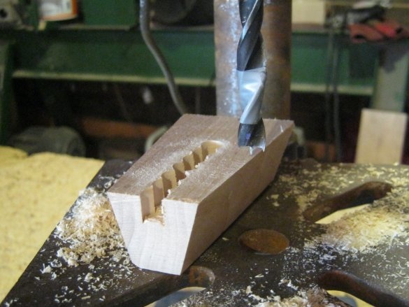
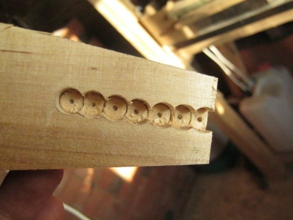
Groove - compartment for laying and fixing the cable and amplifier is made in the thickness of the wooden sole. I drilled a series of blind holes for this with some overlap. Drilled on the machine with a twist drill on wood ø10 mm. 3000 rpm In solid wood it turns out quite neatly.
I finished the outsole with two sanding paper numbers and finished it. Actually, at the same time I was engaged in the decoration of other pieces of wood, it turned out for the company. Among other things, I tried a new stain and varnish on the sole. He painted and varnished from a small pneumatic spray gun - a simple airbrush, with homemade compressor.
Assembly
I screwed the microphone leg to the rear vertical wall of the sole, above the outlet of the compartment. A long thin self-tapping screw, having flopped previously hot glue.
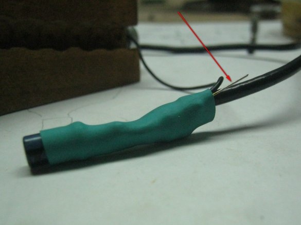
Shortened the microphone output, cut the end, tinned the ends of the wires. He formed both cables in one direction and soldered them to the terminals of the amplifier. A piece of tinned wire was soldered to the general output of the amplifier (arrow in the photo). Checked by test inclusion, isolated the amplifier with a thermotube.
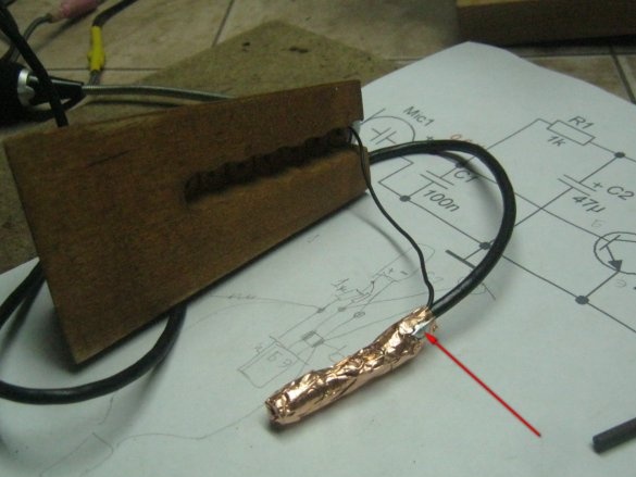
I wrapped the amplifier with a thin copper tape with a sticky layer, we use this for stained glass, although it is for shielding. He bent to the screen the output of the common wire, soldered. I checked the work with a test inclusion.
Flopped some hot glue to the bottom of the amplifier compartment and gently pressed the amplifier into it. I checked the performance, laid the wires and completely filled the compartment with hot-melt adhesive. After solidification, with a sharp knife cut off the protrusions. It was supposed to be three rubber foot-spots, but well worth it.
conclusions
The microphone works well, the daughter is very satisfied.
Of the negative aspects, it is worth noting the experimental finish - it turned out that the most beautiful Finnish varnish Yalo, giving a coating on very bare wood very similar to waxing, does not work well with stains. Alcohol and water based. He even dissolves the dried paint and draws it into the pores of the end sections of the wood. Up to complete discoloration. And even the preliminary primer does not help.
Babay Mazay, December, 2019


