Greetings to all readers of the site. I take this opportunity to wish everyone a Happy New Year! "We Wish You A Metal Xmas And A Headbanging New Year." Today you can read the instructions for manufacturing a mini plotter. It is made from old DVD or CD computer drives. This is not my first plotter of this kind, so when I write the instructions, I will refer to my other instruction, so as not to write the same thing twice. The first plotter worked well, I used it for different purposes. Just draw something, and also for the manufacture of printed circuit boards. Using a permanent marker, you can put tracks on the board, and then etch as usual. But the first model had small design flaws. I do not mean a small area of drawing or engraving, but the need to mount a part, board or sheet of paper on a small table. It is easier to make a moving table than the design that I propose, but it will be possible to work with large details. The size of the working area will be the same, as it is limited by the size of the DVD drive mechanisms.
Let's start collecting the necessary:
- CD-ROM, DVD-ROM or similar mechanisms 4 pcs.
- Arduino Uno
- Arduino CNC Shield v3
- Drivers for a4988 stepper motors and radiators for them 3 pcs.
- Servo SG90
- Platform universal Tamiya 70098
- Enclosure from DVD-ROM
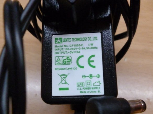
- Power supply for 5V, 3A
- Homutiki
- connecting wires
- Connector 2.54 mm Dupont
- Bulgarian, electric jigsaw, drill
- Soldering iron, solder, rosin
- Thin elastic
- Drills for metal or wood 2, 3, 4, 5 mm
- Screw 3x20 mm or 4 mm x20 mm
- Marker, best thin
- Nuts, grovers and washers 4 mm
- Hot glue
- Wood screws 2.5 x 25 mm, 2.5 x 10 mm
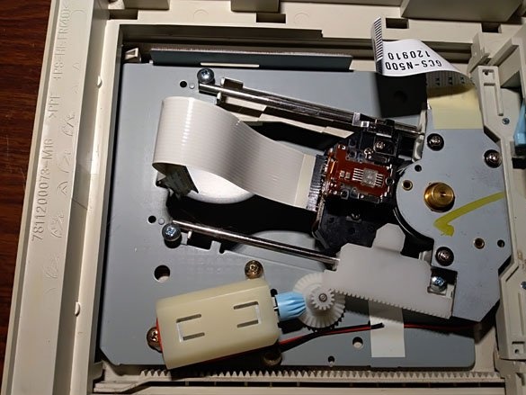
Step 1 Disassemble the disk reader.
First of all, we need to find and disassemble 4 DVD drives. Most likely, a CD-ROM will do. The main thing is not to stumble upon such:
There are no stepper motors in it, and therefore we cannot use its mechanism. From these, it will be possible to take only the body, axles, carriage.
We disassemble suitable DVD drives. After parsing, we put all the boards into a box, then we will hand them over. Plastic parts immediately for discharge, i.e. for recycling:
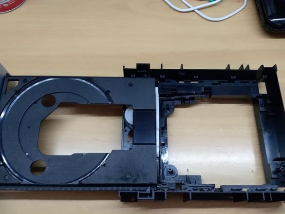
We get the internal mechanism, and it should look something like this:
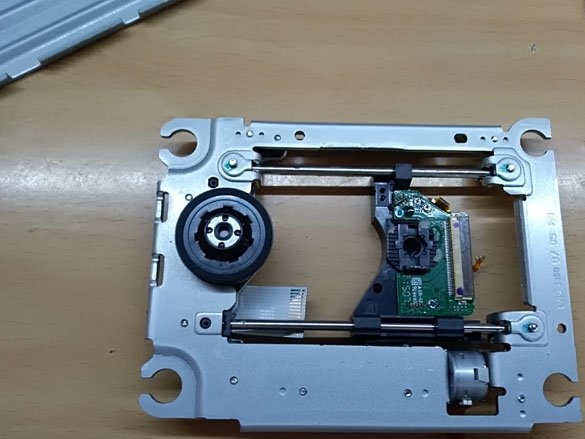
We turn off the big round motor, we do not need it:
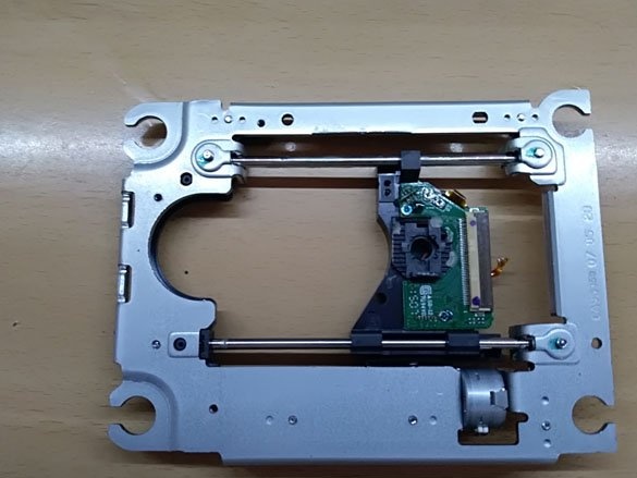
And put the mechanisms aside for now.
And we still have metal parts:
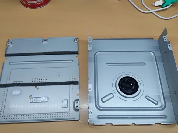
We take one of the large covers for further processing, the rest we hand in for scrap. Recycling rules!
Step 2 Making the case.
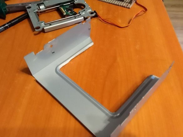
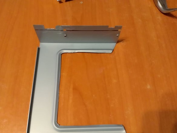
The difference between the first and second versions of plotters is in the construction of the Y axis. For the base, take the top cover from the DVD-ROM. First, shorten it. We take two identical internal mechanisms, they will be responsible for the movement of the Y axis. We measure their length, they are different, they can differ by several millimeters. But usually it is 125 mm. We cut our cover from the front so that, starting from the back bend to the front, 125 mm remains. And cut off the protruding corners intended for fastening the cover. In the middle of the base, a 110 x 90 mm rectangle must be cut:
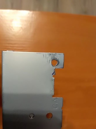
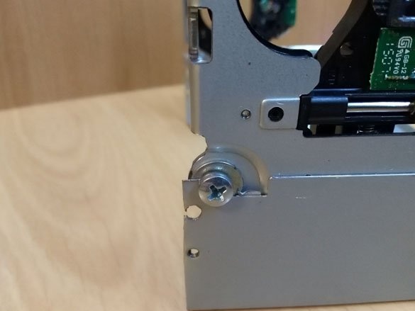
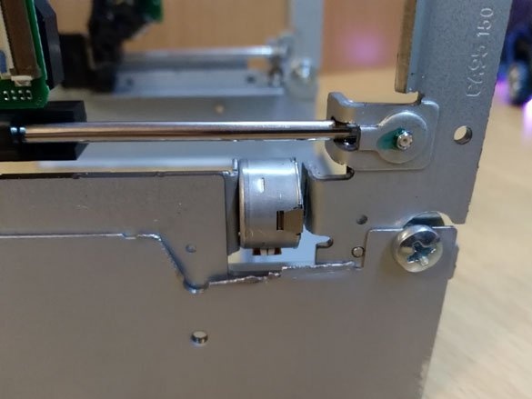
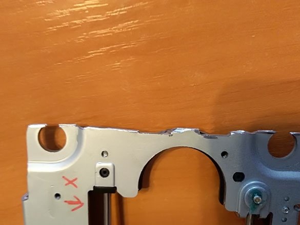
Now we apply the pending identical mechanisms to the side walls, from the inside of the cover. The cutout for the large round motor should be in front, and the lenses on the carriages should be directed outward. Thus, you will have one step motor of the mechanism below, and the second above. We make it so that from the bottom of the cover to the top of the mechanisms it is 120 mm, and mark the places of attachment to the covers. In the marked places we extend the holes 4 mm, you should get two points of attachment to the mechanism. One in front:
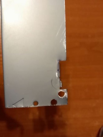
And one behind:
Once again we apply the mechanisms, mark on the basis of the place where the engine or other parts interfere with the fit of the entire mechanism to the base, and cut them off. After that, we fix the mechanisms on the base with the help of 4 x 12 mm bolts with 4 mm nuts:
To ensure that all mechanisms are level, it is convenient to mount them by placing the base sideways. Do not forget to check the distance from the bottom of the base to the top of the mechanisms:
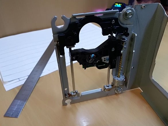
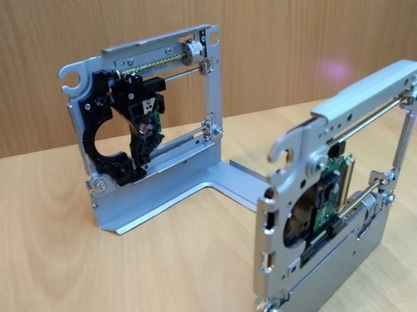
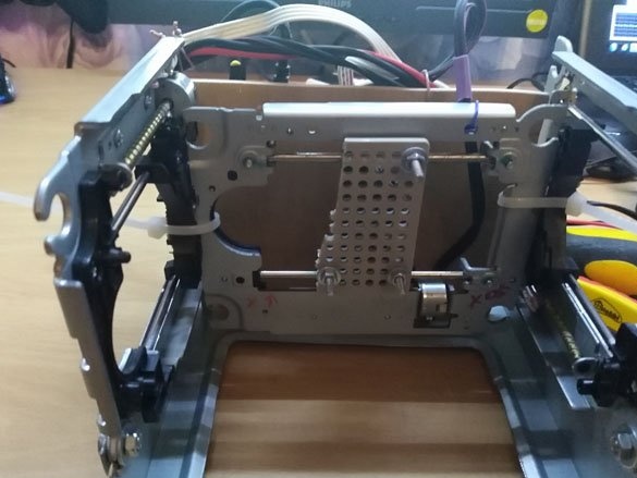
Attaching both mechanisms, we get the assembled Y axis:
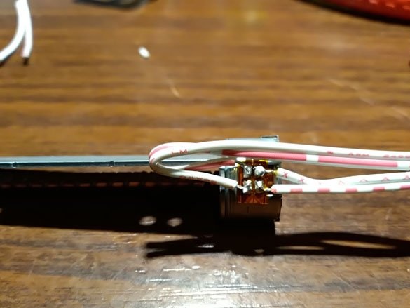
Now it will be convenient to distract from the metal and take a soldering iron. It is necessary to remove the stepper motors from the mechanisms and solder wires to them, all four, about 15 cm long:
More interesting, I promise! We take the third mechanism, this is the future X axis. We are trying to place it between the Y axis carriages. Most likely it will not fit a bit in width. We measure the size we need, that is, the distance between the Y-axis carriages. Most likely it will be 120 mm. And cut off the mechanism of the X axis for the size we need from the side of the engine we shot. For this, I think, it is most convenient to take a grinder, since the metal on the mechanism is thick and can not be taken with simple scissors for metal:
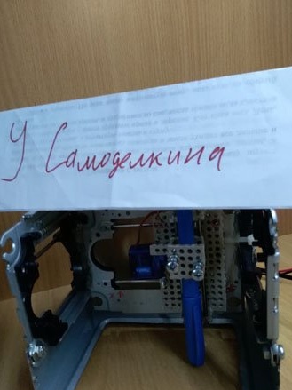
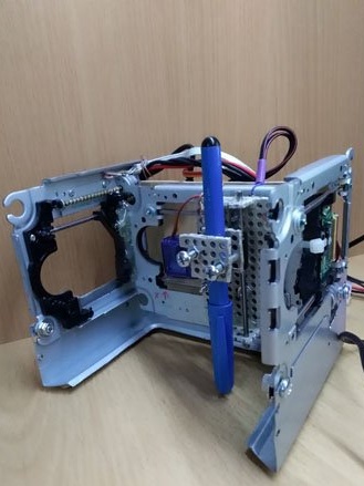
On the carriage of the mechanism we have prepared, glue a piece of the circuit board or universal platform Tamiya 70098. This is necessary for attaching the working tool. Place the X axis in its place. Using clamps, we fix the axis in its place, but not so far so far:
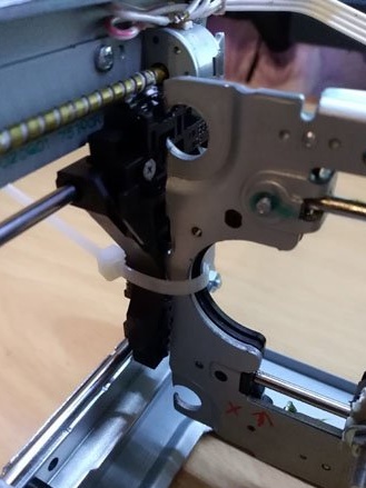
It should look something like this:
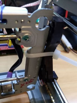
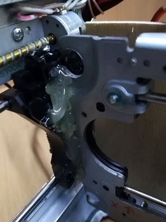
Now take the ruler. We place our plotter on a flat table, with at least one side wall. So that the plotter abuts against the wall and stands flat on the table. Moving the X axis slightly makes it 110 mm from both ends of the table, that is, it is horizontal to the surface on which it stands. And we make an even distance from the side wall to the edges of the X axis so that the axis is exactly aligned with the Y axis. Having achieved the dimensions we need, we tighten the clamps. We take a hot glue gun and glue the X axis in this position to the Y axis carriages. After waiting for the glue to cool, the clamps can be cut off, they are superfluous:
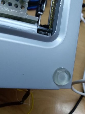
At the bottom of the base, silicone or rubber feet should be glued so that the plotter glides on:
Step 3 Work Tool.
For the plotter, we will use a homemade working tool. We will draw with a marker, preferably as thin as possible. It will be possible to draw with a pen. The manufacture of such a holder and mechanism is fully described in detail in “Step 2. Production of the holder of a writing object.” my instructionsDVD mini plotter»
Plotter - this is not the limit on this basis. You can install the laser module using the instructions "Laser engraver from DVD version 2.0»
The basics are fully compatible.
Step 4 Electrician.
For starters, cut a rectangle 130 x 110 mm from chipboard 3-6 mm thick. This will be the basis for electricians.You can use plastic or textolite, if you take metal, make sure there is no short circuit. Mount Arduino Uno on our rectangle:
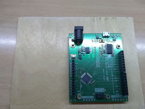
On top of Arduino we put CNC Shield v 3. Now we need to install microstep 1 \ 16 on the engine drivers. We will install A4988 drivers, therefore we will adjust the settings for them, if you have other settings, respectively, will be different. For the Y axis, we use two stepper motors, so we put two jumpers opposite the designation of the Y axis, so we will duplicate the signal of the Y axis on the A axis. Where exactly these jumpers are indicated in the picture below. We also need to install jumpers on the MS, MS1, and MS2 axes X, Y, and A. The jumpers MS0, MS1, and MS2 are located between the driver installation pads:
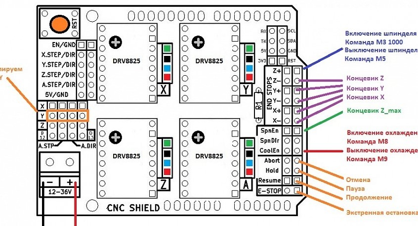
The CNC Sheld has an operating voltage range of 12 - 36 V, but we have stepper motors running from 5 V, so we will also use CNC Sheld from a 5 volt power supply. The power supply must be taken quite powerful, at least 3 A. The power supply is approximately the following:
The working tool, in our case, is the servo SG90, we connect as follows. A positive wire, red, we connect to +5 coming from the power supply, you can not power the servo from the +5 contacts located on the CNC Sheld (they come from the current regulator on the Arduino UNO, and are not designed for high load), GND (black wire) from SG90 connect to the GND CNC Sheld, and the signal wire (yellow) connect to pin + Z on the CNC Sheld.
Now you need to set the operating current for the stepper motors. This process is described in detail in the “Laser engraver from DVD version 2.0»
We read the fourth step of the instruction “Step 4 Setting the motor current limit.” and do everything according to that instruction. But since we have a plotter, and the marker will create resistance to the movement of the axes, we will increase the current a little so that there are no missing steps:
Vref = Imax * 8 * (RS)
Imax - current of the stepper motor
RS is the resistance of the resistor.
In the case of a plotter:
RS = 0.100.
Imax = 0.55
Vref = 0.55 * 8 * 0.100 = 0.44 V.
As a result, between the variable resistor of the stepper motor driver and GND there should be a voltage of 0.44 V.
Step 5 Software.
First of all, you need to download the Arduino IDE, it's best to do it with official site
We will use the GRBL firmware. To operate the plotter with a servo drive, it was specially changed. Download it
Unpack the downloaded archive along the installation path of the Arduino IDE, in the “libraries” folder. We turn on the programming environment and go along the path “file” - “examples” - “grbl-servo-master”. Download the sketch to Arduino. The plotter is controlled via the serial port.
To start, it remains to download the program for transcoding pictures into gcode, understandable to the plotter. The most comfortable, in my opinion, LASERGRBL. Download it
Then everything is simple, start LASERGRBL, connect the plotter, connect to it in the program and try to send $$, we should get the parameters in response.
The plotter works well and with a sufficiently large resolution, but the thickness of the marker is quite large. Therefore, small labels may not work.
But ordinary drawings come out well