» Electronics » Metal detectors »Scheme of a more advanced detector" Kid FM2 "with metal selectivity

The scheme of a more advanced detector "Kid FM2" with metal selectivity


The Kid FM2 circuit is a bit complicated compared to the simpler "Kid FM”, Added new parts, added light indication of metals, the sound in the speaker is amplified (headphones are not needed), and the device itself has become more stable in operation. But all these improvements will not hinder to assemble it to people far from electronics.

The device is powered by a simple crown 9c, the detection depth is basically no more than the diameter of the search coil. Perfect homemade metal detector for the beach or to the lookout.

For assembly we need:
1) Textolite
2) Drill
3) Varnished copper wire 0.3mm
4) Soldering iron

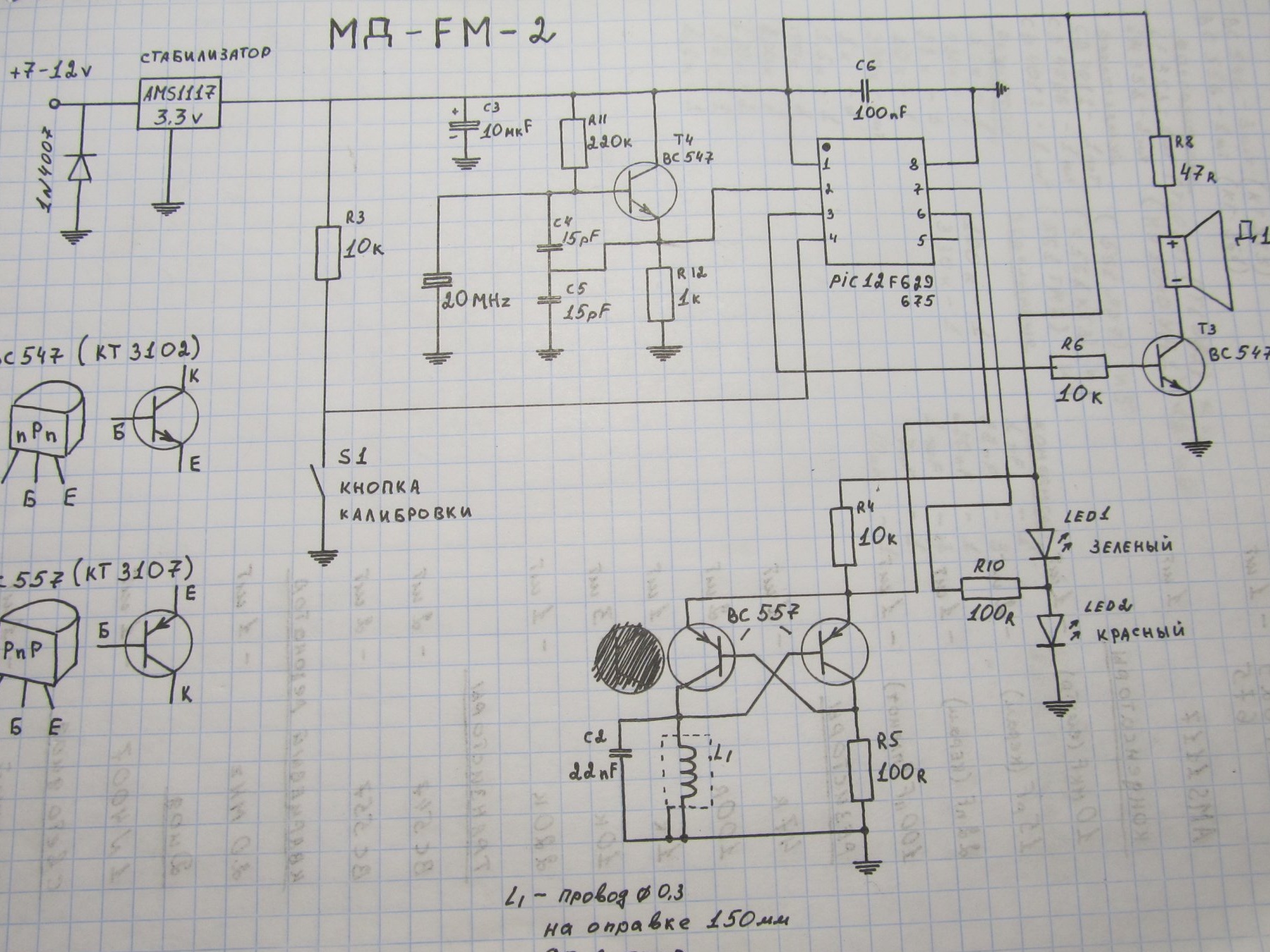
Here is a diagram of the improved Kid FM2

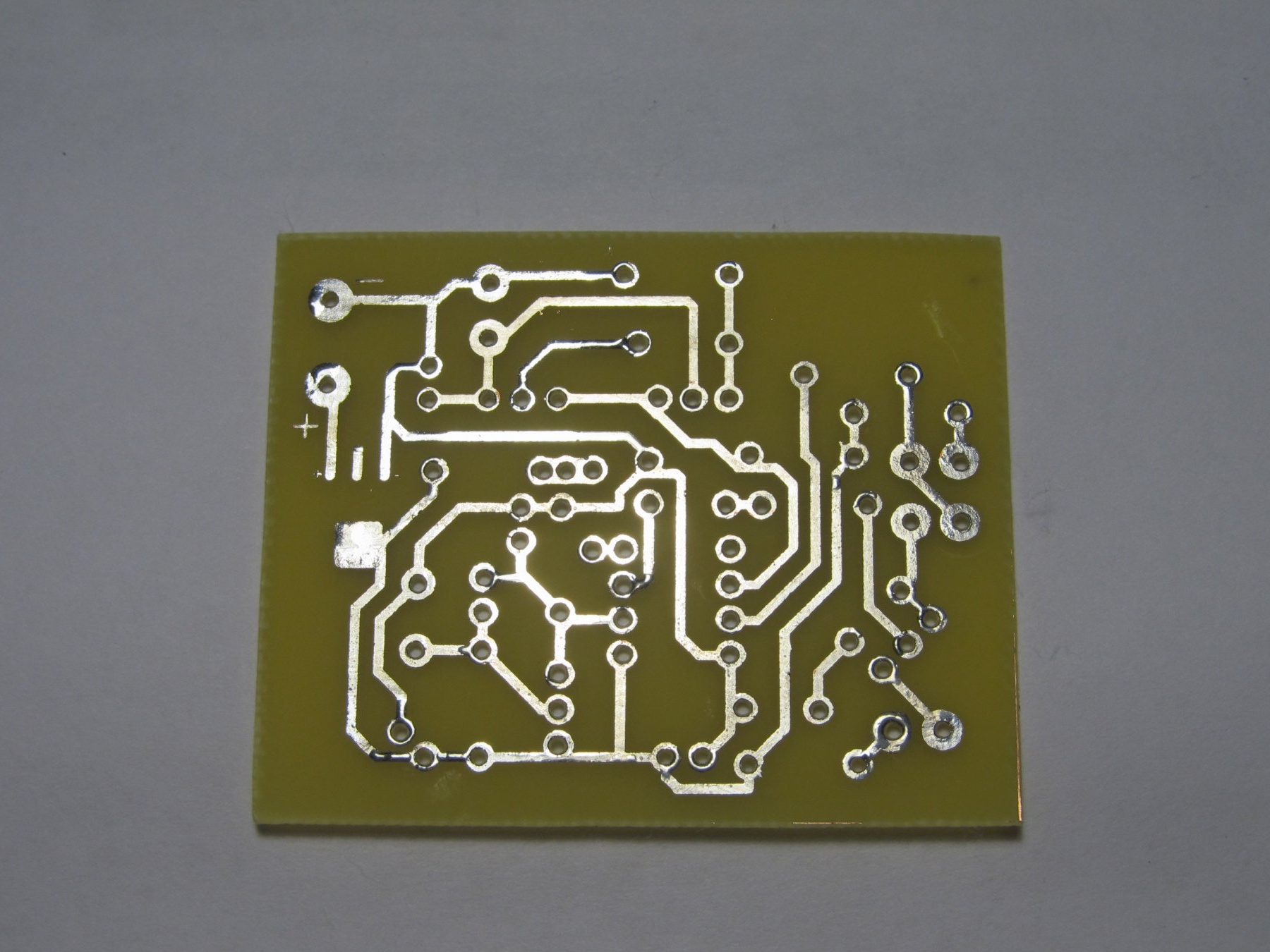
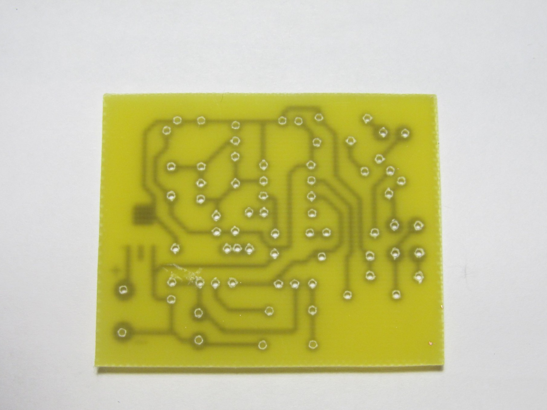
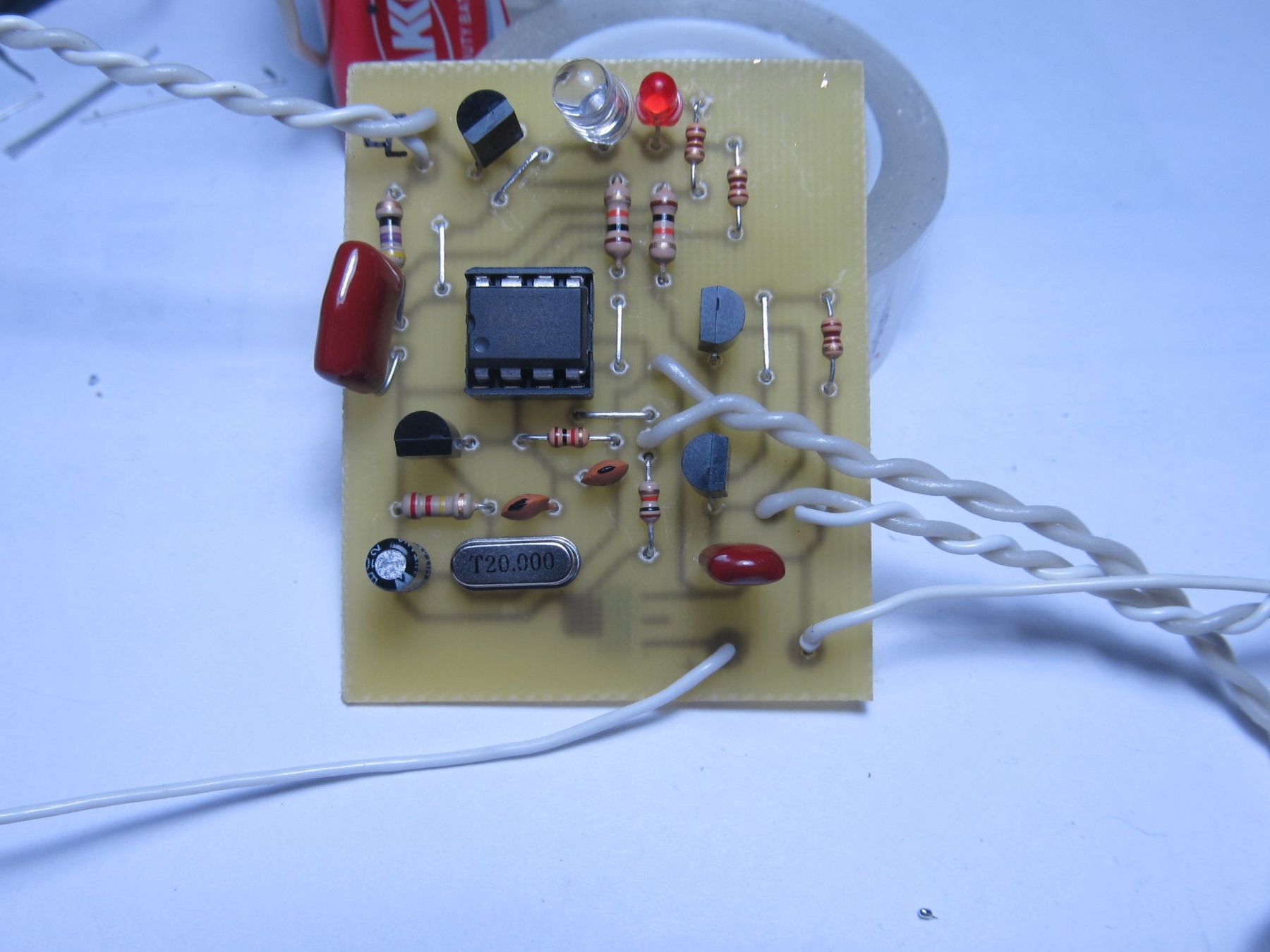
I specifically made the board for DIP components, it’s easier to mount


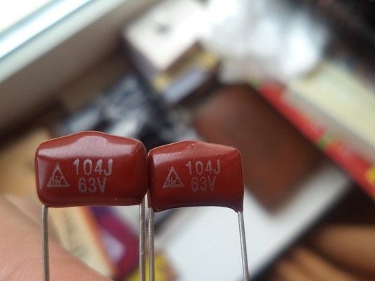
I must say right away that the capacitors C2-22nF and C6-100nF should be film
The scheme of a more advanced detector

We place all the details on our board according to the scheme

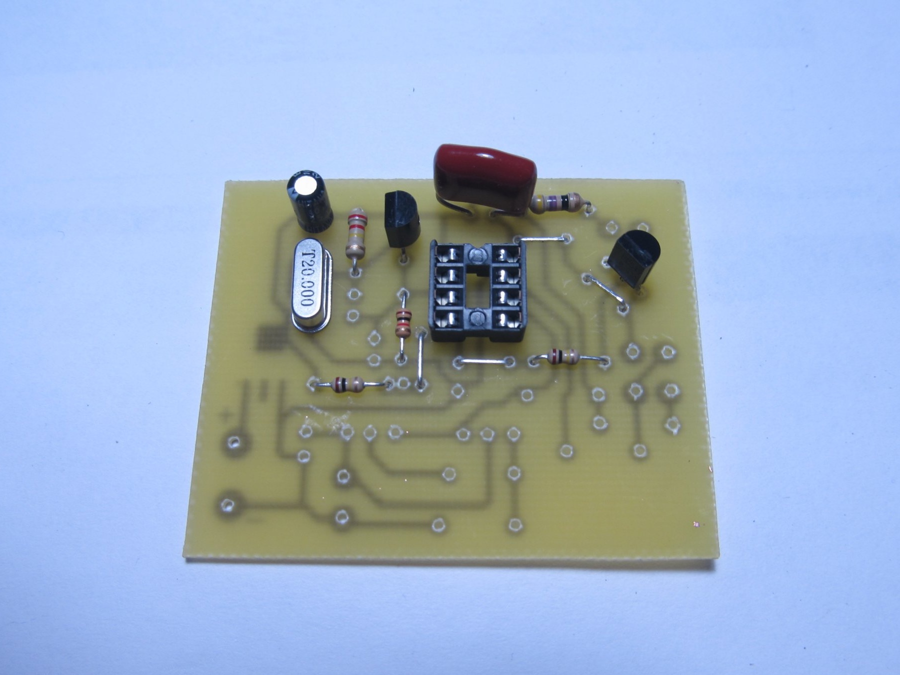
There are circuit boards on the Internet. But they are all in SMD, I did not find in DIP, so I did mine. I will post the file with the board below, but the details and jumpers are not signed on it, so it will take you to collect from the photo or make your own board or SMD.

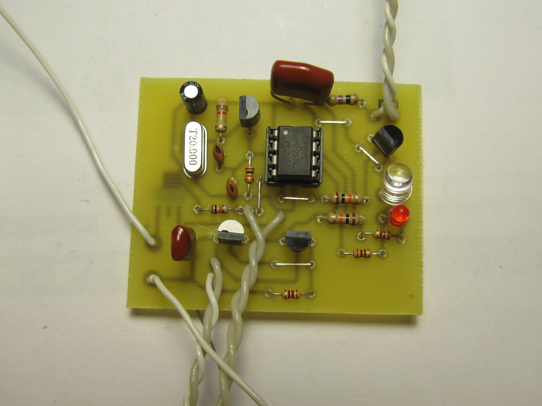
Well, everything is soldered into place


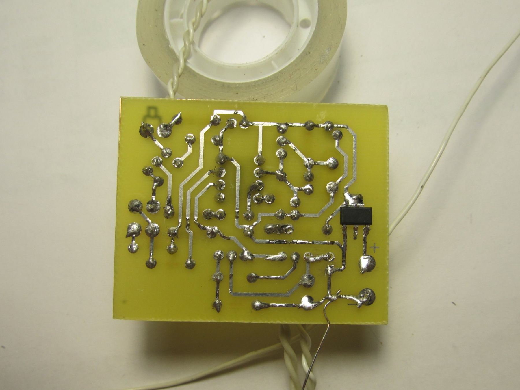
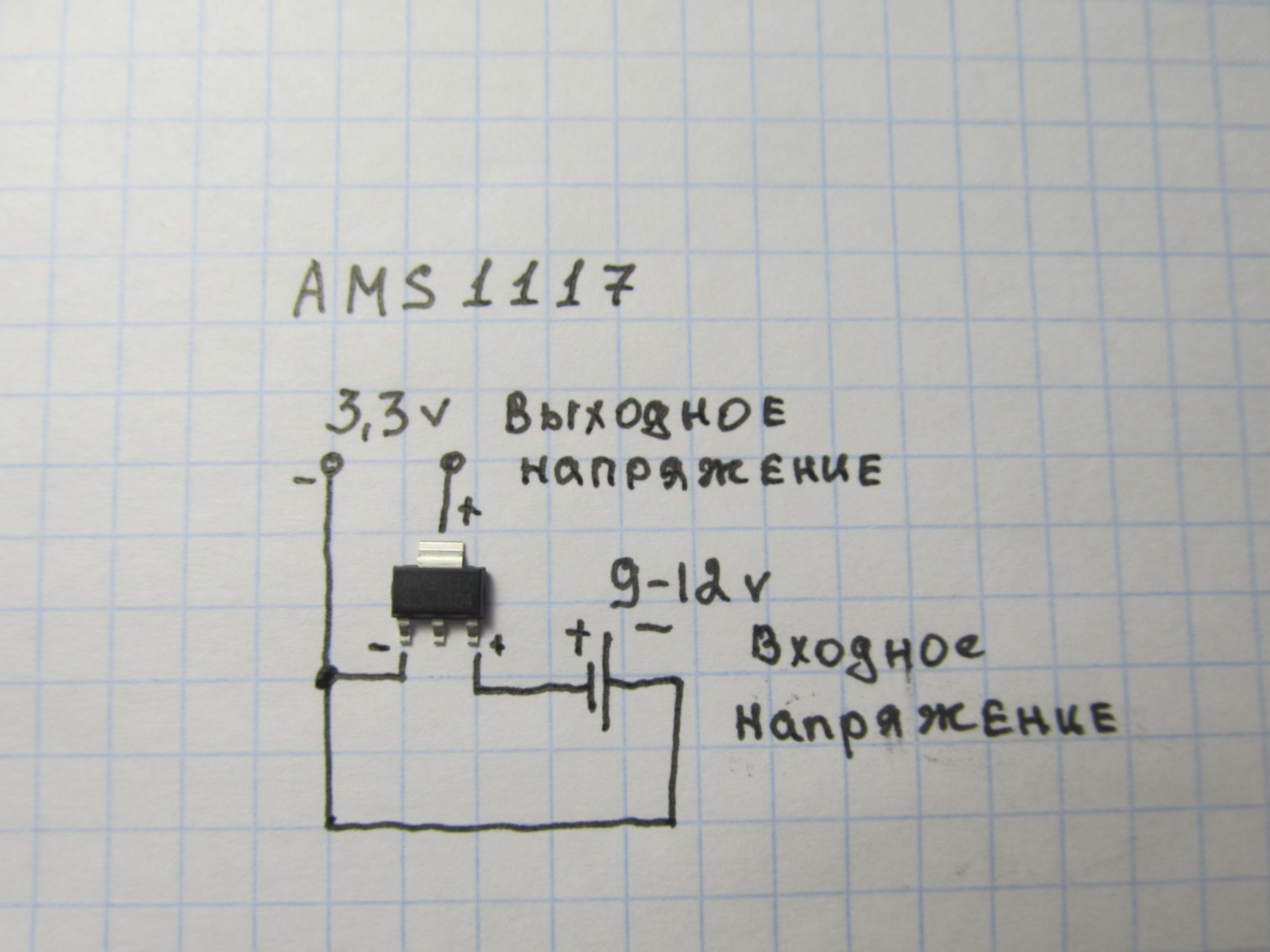
Voltage stabilizer AMS1117 -3.3v.

I advise you to take the LEDs in different colors, I took red for ferrous metal and blue for non-ferrous.

Proceed to winding the coil. The diagram says about a coil with a diameter of 15cm. But I decided to do less, because the smaller the coil, the finer the find she sees, if the coil is large, then the detection depth is slightly larger. But she sees little goals. Since the detection depth is not very large in this metal detector, I decided to make a 10-11 cm coil for myself. To do this, you need to wind a wire on a 10 cm mandrel (I don’t have 0.3, I wound 0.4) 130 turns.

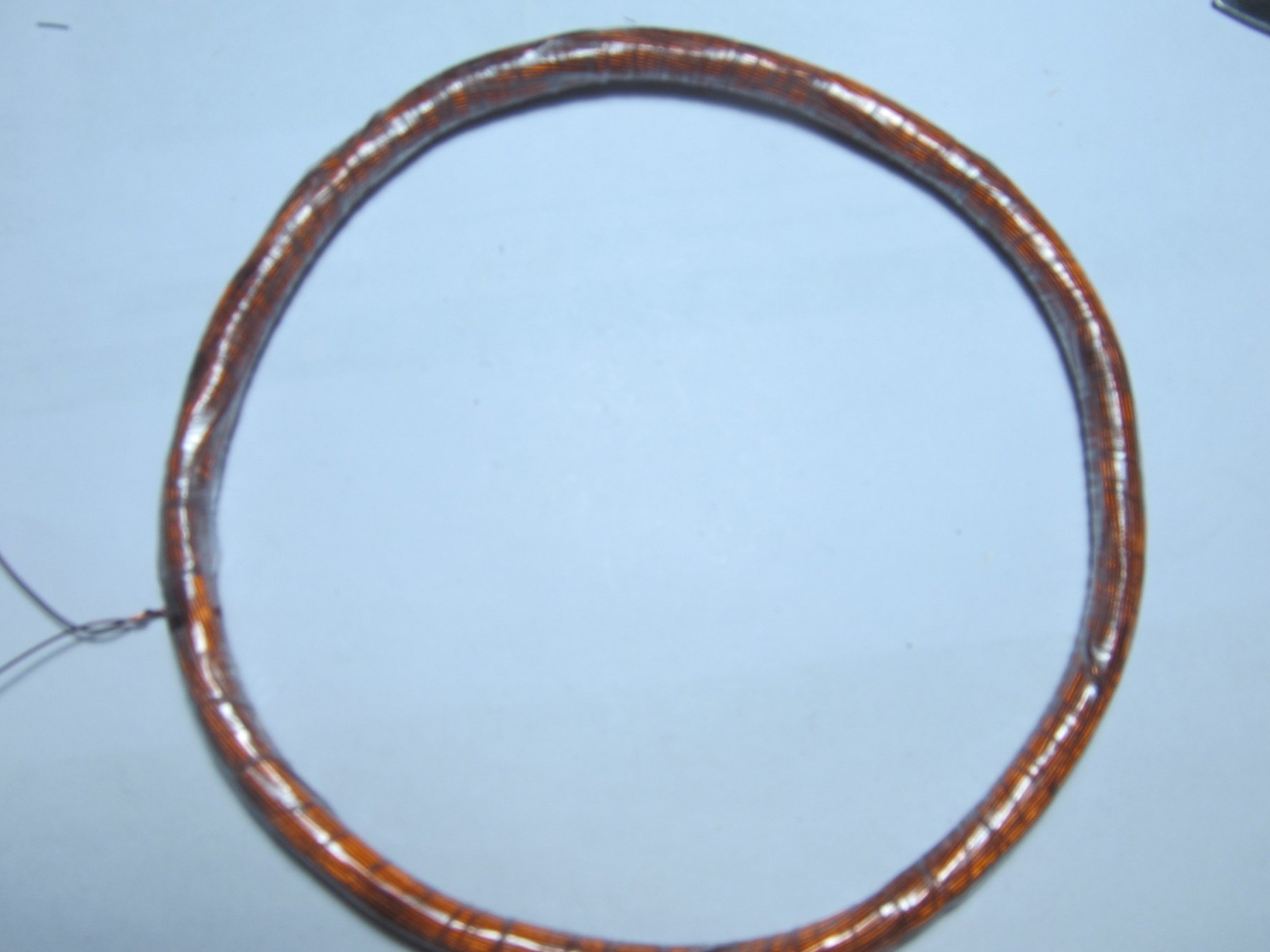
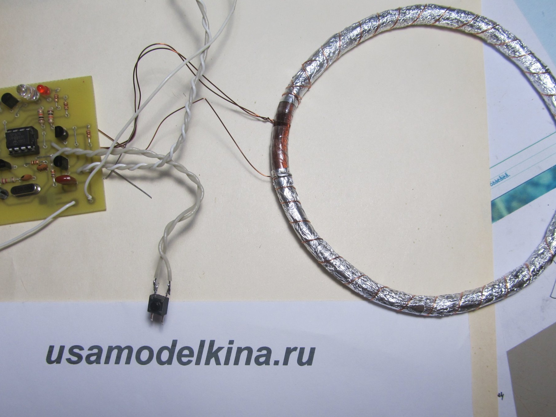
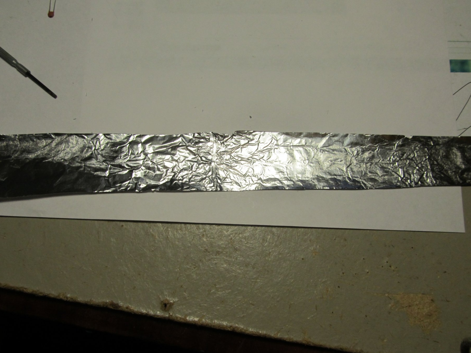
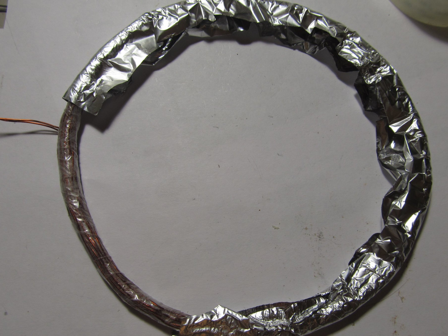
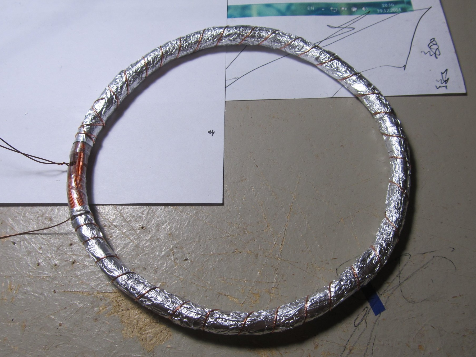
Coil as in first baby wrap with tape and screen.


Here is a photo of the entire device assembly

Next, you need to flash the microcontroller and you're done.

When you turn on the device should make a sound (peak-fute), if the Fute is, then the device turned on and started working.If at all, I didn’t pick it, then the error in the board or not working quartz.

If you pick it up, but there is no treasured Fute, then either the coil is not wound correctly or the wrong capacitor C2 is 22nF. It didn’t start for me for a very long time, everything was picking and picking, but there was no treasured Fute. It turned out that instead of a 22nF film capacitor, I put a simple ceramic one and did not tighten the coil tightly and did not shield it.

Basically, the device is not very difficult to assemble, the main thing is to flash the microcontroller, who does not have a programmer, please contact, I will help with the firmware or in comments.

Below I posted a video of the metal detector, as well as firmware and board files in DIP.

VIDEO WORKS


FIRMWARE MetFM2_675.rar [1.99 Kb] (downloads: 7943)

PAY Plata-DIP.rar [7.13 Kb] (downloads: 7986)
9.7
10
8.3

Add a comment

    • smilesmilesxaxaokdontknowyahoonea
      bossscratchfoolyesyes-yesaggressivesecret
      sorrydancedance2dance3pardonhelpdrinks
      stopfriendsgoodgoodgoodwhistleswoontongue
      smokeclappingcraydeclarederisivedon-t_mentiondownload
      heatirefullaugh1mdameetingmoskingnegative
      not_ipopcornpunishreadscarescaressearch
      tauntthank_youthisto_clueumnikacuteagree
      badbeeeblack_eyeblum3blushboastboredom
      censoredpleasantrysecret2threatenvictoryyusun_bespectacled
      shokrespektlolprevedwelcomekrutoyya_za
      ya_dobryihelperne_huliganne_othodifludbanclose
155 comments
The problem until it started: the stabilizer 3.3V is heated. What firmware was used, or works with any of the three?
with resistor R8, power supply + 7-12 volts according to the scheme, you have 3.3 volts.
No problem?
Author
Good afternoon !
To you mastec (wrote 2 June 2015 20:23)
On the developer's site, the scheme is a little different. Have you redid your scheme?

5 leg is not connected.

Here I spread
Thank you, I already opened it, downloaded another layout and everything opened)
I’ll ask, if it’s not difficult for anyone, drop it to alex_8888@tut.by plata dip in Word, otherwise I can’t open this file either (
Hey. I have a question. Can I make one to order? Send by mail
Hello, I ask you to discard the full name of the parts for the “Baby FM2” scheme, as well as an online store where you can purchase these parts since I live in the Republic of Kazakhstan, we have no choice in radio parts stores. Request for assistance with firmware chips. Thank you in advance for your help.
I have problems like Van (wrote June 26, 2015 22:28), but there is another red LED that is silent and there is a sound indication. I rolled 3 coils 1 as you have and two as in the diagram. What could be the problem? And why the red LED is silent. polarity is correct.
Group: Visitors
Hello, tell me please, I’ve wound everything up, collected everything, when I turn it on, a double test takes place, then the desired fute (everything is like in the video), but then there is a full booty, and it has three options, the first one is right after the fute is a red LED (you have it bright blue) constantly flashing and beeping, respectively, as if something had been found, the second - after the fute is silent normally, but just bring it up and remove the non-ferrous metal, and again, as in the first priest, it continues to constantly squeak and blink, and the third priest is the same and secondly only with black me tall, well, and accordingly blinks green peeps, the question is - where did he get the shob to him, he understood everything? ))))), which way should I look what to check? waiting for advice, thanks in advance
why does this metal detector react to hands?
olgiy
Good day! Buy a ready-made kid FM2, can I buy it?
sa4er
Hi guys. As a beginning amateur radio amateur, I want to ask, but can I replace the transistors with some sovetskie ones (in the orange case)? And will quartz from the motherboard fit 25.0 (and some letters) on it? Thanks.
starik
Hello.Guys, help me with the peak firmware on kid fm2. Made last year right down to the case and coil. The controller is not who can not flash. The circuit is assembled correctly, everything is checked by an oscilloscope. Programmers cannot. He addressed three guys. He gave them everything on a flash drive. No result. I myself do not understand programming. I'm already old for this. For the transfer of the finished controller I will pay how much you say. Help out the guys ... Thank you.
Electronik83
How can boards be developed like this? And why the jumper drain on one simple circuit on the board?
You write: "To do this, you need to wind a wire on a 10 cm mandrel (I do not have 0.3, I wound 0.4) 130 turns." and Coil32 program when you enter this data produces 140 turns? Explain to me how important this is? or do you have a typo in the text?
Hello Vadim! Please write if I program with this programmer Pic12f675 if it does not burn because it has 3.3 volts power, and the programmer has 5 volts. Thank you in advance for your reply!
12f629. Or erased sold.
Author
yes like that, everyone has it, you don’t have one. Exactly that Peak use, what is the full name ???
Author
Perhaps look here http://signalsam.blogspot.com/2015/05/blog-post_68.html, there is a program
Leafing through, no.
Author
when the peak is read, the slider is down, it is there in the lower right corner
Tell me, if you use a ferrite rod with a winding instead of a coil? Is it possible and how to make a coil calculation in this case &
I bought a new peak, read it, at the end there is no constant.

The original does not match the stitched peak.
What peak voltage do these peaks have?
Author
constant should be anyway
If quartz is remote, the constant is not written.
Author
Yes, 675 and 629 she is. It depends on what firmware you are comparing ??
I'm flashing it on the ChipStar programmer. For some reason, the checksum does not converge with the source, and when I compare the firmware with the original, that is, the differences.

Is there a constant like 675 and 629?
Author
in each peak they are different, this is the microcontroller indicator number or something like that. Before flashing the peak, you need to read the microcontroller there, these 4 digits will be below, after you sew the program, these numbers need to be entered in the same place, for example, the PicKit programmer does this automatically. There is a video where you can see the constant with the firmware (http://signalsam.blogspot.com/2015/05/pickit2-lite.html)
Can a screenshot be taken, what are the 4 digits?
Author
when flashing the controller about the constant did not forget ??? 4 digits at the very bottom ??
Try without a coil speaker will pick?
There is nothing in the dynamics. Equally, with a coil connected, without a coil. It turns out that the generator does not start. The controllers sewed on the industrial programmer, after the firmware the program asked to write some kind of configuration. Maybe it did not sew correctly?
Author
Is there sound? and which ??? or blinks stupidly, reacts to the reset button ??? It looks like a problem with the coil too
Author
at the expense of POPA, the problem is in the reel, maybe the screen is not wound correctly or connected incorrectly, if everything is correct, then play with the turns of the coil (add or turn off the turns, try, I played myself) on the video I also showed that after It also works itself, but after a reset it already starts to work normally (also the coil is a little not maintained).
Hello, tell me please, I’ve wound everything up, assembled everything, when I turn it on, a double test takes place, then the desired fute (everything is like in the video), but then there is a full booty, and it has three options, the first one is right after the fute is a red LED (you have it bright blue) constantly flashing and beeping, respectively, as if something had been found, the second - after the fute is silent normally, but just bring it up and remove the non-ferrous metal, and again, as in the first priest, it continues to constantly squeak and blink, and the third priest is the same and secondly only with black m etall, well, and accordingly blinks peeps green, the question is - where did he get everything to him to take the Schaub? ))))), which way should I look what to check? waiting for advice, thanks in advance
I requested 629 two pieces with this firmware, the second LED blinks and that's it.
Author
yes fits
Is this firmware on 629 suitable? FIRMWARE MetFM2_675.rar
Author
See the power, maybe somewhere on the board cant, the coil screen correctly connected ?? maybe they messed up the firmware they are different for the 1st and 2nd
Hello, please tell me what the problem is. Kid 2 started up normally at first, but how to bring metal to the reel he will pickup 2-3 times and reset, but then I turned it off for a couple of minutes and turn it on and it stupidly beeps like a stopwatch. The first kid worked more or less often had to be reset, today he stupidly stopped seeing the blackbut but it works stably, I don’t understand for heh.
Author
K73-16-630V-0.022 mkf-5% I don’t know what kind of capacitor it is, but the conder in the coil needs just a film or metal film (required)
On the stabilizer, with AMS 1117, this was not, he just does not heat up with me. you can put any main thing that would have an output of 3 to 5.5v.
I welcome everyone. He assembled the circuit, works, shook three different coils of 10, 13, 15 cm with a different wire 0.3 - 0.4, start up with everyone.
A question for connoisseurs, Conder in parallel coils affect sensitivity? just got such a K73-16-630V-0.022 uf-5% Will it work or do you need to choose the minimum voltage and select the capacitance?
Why did I ask about sensitivity ... it reacts normally to large objects, but let's say a golden ring (even with a 10 cm coil) takes somewhere from a height of 1 cm and at the very contour of the coil.

Another moment, having remade the board a bit, I put such a stabilizer IRU1206-33CY, as far as I understood the TTXs are the same, only another pin. It is not sickly heated enough and the operation of the device depends on its cooling. If left without cooling, the device starts to fail and restarts, I'll try to install the radiator. With AMS 1117, who was this?
Author
in the photo of the circuit there is data on how many turns and which wire to wind the coil, look carefully + in the description I gave the dimensions of another coil. the resistors are all rated as in the diagram (you see something is mixed up), only one is added at 100 ohms per LED.
read the diagram and description correctly. About the diode, I also already answered that I just did not put it. Do not be lazy, sometimes it is useful to read comments. The scheme is fully working, I collected a few, they all worked, people also worked if the scheme was followed.

in the photo it seems that resistors of a different rating due to lighting, and since everything is exactly according to the scheme, you always need to do everything according to the scheme, and not according to the photo
There is a program for calculating the coil. Winded 0.4 wire. 10 cm. Diameter 130 turns. 0.35 wire, diameter 150mm. 103 turns.
-_-
Hello, the question is, but is the ORIGINAL EXACTLY SUCH a scheme? AND WORKING? for some reason there are a lot of discrepancies with your collected from her, I wanted to collect, but I was disappointed, I don’t have a coil rating, they all wind up randomly, I would like the exact size of your mandrel and the exact number of turns, you might have grown together because the resistor ratings are mostly different ? instead of 100 Ohms you have all of them 110 Ohms, instead of three 10 kOhms you have four 10 kOhms on the board, there is no diode, I have not penetrated all the tracks of your soldering, and it’s a pity the values ​​of all capacitors are invisible, please, sooooo much if made your post separately, posted a video of how everything works for you, they gave the idea to people and all instructions such as how, delve into your board, sort it out again, and please help your readers, unless of course you originally intended to hang people’s ears ( do not be offended if that). Sincerely .
Author
Well, that’s all right, the article’s date is fresh, there’s still no week, the scheme is modernized and the firmware has been changed
About the roll yes, it’s easier. http://smartelectronix.biz/publ/prostoj_selektivnyj_metalloiskatel_malyshfm2_ra
bota_nad_oshibkami / 1-1-0-74
Author
This scheme was taken from the developer's site, it seems to be from Lugansk itself. I just redid the board in DIP, added 1 resistor to the LED in the diagram not shown, and set another voltage regulator, which does not require additional resistors. Show me the diagram from the developer's site where 5 foot should be connected?

We advise you to read:

Hand it for the smartphone ...