» Electronics » Power supplies »Charger for 18650 from trash

Charger for 18650 from trash


Assembled into one design several simple circuits and blocks.
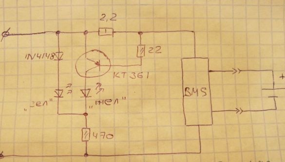
The scheme is very simple and soldering it will not be difficult even for a novice soldering iron

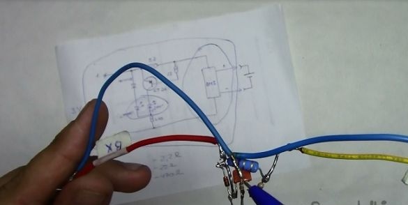
Three resistors, transistor, diode, two-color LED. We solder by hinged installation.
Details can be obtained almost everywhere. BMS from any battery, the rest from old Soviet technology.

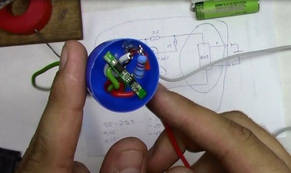
Solder the BMS scarf to our circuit. We mount in the egg from the kinder. Glue with thermal glue.

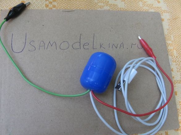
The wires are brought out. We mount crocodiles and the device is ready.

The LED indicates the charging process. Yellow - the charge is on. Green - charge is over

Detailed assembly instructions are displayed on the video.
7.3
6
6

Add a comment

    • smilesmilesxaxaokdontknowyahoonea
      bossscratchfoolyesyes-yesaggressivesecret
      sorrydancedance2dance3pardonhelpdrinks
      stopfriendsgoodgoodgoodwhistleswoontongue
      smokeclappingcraydeclarederisivedon-t_mentiondownload
      heatirefullaugh1mdameetingmoskingnegative
      not_ipopcornpunishreadscarescaressearch
      tauntthank_youthisto_clueumnikacuteagree
      badbeeeblack_eyeblum3blushboastboredom
      censoredpleasantrysecret2threatenvictoryyusun_bespectacled
      shokrespektlolprevedwelcomekrutoyya_za
      ya_dobryihelperne_huliganne_othodifludbanclose
72 commentary
Author
Actually, we are talking about the BMS board. Copy, do not copy. And what useful things have you explored, an article written, useful advice posted, mega home-made or otherwise. All that I wanted to say, I said.
Quote: popvovka
my 10 years of operating time down the drain (

What are the best practices - copying an indication circuit from a Chinese charge?
Author
So my 10 years of operating time down the drain (
I looked at the diagram again. I admit my oversight: indeed, the device is safe from any USB source. Charging will not go optimally (slowly), but safely. So, if the charging time and its fullness do not care, then you can apply. )))
popvovka, the internet is full of information on these boards, why rewrite? If you can’t find it yourself, I can throw a link. Just read and understand what you don't know about these boards. ;)
popvovka,
This means that the diagram is incorrectly written.
Author
So write a competent article on this subject, what's stopping you? Maybe the lack of truthful data. I advise you to study how BMS works outside of the battery
For information, my early video
Author
At the end, green and lit))
And what about the tanning of the green light at the end of charging? Is everything right?
Maybe it didn’t explode. As for performance degradation, how can you say that? From a weak source (less than 0.7C) there really will be nothing, except for undercharging the battery, which, of course, is safe. But this does not mean that you can recommend your scheme for repetition. Moreover, the name is doubly incorrect, and you don’t know the principle of the BMS:
The current will not exceed, for this there is a BMS board.
Author
I will say briefly. Studied and tested for almost 10 years. Not a single battery in all this time was harmed!
Quote: popvovka
The current will not exceed, for this there is a BMS board.

Before declaring this, familiarize yourself with the purpose of the BMS and its functions.
Author
Connects to any source with USB. The current will not exceed, for this there is a BMS board.
By the way, the display circuit is borrowed from the Chinese charge.
Author
Is the BMS board for fun in the battery all built in?
USB is connected to the memory, as in the diagram. Adjustable current memory? Then what's the point of this nonsense? As said earlier, as an indicator? In the magazine "Radio" for 89-90gg (I do not remember exactly) there is much cooler for SC batteries. But there are calculation formulas for resistive and capacitive circuits. Even simpler and even cooler, and with a charge indication. Calculate for your battery and use.
How can at the end of the charge (when the current is minimized) burn green if the transistor is closed?
Quote: popvovka
And what about the USB charger, which is used universally not standard?
Yusb pc or laptop also called a charging connector?

1. Any source with a USB connector is standard only in voltage, but their currents are different.
2. I did not say anything about the standard memory, this is your speculation.
3. And now - the main thing. A USB source is not a charger, but a voltage source. The charger for lithium batteries should (if you have a BMS, for example) also have the function of adjusting the charging current depending on the voltage on the battery. This is not provided for you, which leads to a reduction in battery life.
Author
I still can’t wait to see your super-duper designs, otherwise all the comments, comments ...
Here the error closed. During the charge, both burn, forming an orange.
Author
And what about the USB charger, which is used universally not standard?
Yusb pc or laptop also called a charging connector?
In the title
Cool charger for 18650 from trash
the first two words do not correspond to the presented product: “cool” - only to attract attention, this device is not a charger, it is only a charge current indication circuit, which still needs a charger (moreover, not what the memory is called for, but really - charger).
1. What is cool?
2. What are we feeding from?
3.
Yellow - the charge is on. Green - charge is over
But according to the scheme - the opposite.
Author
If you have questions, we ask, do not be shy)

We advise you to read:

Hand it for the smartphone ...