» Electronics »Automatic circuit breaker

Automatic circuit breaker


One late autumn evening, I broke into the country (tired of my wife, probably). He turned on the switch and the light in the living room - a bright flash, and all the lamps (ordinary incandescent) burned out. I went to look for a multimeter. Bah, I have 285 V in my network! And if "0" were burned out at the substation, all 380 V would be mine! What would happen if I didn’t turn off the switch and leave the refrigerator or TV plugged in? In the best case, they would have burned down. And so a fire could occur due to a short circuit. So he sat all evening by candlelight and ate canned food warmed up on a Bumblebee (yes, I still have such a device). The problem somehow needs to be solved.

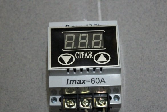
I arrived in the city the next day. I knew that there were devices that cut down the network with increasing voltage. I did not like them at the cost of up to 6,000 rubles. (the price depends on what current they are designed for). In addition, the relay is their executing element - my electronics in the country, while they will turn off the energy.

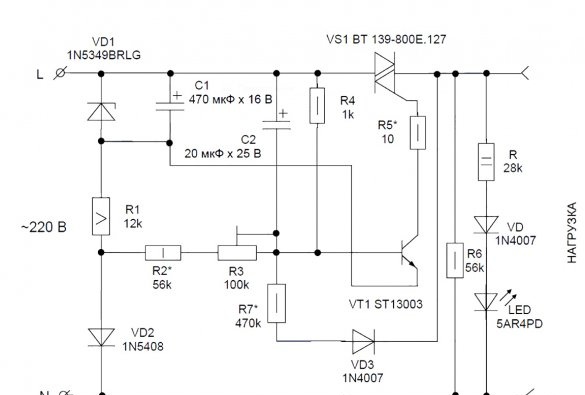
And if you make yourself such a device based on a high-current triac? I rummaged through the net and found a suitable scheme. I did not like only that the KU208G triac was used as a key. They are very capricious in work, and in terms of power they do not suit me. I decided to replace it with BT 139-800E.127 (it is inexpensive and reliable). At the same time, you need to change the control transistor to ST13003 (which is more suitable for the parameters) and the zener diode to 1N5349BRLG. The resistance power R1 must be increased to 5 W, and the diode VD2 should be changed to 1N5408. Then you can squeeze about 10 kW, which is what I need.

The key element is the triac VS1, the control electrode of which transistor VT1 is supplied with a negative voltage. Resistor R5 is used to limit the current. The reference and control voltages are removed from the parametric stabilizer VD1-R1-C1. In a chain with it is a diode VD2, which supplies the control voltage, which varies depending on the voltage in the network.

When the voltage in the network (and, accordingly, on the resistive divider R3-R4-C2) reduces the emitter current of the transistor to zero, the triac closes. Positive feedback, built on the R7-VD3 chain, provides reliable switching of the transistor. The current through feedback is summed with the current at resistor R3, increasing the voltage at the divider R3-R4-C2. This reliably turns off the transistor and, of course, the triac.

The value of the resistor R3 determines the trip voltage.The value of resistor R7 is the spread between on and off.
To indicate the operating mode at the input and at the output, I decided to put two LED chains. The output chain will also load the triac at idle (then R6 can be excluded).

What is necessary:
1. Soldering iron.
2. A set of electronic components + printed circuit board.
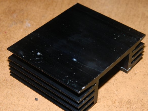
3. The radiator for the triac.
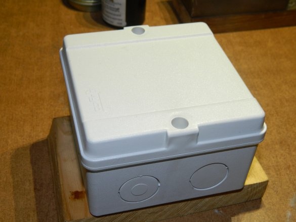
4. Housing for the product.
5. LATR to configure the circuit.
6. Screwdriver, tweezers, scalpel, side cutters.
7. The drill.
8. Multimeter.

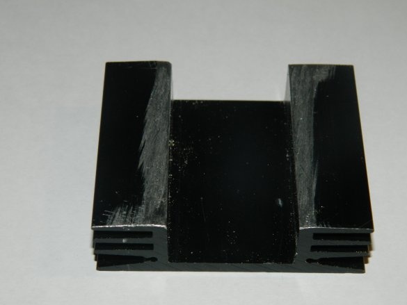
Missing (5-watt resistor R1 and triac VS1) I bought in the store "Chip and Dip" for 50 rubles. The remaining parts were in stock. To cool the triac used heatsink HS 304-50. Its area is more than enough. Yes, I bought it in Castorama for 57 rubles. mounting box for the case of the future device.


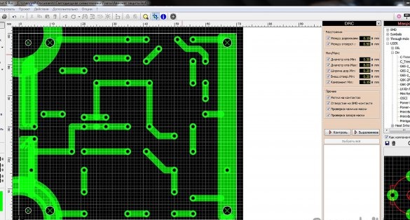
I drew a printed circuit board in the program Sprint-Layout 6.0.

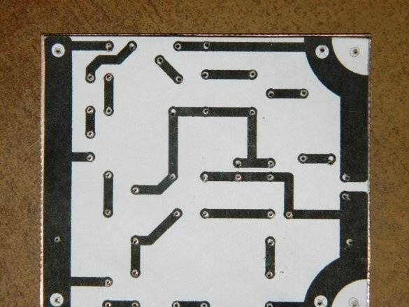
He printed on an inkjet printer on plain paper mirror, then glued to a piece of fiberglass, suitable sizes. Previously fiberglass was treated with fine sandpaper with detergent Seth. With a Ø1.0 mm drill, I drilled holes for parts and technological holes and washed paper off with warm water.

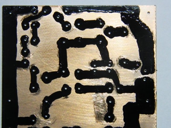
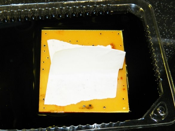
He drew a printed circuit board with a special marker. Then he placed the board in a solution of ferric chloride for half an hour.

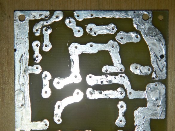
Chloric iron is hardly washed off from the hands, so I made a kind of pen from masking tape. Acetone washed off the paint. I drilled the technological holes to the required diameter and soldered the board conductors with a soldering iron. I finished with the board.


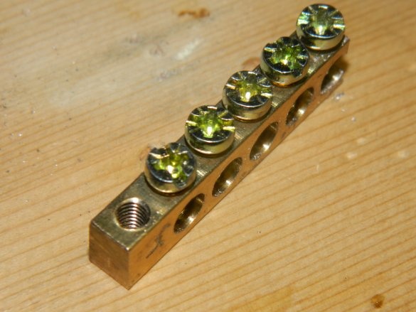
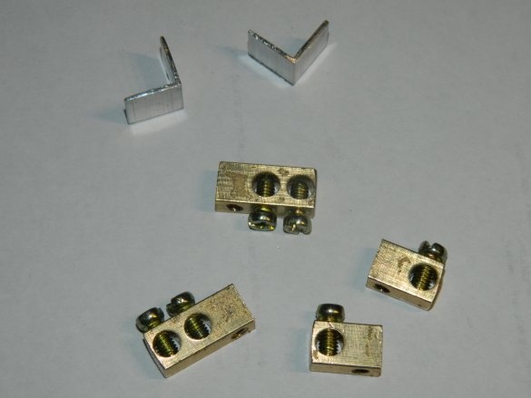
The extreme parts of the grounding bar, where there are perpendicular threaded holes for mounting, came up as contactors. I sawed two corners to fix the board to the radiator. The radiator did not fit literally 2 mm into the case. With a drill I cut from two sides on the shelf. With an area of ​​230 square meters / mm, this is not critical.


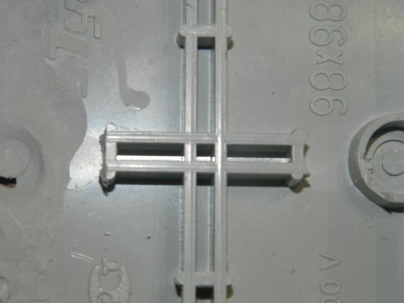
I removed tides from the bottom of the mounting box with a drill that only interfered.

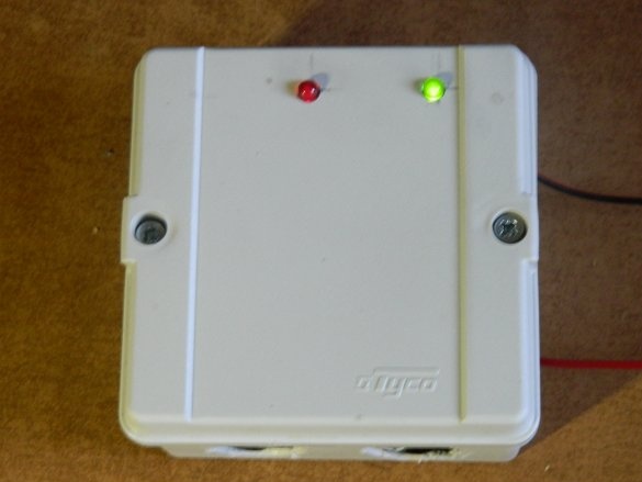
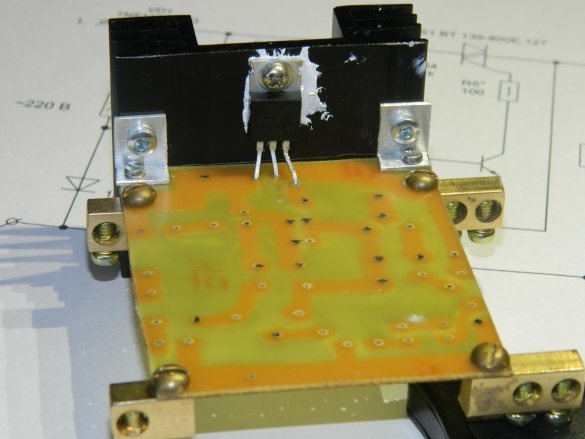
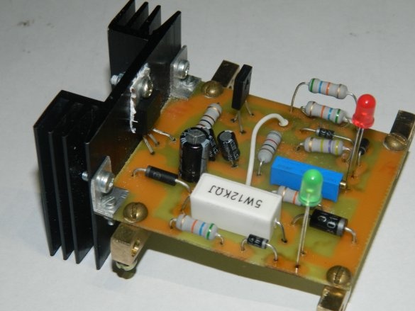
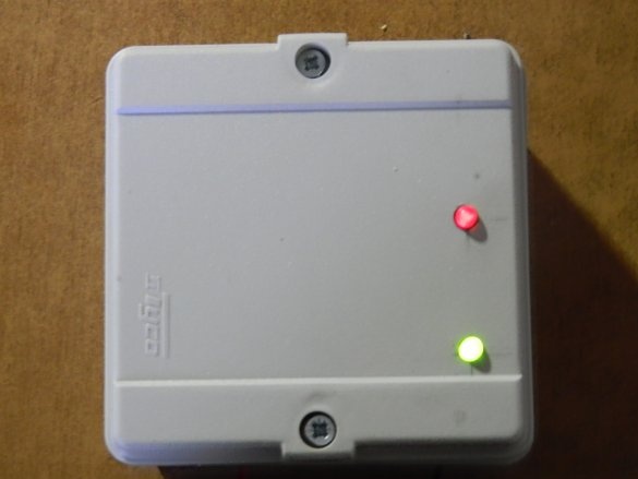
I fixed the board to the radiator at two corners, and I calculated so that the indicator LEDs could exit through the cover. The triac was mounted on a radiator through paste KPT-8. The base 2 of the triac is connected to the cooling pad, so the contact of the radiator with the input / output contactors is fraught with a short circuit, as well as with the conductors on the board.

Then soldered the remaining parts. Instead of a 20 μF × 25 V capacitor (I just didn’t have it), I put two 10 μF × 50 V in parallel. I soldered the indicator chains so that the LEDs slightly exited through the pre-drilled holes in the cover.

R3 set the average value of the protection threshold. I connected the LATR and the multimeter and made a more fine-tuning. R5 replaced with 10 ohms for the stability of the triac.

I did not have a 28k by 2W R resistor for the output chain with a red LED. I put two in parallel at 56k per 1 watts. The input circuit with a green LED does not affect the operation of the circuit, therefore it is not shown in the circuit.

At a voltage of 180–250 V, both LEDs light up. When the voltage rises to 255 V, the triac turns off the phase (only one green LED is lit). The triac again applies the phase to the load when the voltage drops to a level of approximately 235-240 V.


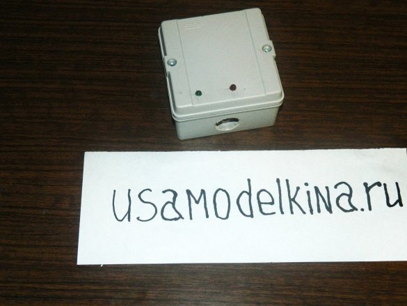
Dimensions of the structure are 60 x 90 x 90 mm. All openings in the mounting box have been specially opened to improve circuit cooling. Spent on the device a little more than 100 rubles, but several days of work. I think it's worth it!
8.6
9
8.2

Add a comment

    • smilesmilesxaxaokdontknowyahoonea
      bossscratchfoolyesyes-yesaggressivesecret
      sorrydancedance2dance3pardonhelpdrinks
      stopfriendsgoodgoodgoodwhistleswoontongue
      smokeclappingcraydeclarederisivedon-t_mentiondownload
      heatirefullaugh1mdameetingmoskingnegative
      not_ipopcornpunishreadscarescaressearch
      tauntthank_youthisto_clueumnikacuteagree
      badbeeeblack_eyeblum3blushboastboredom
      censoredpleasantrysecret2threatenvictoryyusun_bespectacled
      shokrespektlolprevedwelcomekrutoyya_za
      ya_dobryihelperne_huliganne_othodifludbanclose
207 comments
I am well acquainted with these documents. However, I will tell one story for thought.In general, I learned that thanks to outdated regulatory documents, we confuse colors when my company was offered to redo the wiring in the building of one serious three-letter government structure. The employees of the company that worked there before us did everything in principle normally, except that the project did not have color decoding of the conductors and they did it “as they knew”, that is, they divided the zero with blue. They were not embarrassed that 2/3 of the GOST VVG cable at this object did not have a conductor in blue insulation at all, so the guys experimented and led zero black, since it was. For them, we redid only the commutation and made zero white everywhere. In the same place, in addition to the machines with colors (this is just an indication, not a design), I also saw a three-phase climate control unit on the patch plate that said "L1, L2, L3 - COLORS. N - WHITE." Given the status of the organization, absolutely everything used was pipets as officially certified. So we now have only the reluctance or laziness of the "bodies" to bring regulatory documents to modern standards.
Sensitivity to current also depends on the emotional state and salt balance of the body. And appearance and sexual characteristics have almost nothing to do with it. I already talked about one of my acquaintance. He is, as they say, healthy as a bull, and looks like an adult bull, but he is thrown away by touching the terminals of a car battery. I can imagine what could happen to him if he touches 220. As for the current of 30 mA alternating current, this is not at all a small current, but a very dangerous one. Studies have established that for humans, AC current with a frequency of 50 or 60 Hz 100 mA is fatal. In fact, it also depends on the duration of exposure. And 50 mA can be fatal. The fact is that an alternating current of this frequency causes muscle cramps and a person is often not able to free himself. Also, the action of the current depends on the path of its passage. The most dangerous are arm-arm and arm-leg. Therefore, it is advisable to use a 10 mA RCD. But often such "sensitive" RCDs are not set, due to false positives. I will explain. I used to live in a rather old panel house. I decided to try the RCD on 10 mA. But it periodically worked for no apparent reason. I had to give it up. And the reason was revealed later, when the light in the bathroom stopped turning on. He began to understand and found out that the wiring in the bathroom wall was damaged. I determined the approximate location of the damage. Gouged and found that the aluminum wiring was fixed with a nail. Over time, in conditions of high humidity (neighbors were systematically flooded from above), a leak went to the wall through the damaged insulation and nail. This caused a protection trip.
Whether it’s decent or not - the feeling of this depends on a number of reasons: age, gender, skin condition, health status, etc. You are an adult strong man with rather rough skin of your hands - you were stabbed. A cold schoolgirl girl shibanet much stronger. The current is the same - the effect is different.
Quote: R555
Many times I came across a ball screw with two cores, the insulation of both is white. Well, where in this case + and -?
ShVVP cord is not intended for laying in electric networks. Its ends are hidden in the plug and the device that connects with this wire, so the color of the insulation of the wires does not play a role.
Valery
He jerked his hand, rubbed it ....
Inspired by: What is step voltage? This is the tension between the legs when you take the bare end. xaxa
And 15 years ago it was possible to plug the plug into the outlet only in a certain position ????
And further. Take a voltmeter and measure the voltage between any phase and zero. And then between any two phases. Question. What voltage was Ilyich's bulb on?

And why do you take for the postulate that "many phases = this is a three-phase network with a voltage of 0.4 kV" ???? Phases are also different!))))
Valery, why is the automatic machine in the modern apartment panel dual? What, also 2 phases commutes? xaxa
They are installed ONLY as introductory !!! That is, the second connector simply performs the function of a switch!
The main thing is why they are produced - for installation in networks in which the voltage to the working one is reduced (increased) using a transformer! (Figuratively speaking, at the exit from the trance, "there is no phase or zero", therefore it is necessary to protect both lines.
Valery, and why in a modern apartment panel the machine is dual? What, also 2 phases commutes? xaxa

And further. Take a voltmeter and measure the voltage between any phase and zero. And then between any two phases. Question. What voltage was Ilyich's bulb on?
And in a two-wire system in a similar situation, it will work if a person touches the case and the leakage current through the person exceeds the norm,

So I described this when I said that "RCD will detect a leak through the" terila "already.))))))))
kill will not kill, but fucking decently.

Not decent. It is checked twice by me personally)))). The RCD (30 milliamps) worked so clearly that I thought that it was I who simply pricked myself with a dead wire. He jerked his hand, rubbed .... And only then I realized that this wire was connected, and that is why the light went out ...))))))
Valery, and why the color television "Record VTs-311" on a network block 2 fuses (in both wires one at a time)? What, 15 years ago, there were 2 phases in the outlet too? xaxa
This is not the old !!! This is when they appeared in double isolation! (More often - in blue))))
And in even more distant times, there was wiring from twisted wires of the same color on porcelain rollers. And to understand where there is phase and zero was impossible. And the phase indicator, of course, was not. And Ilyich’s bulb still glowed in the hut, on the drum, where the phase is and where is zero.

Most interesting, I saw such wiring (acting!) Several years ago, not in a remote village, but in a large city at the same factory.

There was no zero then !!! IT WASN'T !!! !!! ... Two phases were then fed !!!
That is precisely why there are two traffic jams on old meters !!! (Why is there a fuse at zero ???) (Recently, somewhere around here I remembered about it)
Many times I came across a ball screw with two cores, the insulation of both is white. Well, where in this case + and -?

I have never met a “shavepashka” not with blue and brown! .. Now, right now (I'm in the basement) I looked at all the pieces ... Everywhere - blue and brown! And in all sections.
By the way, they are marked GOST7399-97. And on yours what? ... Really, have you introduced different standards?
Clarification. It should read "... the combined conductor PEN, which in the shield is divided into N and PE."
Quote: R555
What the hell is bus B connected to the end of the winding of a DC power supply?
If you read the indicated clause of the EMP, then you will read not “direct current”, but “alternating current”.
Quote: R555
And also I know that to the full extent, almost no one is observing it.

If your company spits on norms, then this does not mean that it is so - everywhere.
What described Nruteris a grounded neutral. If a separate phase comes, separately zero, separately PEN, then this is a variant of TN-S, which is not very common due to the high cost. The most common version in the modern version is the TN-C-S, when the phase comes and the combined N-PEN conductor, which in the shield is divided into N and PEN.
In everyday life, isolated neutral, as a rule, does not occur.
Nruter
You killed me ...
Ofigel himself, when at our factory I saw 3-phase motors connected by a 3-core PVS, colors: yellow-green, blue (blue), white !!! When asked about compliance with the PUE, the power engineer said: "Put your PUE in your ass!" xaxa
R555
Why are you so disrespectful about my knowledge ... What the hell is bus B connected to the end of the winding of a DC power supply? What is the winding? Where?
In PUE !!! yes
Quote: Nruter
Easy to learn. If the neutral wire that came through the cable from the TP inside the shield is connected to ground, then this is a circuit with a grounded neutral. In the private sector, it is practically not applied. If inside the shield there is a separate ground bus (bare bus, yellow-green wires on it) and a neutral bus (blue bus, blue wires on it), then this is a circuit with isolated neutral. It is to this bus that pin N is connected to the RCD.

So this definition is wrong?
That you are so disrespectful about my knowledge. Of course I know what PUE is. And also I know that to the full extent, almost no one is observing it. I am sure that if you look at the shields mounted by you, there will be many violations. It depends on who will check. For example, if I want, I will find violations xaxa

And about marking wires with direct current, they generally wrote nonsense. Many times I came across a ball screw with two cores, the insulation of both is white. Well, where in this case + and -?

And further. What the hell bus B connected to the end of the power supply winding permanent current? What is the winding? Where?
Quote: R555
Regarding the fact that the phase is a blue wire, I want to say that I also connect DC power wires. For example, ballscrew - blue is a plus.

You killed me ...
Read the PUE (if you know what it is)
1.1.30. The alphanumeric and color codes for the tires of the same name in each electrical installation must be the same.

Tires should be marked:

1) with alternating three-phase current: phase A buses - yellow, phase B - green, phase C - red;
2) with alternating single-phase current, bus B connected to the end of the power supply winding is red, bus A connected to the beginning of the power supply winding is yellow.
Single-phase current buses, if they are a branch from three-phase busbars, are designated as corresponding three-phase current buses;
3) at direct current: positive bus (+) - red, negative (-) - in blue and zero working M - in blue.

After your statement about the blue plus, I have no words.

And in general, this is not a forum of electricians. Here I’m not going to argue with anyone, although I have a 5 group of up to 1000 V and above. I serve any electrical installations, but more often 6 and 10 kV.
And in even more distant times, there was wiring from twisted wires of the same color on porcelain rollers. And to understand where there is phase and zero was impossible. And the phase indicator, of course, was not. And Ilyich’s bulb still glowed in the hut, on the drum, where the phase is and where is zero.

Most interesting, I saw such wiring (acting!) Several years ago, not in a remote village, but in a large city at the same factory. xaxa
R555
he argued that white is always a phase
In very distant times, in a two-wire system there were only 2 colors - black and white, white - it is always a phase! yes
2Dem PUE and GOST 31996-2012 "Power cables with plastic insulation for a rated voltage of 0.66; 1 and 3 kV. General technical conditions »to help you (and to all of us)! yes
Author
I made a similar device to a friend in the country. He is very satisfied! By the way, he has more than 10 A consumption (if you turn on all devices). Somewhere around 15 A. Holds the machine!
Quote: maximace
It turns out the circuit with isolated neutral?
Not. With earthed.
Quote: maximace
What are the features of such a scheme?
Do you want to rewrite the book here? And by the way, not one. ;)
Quote: maximace
I understand that a triangle is grounding.
Not certainly in that way. It will only become grounding when the electric laboratory issues a protocol on the compliance of the resistance with the requirements of the PUE. )))
Quote: maximace
They just told me that if the grounding is made too good, it can be grounded on you from neighbors in the case of, for example, a lightning strike.
They said it right, so too low resistance is also bad.)) However, most likely, it will not be too low on such grounding conductors.
I looked at your picture: this is not a designation, but just a design element, corporate identity - the color of the AV control knobs is not standardized by any standard. I would try to make the manufacturer so indicate the color of the entry point of the wires.
There are controls for which the color is normalized, in particular - emergency stop buttons, they should only be red.
Quote: Nruter
If inside the shield there is a separate ground bus (bare bus, yellow-green wires on it) and a neutral bus (blue bus, blue wires on it), then this is a circuit with isolated neutral.
Nothing like this! This is a neutral earthed circuit, variant TN-C-S. From the definition of “with isolated neutral” itself, it follows that the neutral can connect to the “earth” only through relatively high-resistance control and protection devices.
A commercially available device certified to have a designation that contradicts the PUE cannot.
And to teach others to do not according to the PUE is also impossible.
Learn the materiel: PUE-7 p.1.1.29, 1.1.30.
A protective conductor is not needed for operation. It is needed to increase safety when triggered.
Example. A leak appeared on the cabinet in the washing machine. In a three-wire system (if the leakage current is higher than normal), an RCD will immediately work. And in a two-wire system, in a similar situation, it will work if a person touches the case and the leakage current through the person exceeds the norm, that is, it will not kill, but it will beat decently.
Regarding the fact that the phase is a blue wire, I want to say that I also connect DC power wires. For example, ballscrew - blue is a plus. And I also teach my students. And since one uncle was older than me, he claimed that white is always a phase or a plus (if there is a constant current). And he punched himself in the chest like a male gorilla. And whoever did not agree with him about such a color designation of wires, with those he strove to fight, moron.

Apparently, his teachers were so worthless. I just wrote about our physics teacher. Also, when I studied at a vocational school, we have a teacher who teaches radio engineering and special materials, special technology, also did not differ in special knowledge. Yes, yes, I didn’t make a reservation, we had such objects there. I know many are dismissive of such schools. I even remember that GPTU was decoded as "Lord, Help the Dumb Settle Up." xaxa But in vain. Who managed to finish such a school could earn a living with bread and butter. And of those who graduated from the institute with a degree in radio engineering, half did not know how to solder and could not explain what the difference between a varicap and a diode was. And such an “engineer” had to be hired by profession. And they did not have the right to dismiss him for a year or more (I don’t remember exactly), even if he drank at work and truanted. One such "worked" in our department.

So, we at the school thoroughly studied the scheme of black and white and color TVs. And we demanded knowledge of the TV circuitry up to the appointment of EVERY detail! And I took and asked the teacher (without a second thought) what is an "antiparasitic resistor", they were in the circuit of a black and white TV. She began to hang noodles on our ears. Like, this resistor freely passes a useful signal, and the parasites on it die xaxa xaxa xaxa I repeat literally. This answer did not suit me.I read at home in one book about how such a resistor actually works. And at one of the classes voiced this. The teacher was embarrassed, blushed. Like a physicist, I didn’t call me to the board for 2 months. And then, suddenly, I’ll ask something else, “going beyond the framework” of the curriculum ...
Quote: Nruter
blue wires on it

But you should not be guided by this at all, especially when it is not correctly done. Now, even on vending machines and other devices, many manufacturers have already begun (and the others will start soon) to show in color that PHASE (L) is BLUE (single-phase) / COLOR (three-phase), and neutral (N) is WHITE. As an example, the first picture you get, but the principle is clear, even manufacturers are trying to reach you, not in the Stone Age, in order to confuse colors.
A SIP 4x16 cable is stretched from the pole. Three phases and zero. It turns out the circuit with isolated neutral? What are the features of such a scheme?
Quote: maximace
But phase three. How to find out which circuit?

Easy to learn. If the neutral wire that came through the cable from the TP inside the shield is connected to ground, then this is a circuit with a grounded neutral. In the private sector, it is practically not applied. If inside the shield there is a separate ground bus (bare bus, yellow-green wires on it) and a neutral bus (blue bus, blue wires on it), then this is a circuit with isolated neutral. It is to this bus that pin N is connected to the RCD.
Quote: Nruter
Everything is exactly the opposite. It is this triangle that is the grounding. And already from it comes a wire to the shield. Further, this wire diverges in the wiring. Grounding is.
RCDs can be installed without grounding.
Again, you need to consider which power supply scheme is single-phase, three-phase with an isolated neutral, three-phase with a grounded neutral

Maybe I wrote poorly. I understand that a triangle is grounding. They just told me that if the grounding is made too good, it can be grounded on you from neighbors in the case of, for example, a lightning strike. And what kind of system FIG knows. But phase three. How to find out which circuit?
Quote: maximace
Made a triangle. He was led to it from the shield by grounding.

Everything is exactly the opposite. It is this triangle that is the grounding. And already from it comes a wire to the shield. Further, this wire diverges in the wiring. Grounding is.
RCDs can be installed without grounding.
Again, you need to consider which power supply scheme is single-phase, three-phase with an isolated neutral, three-phase with a grounded neutral
More grounding. I get a cable to the site from the TP. Accordingly, I put the post. According to the specifications, he scored 3 corners of 2 meters. Made a triangle. Grounding led him from the shield. Well, further from the shield, grounding goes to the house. It is believed that I have grounding? Can I put RCDs and arresters?
Yes, I also say that grounding for RCDs is not "mandatory", but "very desirable." In any case, it will notice currents that "did not return to zero", but that went to the ground through the "terpule")))))
give me nitrogen
-come to me. There are two banks, I don’t know where to go. Father-in-law brought, back in Soviet times
Yes, he is being sold with such round drops. Almost the same way, I just lower the board into the solution of the same lemon, when the copper turned pink - into the bath. I also crawl along the bottom, then turn it over and wipe the excess with a swab (a piece of cotton wool on top of a sushi stick, gauze on top) directly in boiling water. It turns out a thin uniform layer over the entire surface.

These are two different alloys. Well, more precisely similar. Wood has a lower melting point. I personally like Rosa more, Wood has the peculiarity to oxidize (it gets dark and then nichrome does not solder to him) over time. You can’t do any boards for future use. In addition, it is toxic (cadmium in it).
I also plated the boards with the Rose alloy when I made boards in series.Now I don’t have it, but if I see by chance, I’ll definitely buy a bag or two. I had in the form of small round circles. By the way, it was enough for a long time. Personally, I was so tinged. "Bath" - a large can from under some kind of candy or cookies, I don’t remember. Water was poured into the jar, the alloy fell asleep (more precisely, it was refilled) because the consumption is small - tinning is a thin layer, not like a soldering iron. On a hotplate, water was brought to a boil, the alloy, as expected, was melted at this temperature. He took the board, wiped it with a cotton swab moistened with hydrochloric acid, washed it with water and lowered it into a jar. With a wooden stick, he drove the board back and forth for 10 seconds and pulled out with plastic tweezers. The quality of tinning is perfect, the soul rejoices. I somehow already showed my boards on the site. I bombarded them in this way. Do you also make or are there any differences in technology?
P.S. Some call this alloy a Wood alloy. It will be necessary to read whether this is correct.
Add about the RCD.
1. The operating current of the RCD must be 1-2 steps higher than the current at which the machine that protects this line will work.
2. RCDs are electronic and electromechanical. The latter are more preferable, since in some emergency situations they will work, but electronic ones will not. They can be distinguished in appearance by the symbol on the front side.
3. Contrary to the common misconception that RCDs operate only in a three-wire network, they will also work in two-wire, but in some cases it will be less efficient.
Yes, to be honest, I don’t care what is in production. In production, circuit boards in bathtubs melt the waves with molten solder, but at home I still prefer ROSE. And for nitrogen ... give me nitrogen, and I nitrate everything that gets on my eyes! From the T-shirt in which I sit, to the stool on which !!! smile
Here, I drew a diagram of how I’ve done it now (only automatic machines) and tried to insert a 3-pole UZO 3-pole. Take a look
Nruter
There is nothing wrong with the RCD
Explained clearly! Even I get it! goodgood
It is called a differential circuit breaker.

Hearing is more familiar to "difavtomat"))))
And I am a supporter of poisoning with ferric chloride, although, of course, I know about the method with peroxide. And I do not have spots, I work neatly. And in the board I drill a hole, I tie the thread and with it I manipulate. Hands are always clean, at least sit down to dinner at the table. ya_dobryi By the way, they are poisoned with ferric chloride in production, peroxide or nitrogen is not used there, at least where it was.

Nitrogen poisoned at one time, it was "fashionable". Poisons quickly, but a little gape and the board kapets. Yes, and very harmful (nitric oxide is released). I have not been interested in it for a long time, I think they stopped selling nitrogen in the store for some reasons.

We advise you to read:

Hand it for the smartphone ...