

To assemble such an apparatus is within the power of everyone, even those who are completely far from electronics, just need to solder all the details as in the diagram. Metal detector consists of two microcircuits. They do not require any firmware or programming.
Power 12 volts, it is possible from finger batteries, but better battery 12v (small)
The coil is wound on a mandrel 190mm and contains 25 turns of wire PEV 0.5
Specifications:
- Current consumption 30-40 mA
- Reacts to all metals no discrimination
- Sensitivity 25 mm coin - 20 cm
- Large metal objects - 150 cm
- All parts are not expensive and easily accessible.
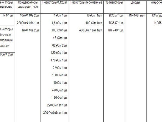
List of required parts:
1) Soldering iron
2) Textolite
3) Wires
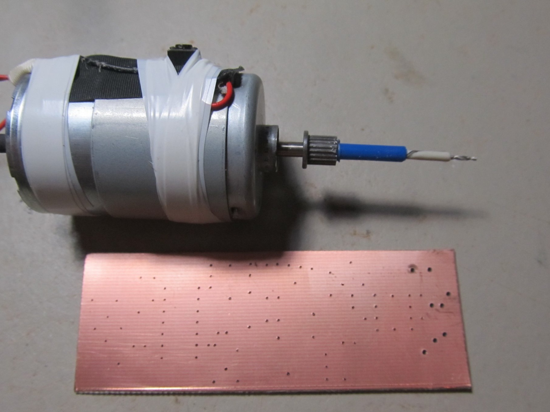
4) 1mm drill
Here is a list of necessary details.
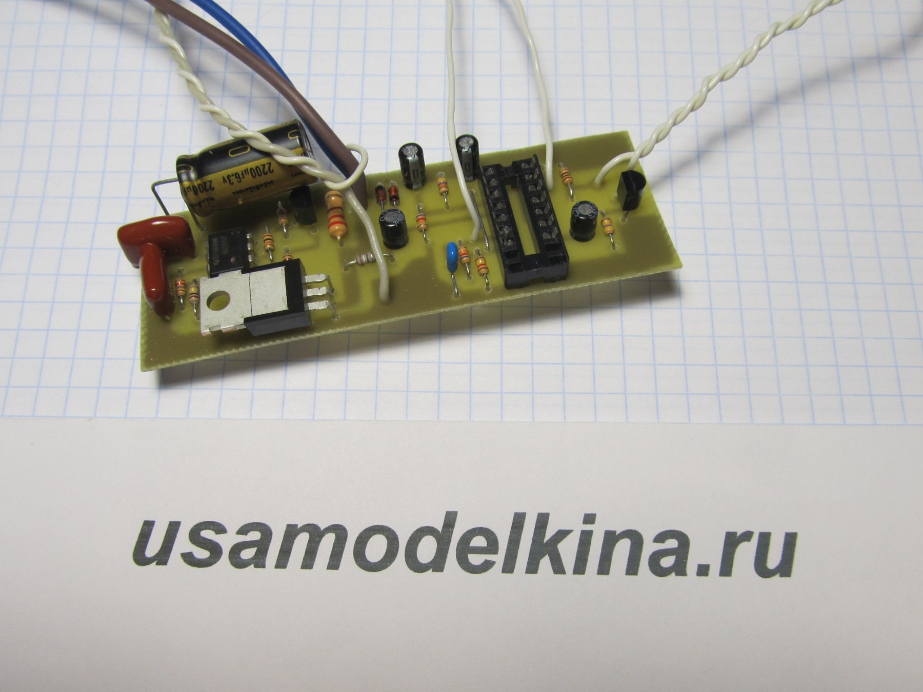
The scheme of the metal detector
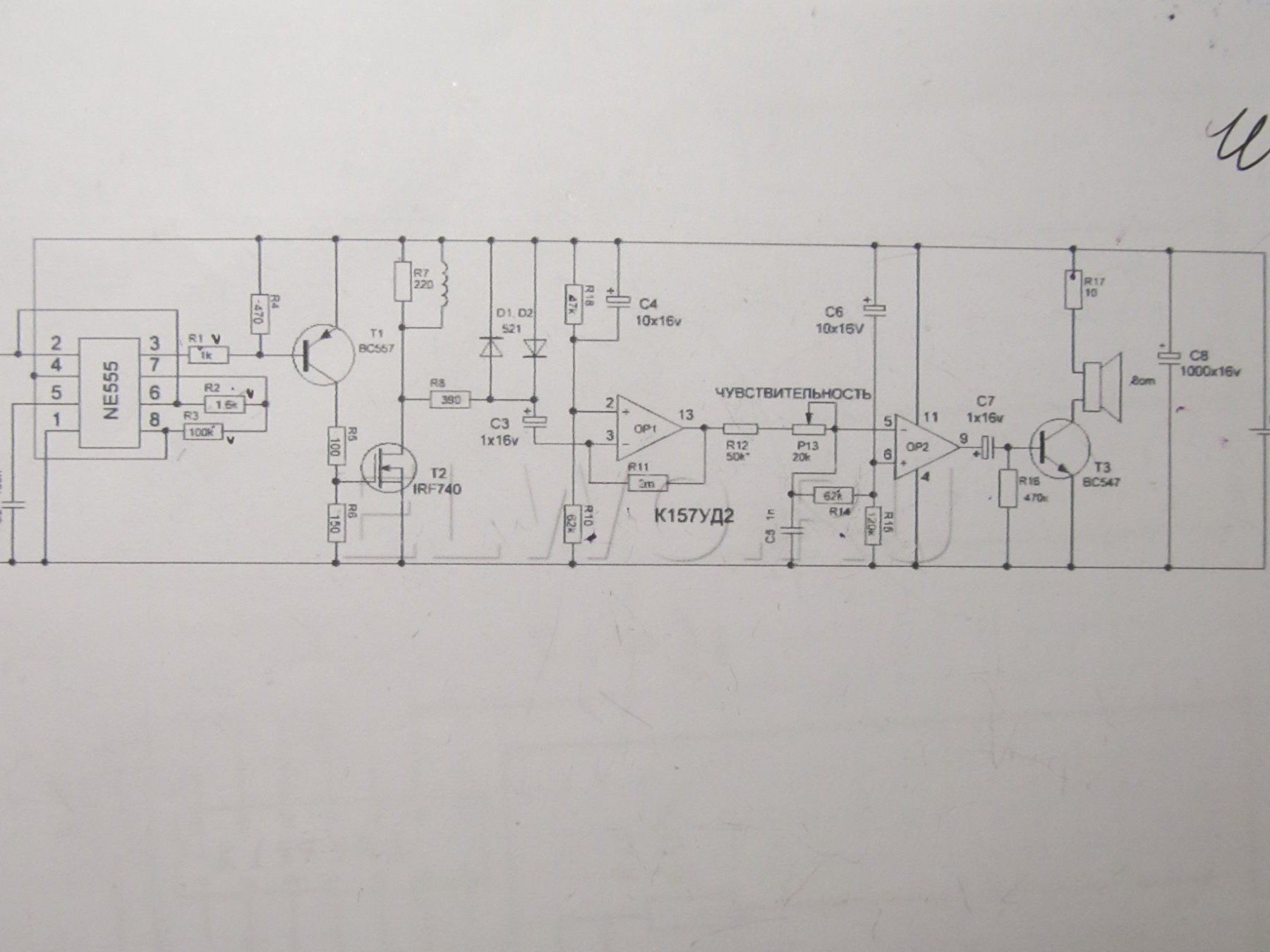
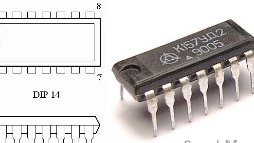
The circuit uses 2 chips (NE555 and K157UD2). They are quite common. K157UD2 - you can pick out the old equipment, which I successfully did
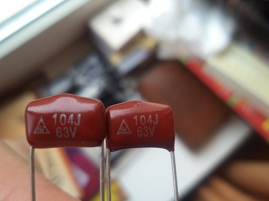
100nF capacitors must be taken with film, here we take as little voltage as possible
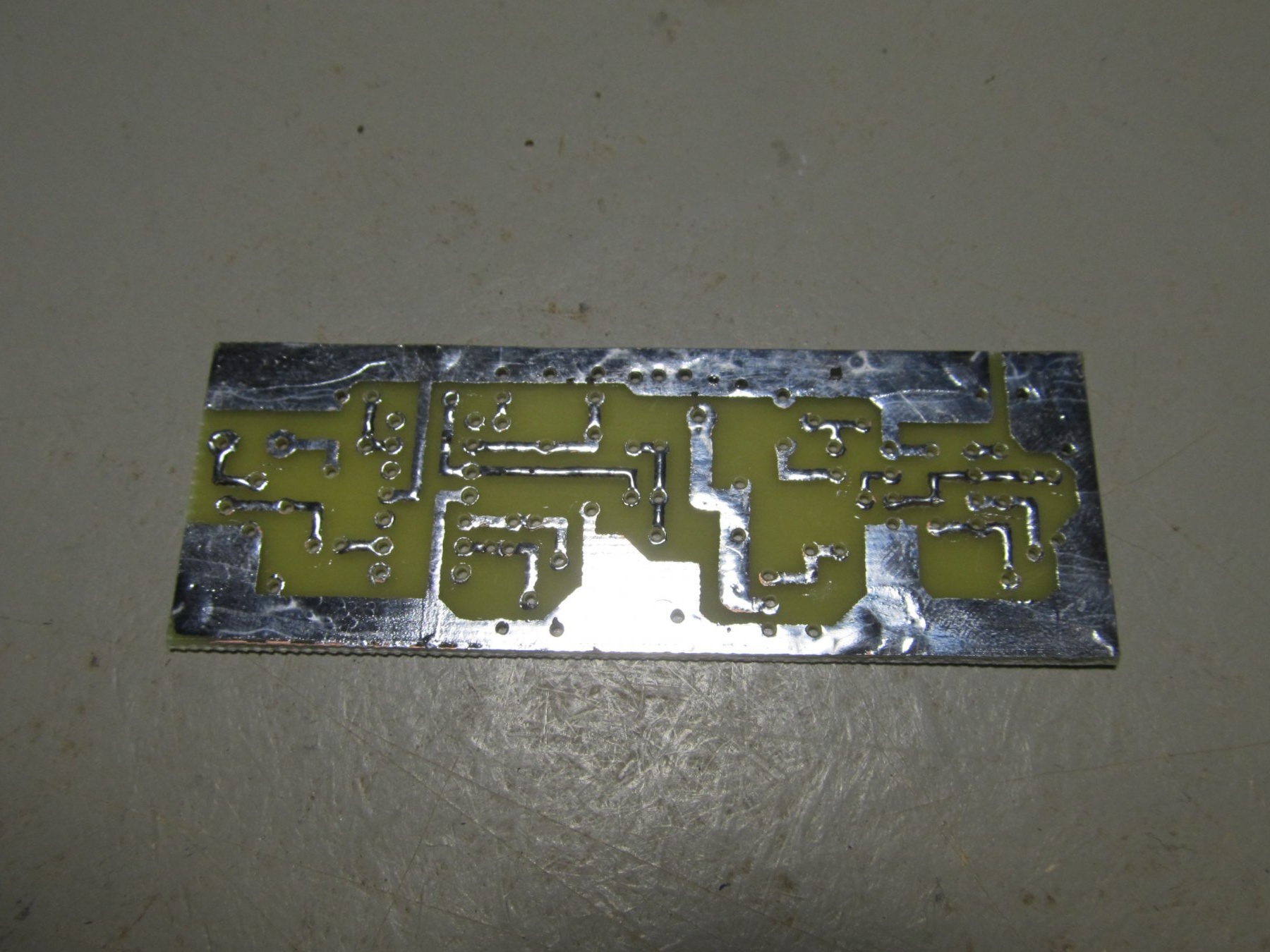
Print a board sketch on plain paper
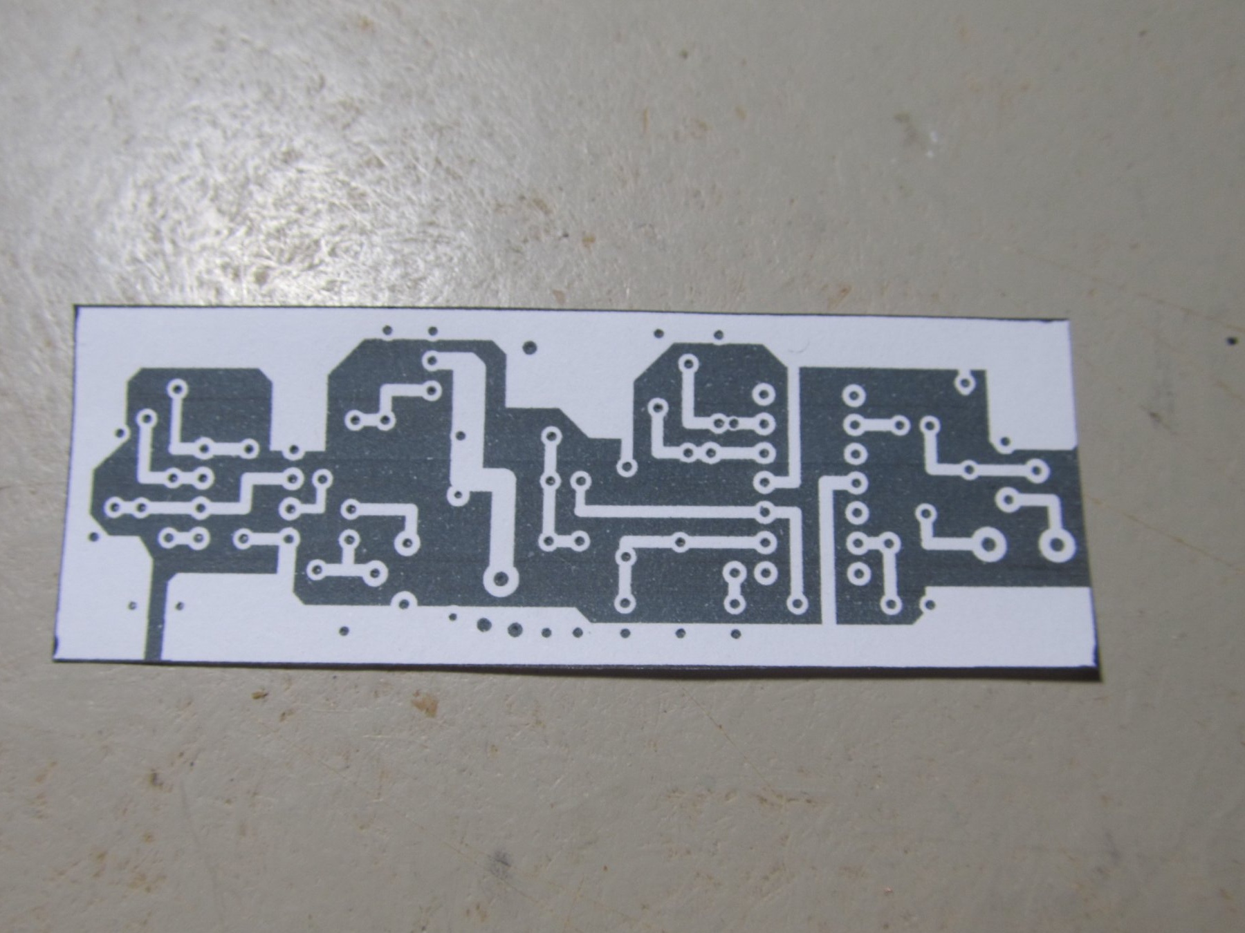
Cut a piece of PCB under its size.
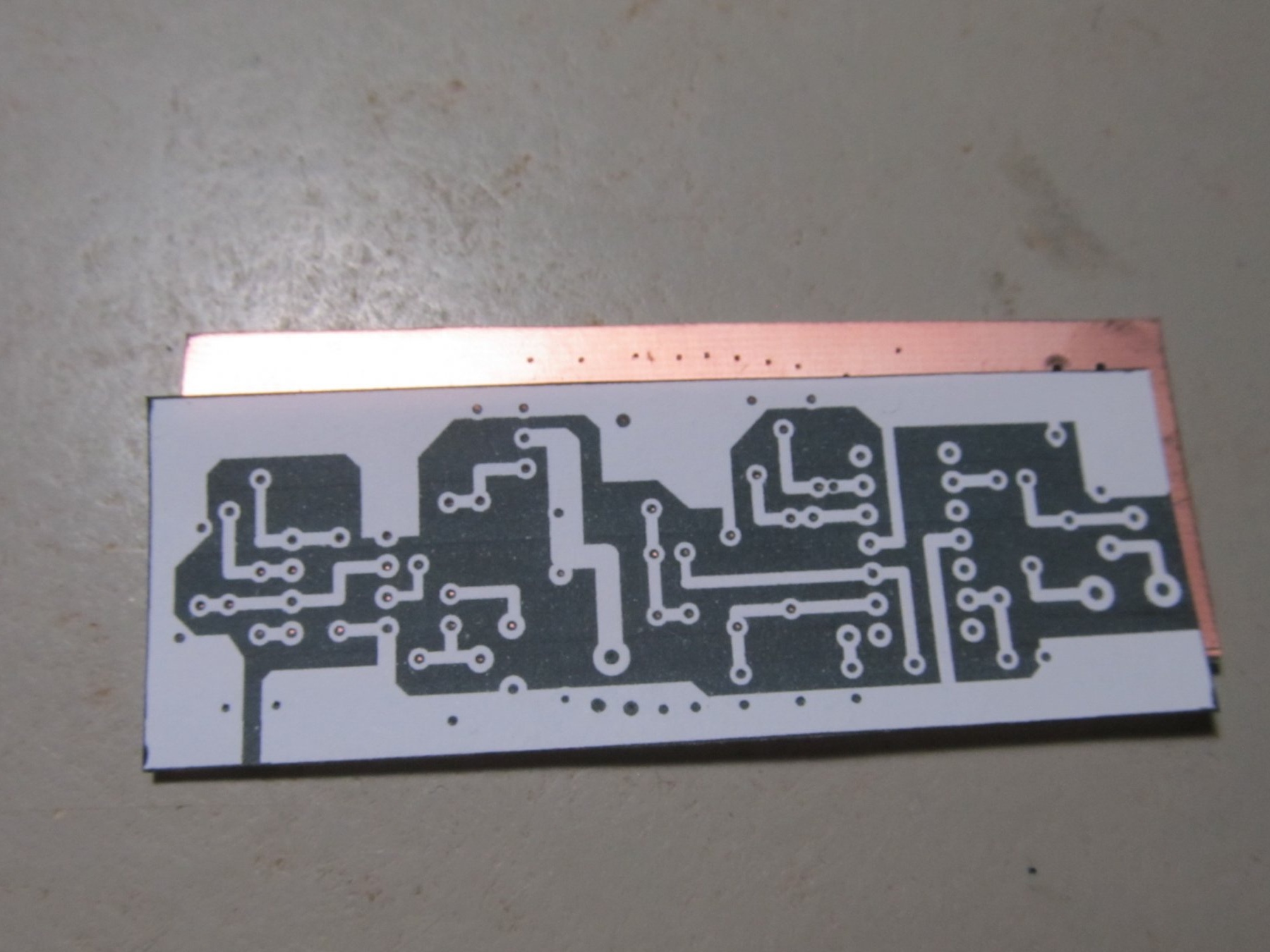
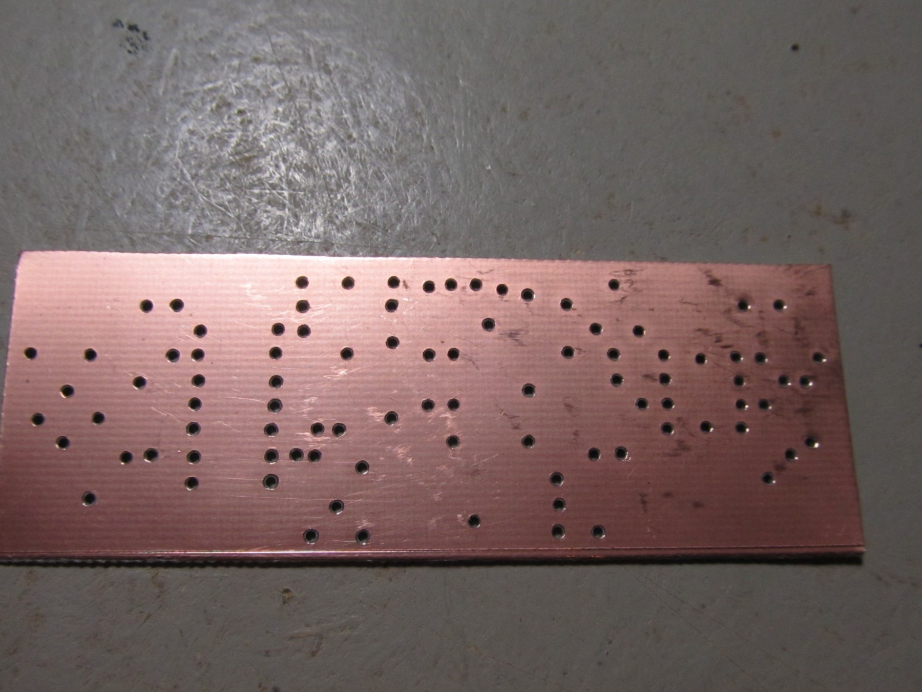
Tightly apply and push with a sharp object over the places of future holes
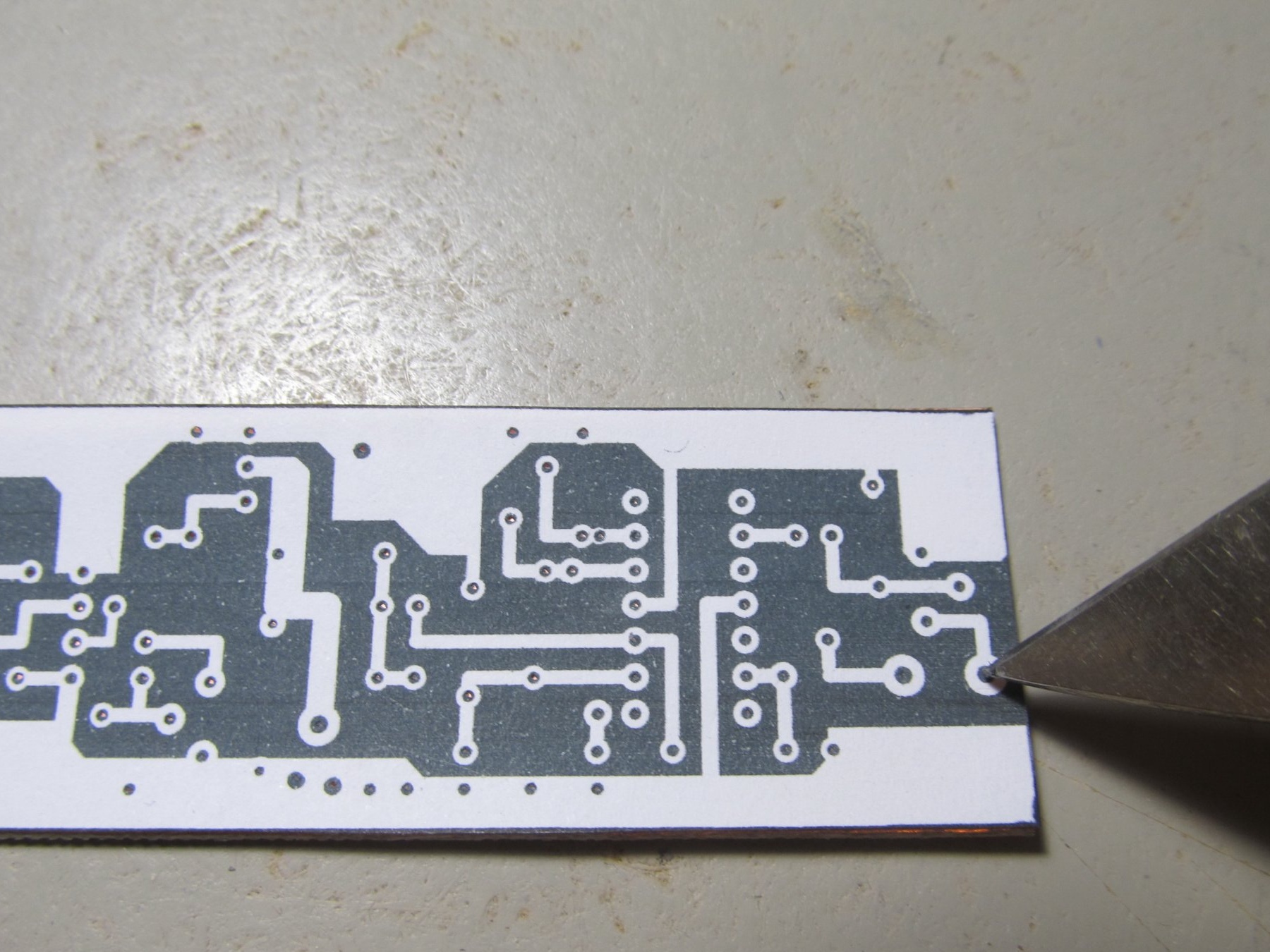
Here's how it should turn out.
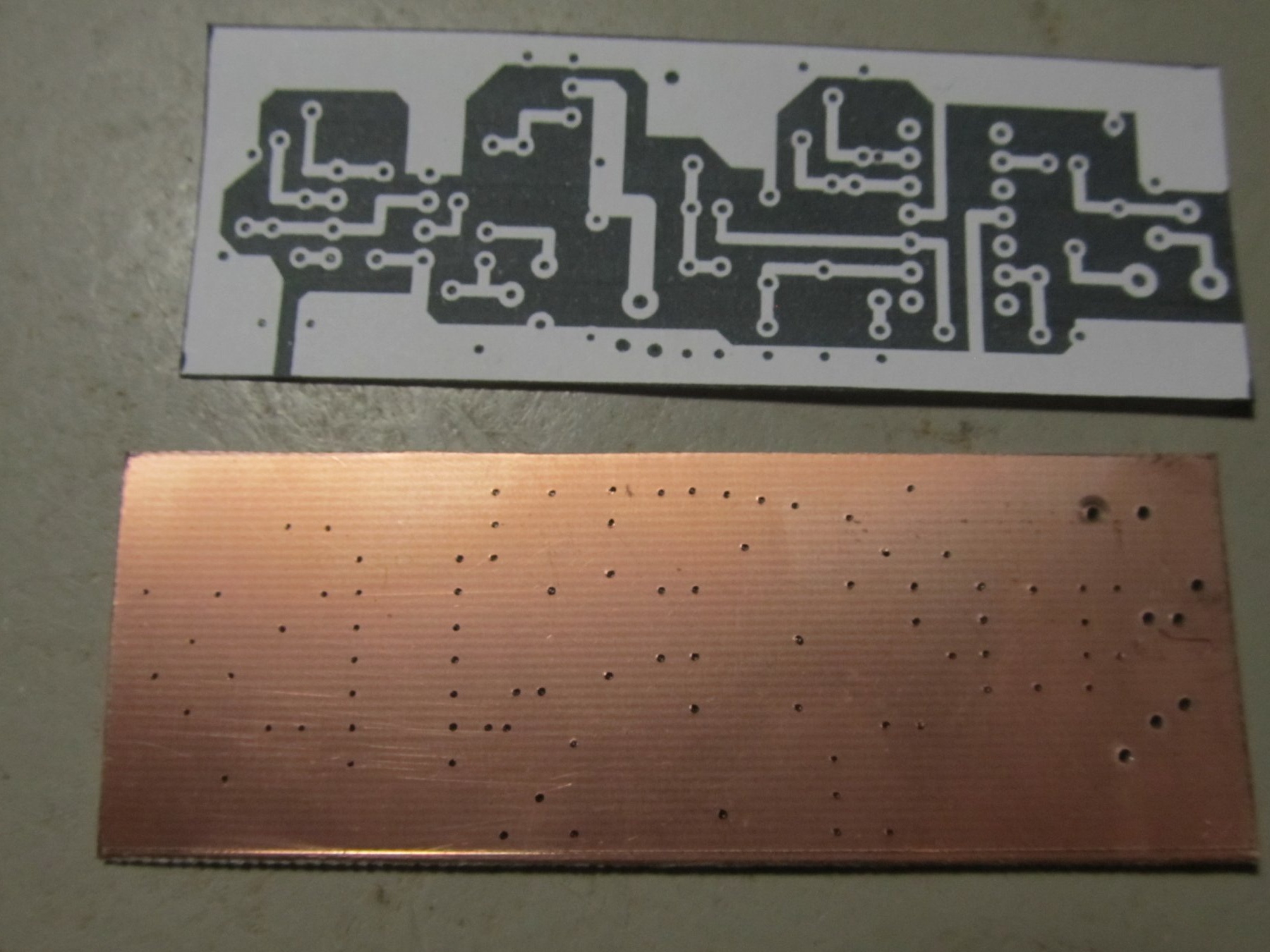
Next, we take any drill or drill machine and drill holes
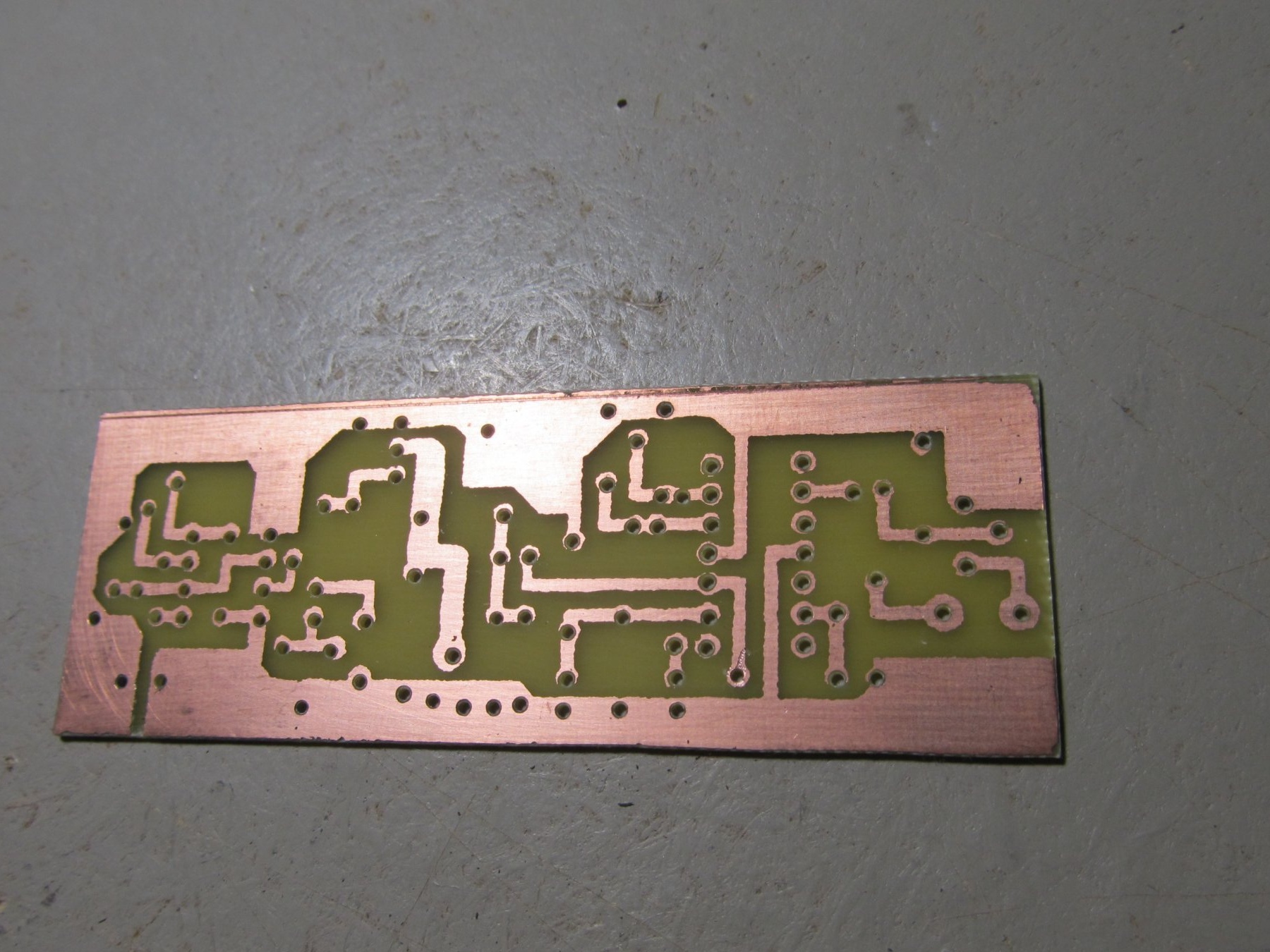
After drilling, you need to draw tracks. Can do it through photoresist, LUT or just paint them with Nitro varnish with a simple brush. The tracks should be exactly the same as on the paper template. And we poison the board.
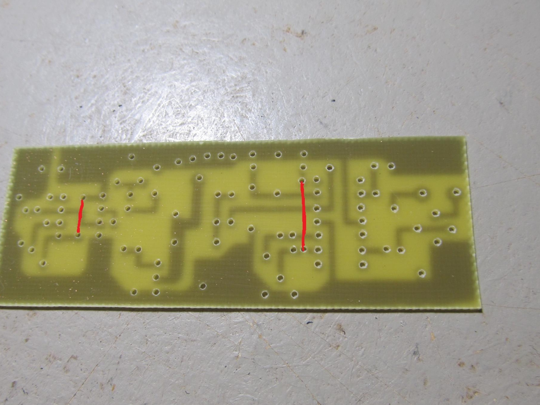
In the places marked in red, set the jumpers:
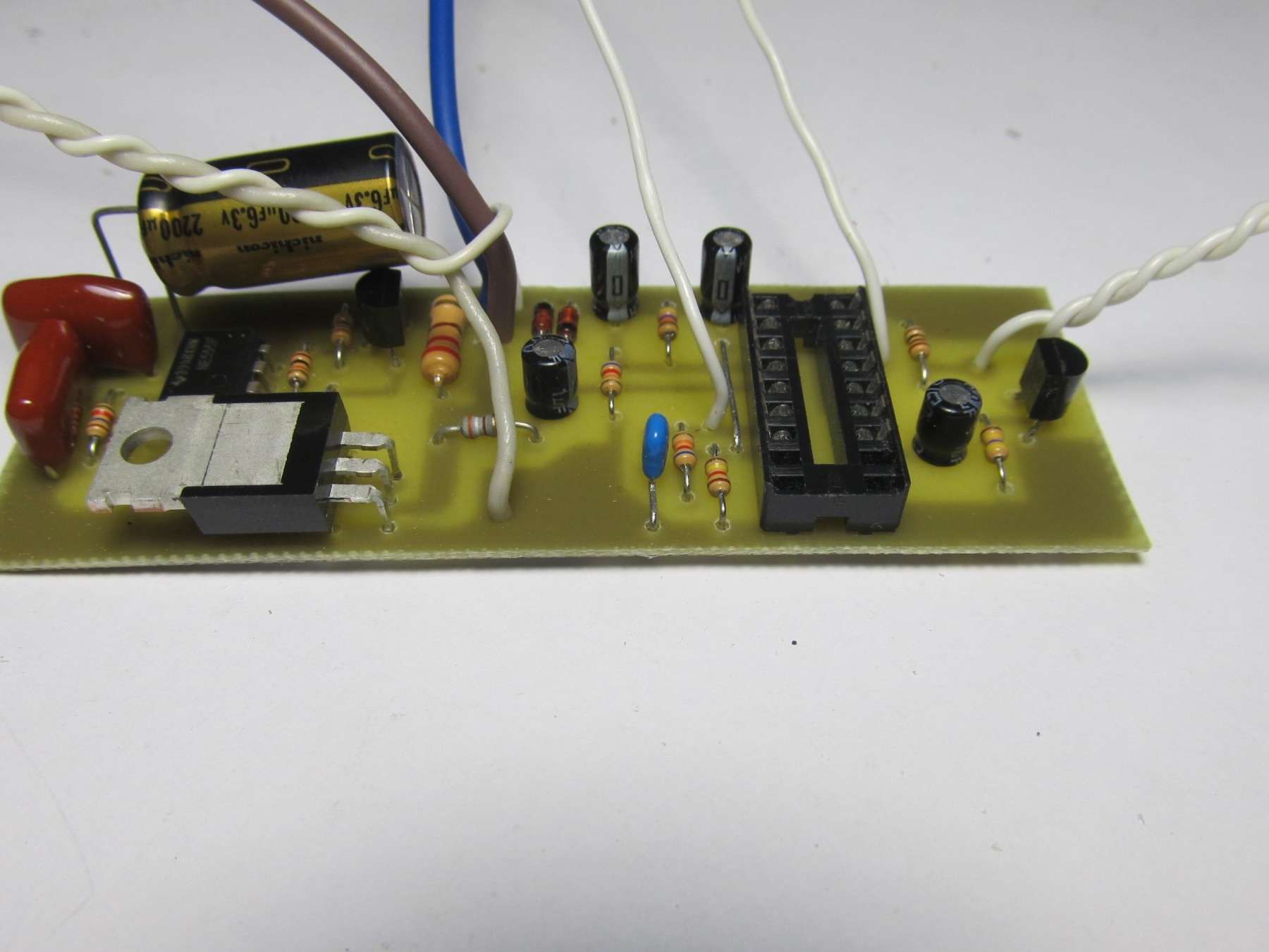
Next, just solder all the components into place.
For K157UD2 it is better to put the adapter socket.
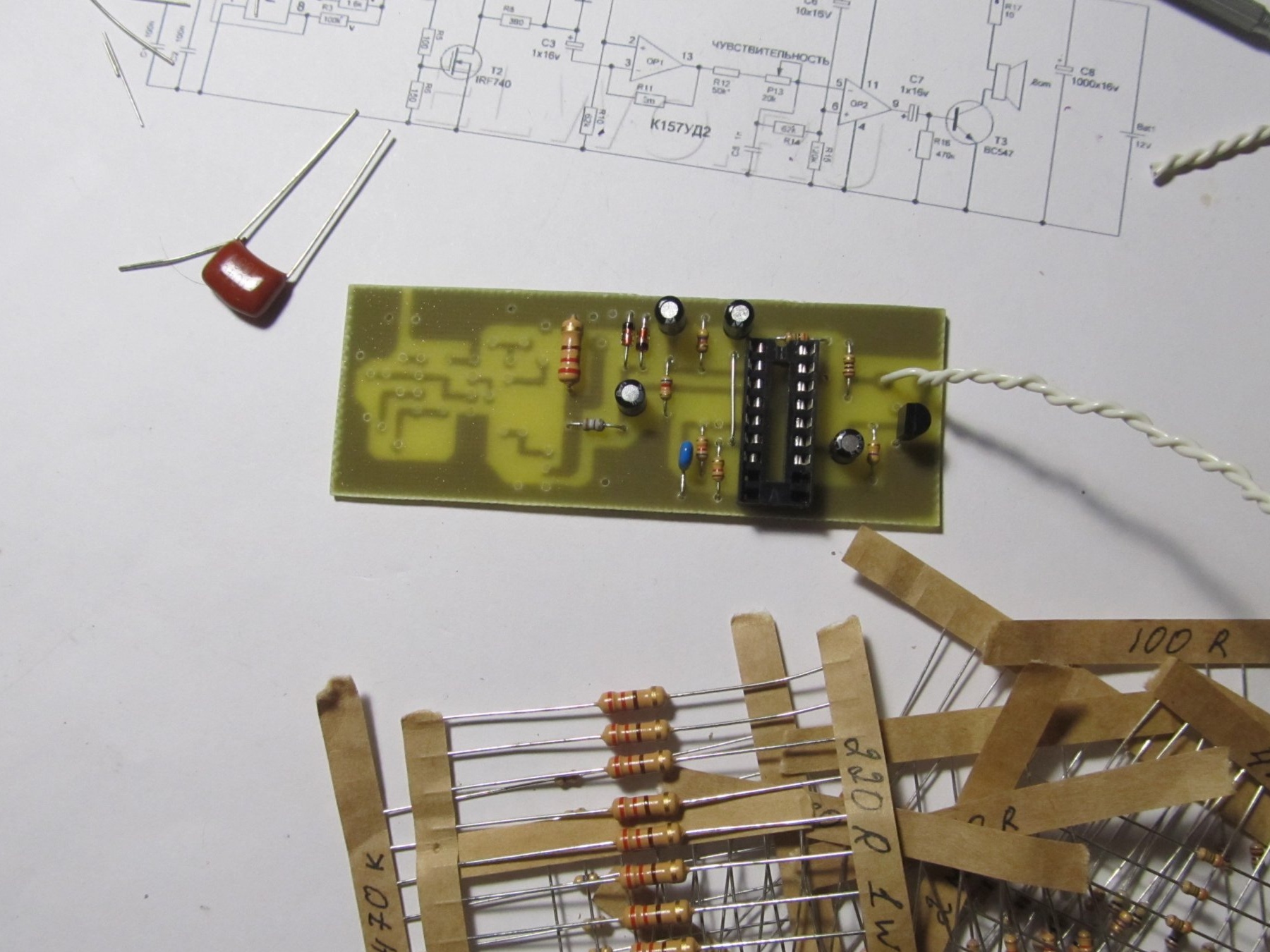
To wind the search coil, you need a copper wire with a diameter of 0.5-0.7 mm
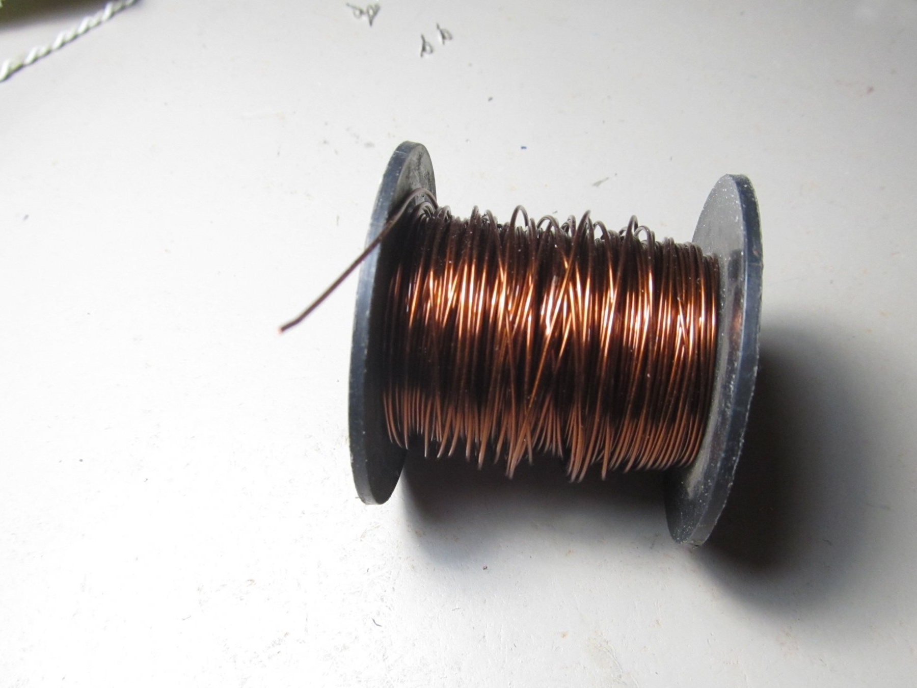
If not, you can use another. My copper lacquered wire was not enough. I took the old network cable.
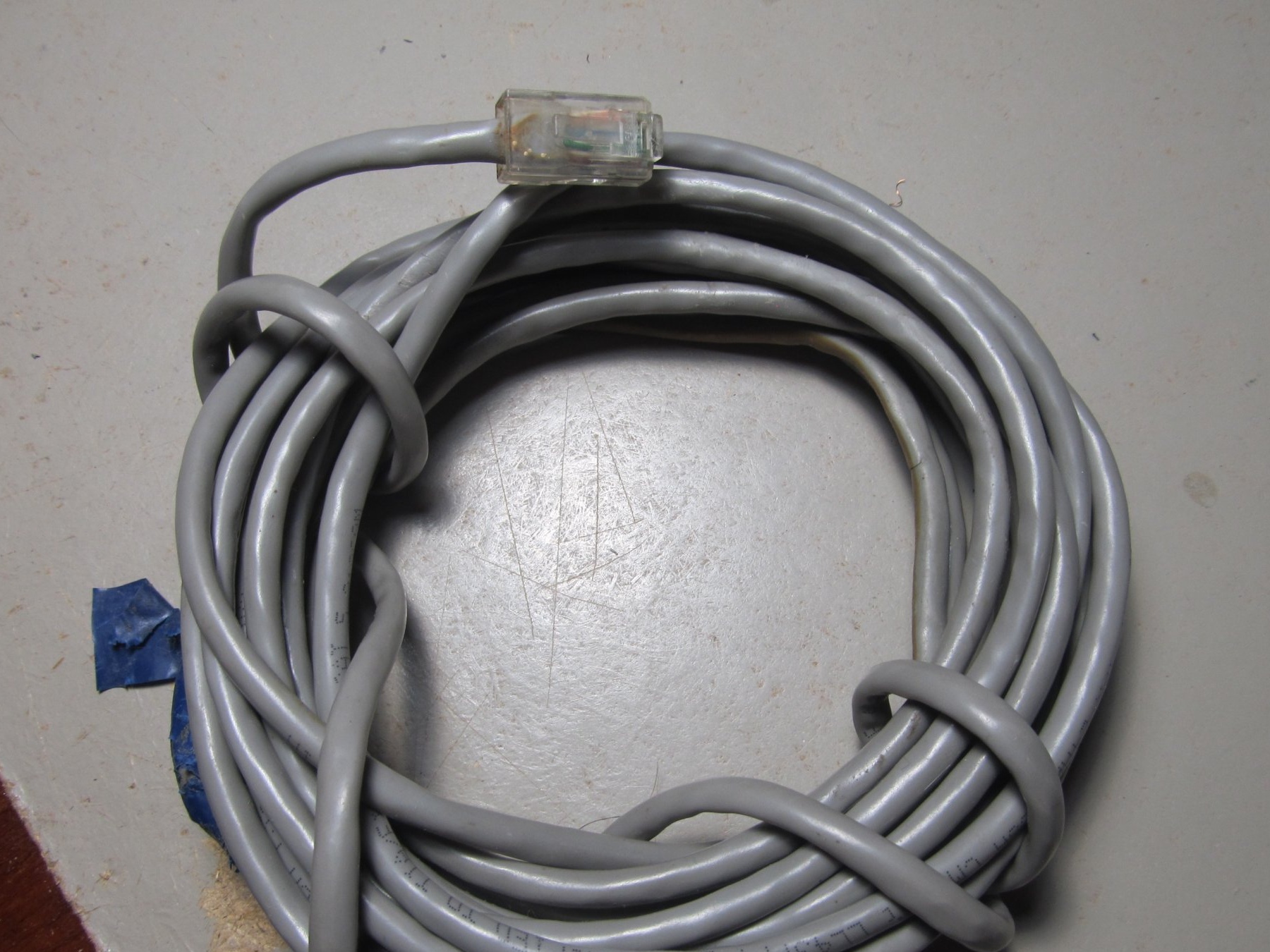
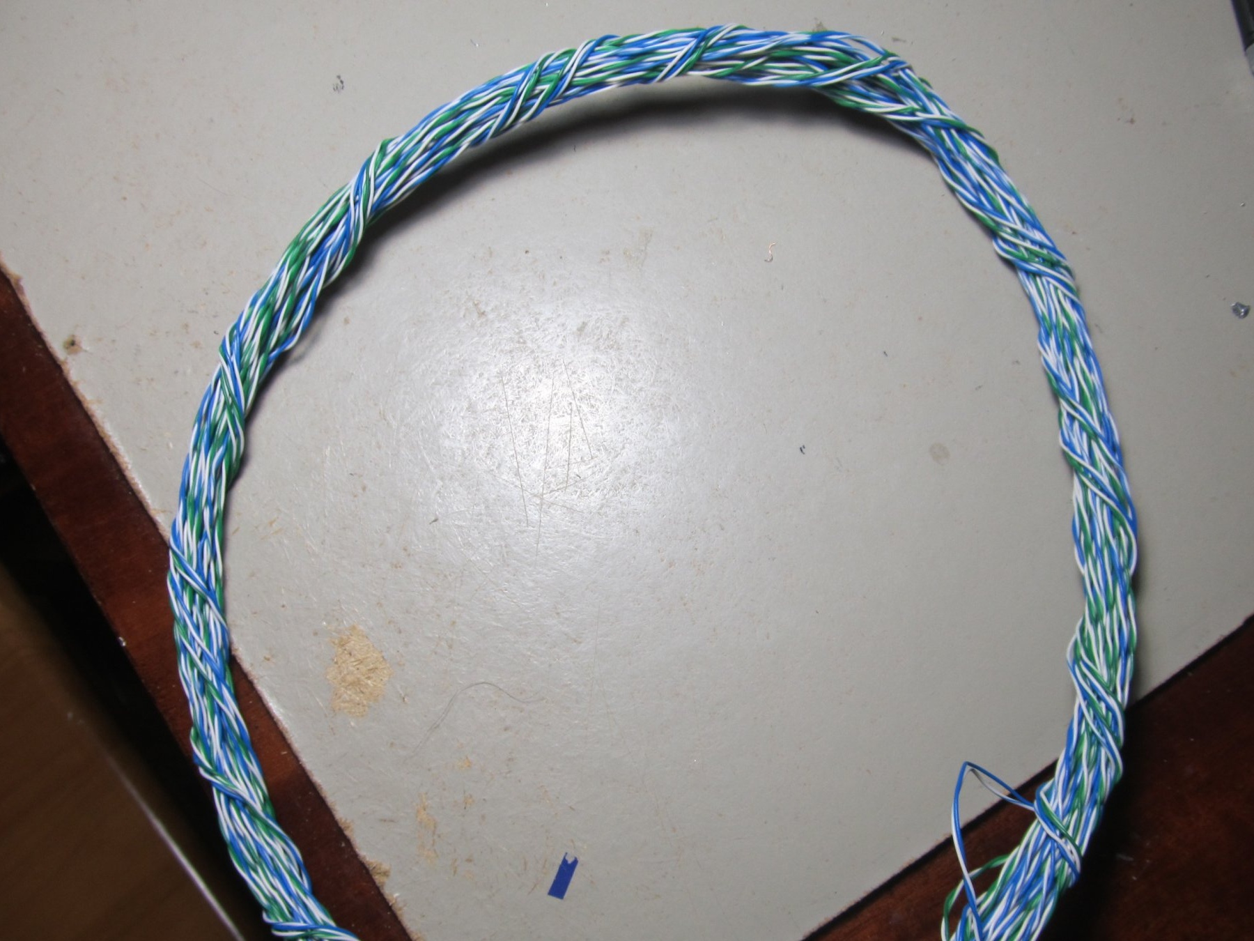
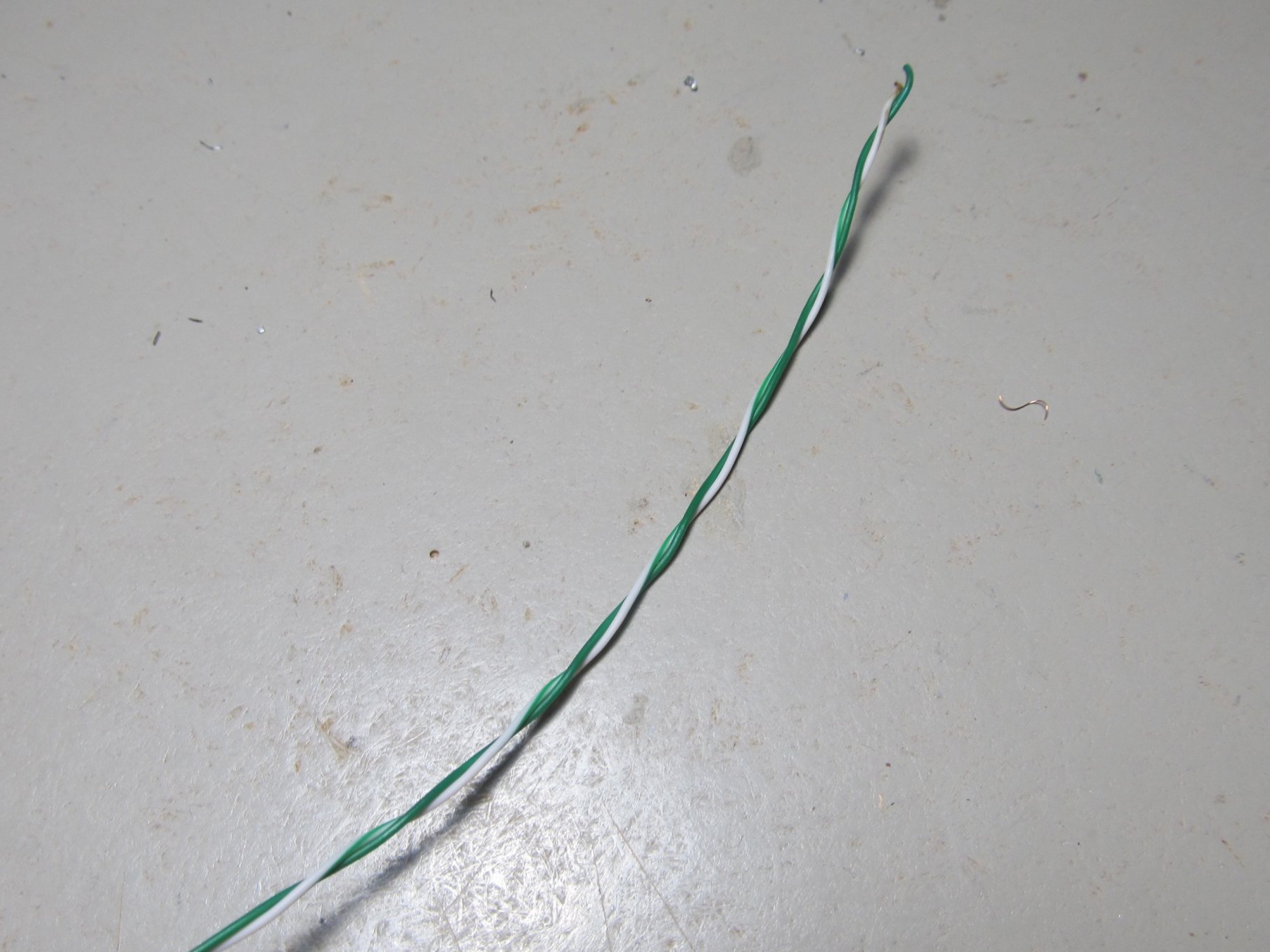
He took off the shell. There were enough wires. Two wires were enough for me, and they also shook the coil.
According to the scheme, the coil is 19 cm in diameter and contains 25 turns. I’ll immediately notice that you need to make a coil of this diameter based on what you are looking for. The larger the coil, the deeper the search, but the large coil is hard to see small details. A small coil sees fine details well, but the depth is not great. I immediately wound myself three coils 23cm (25 turns), 15cm (17 turns) and 10cm (13-15 turns). If you need to dig up scrap metal, then put a big one, if you look for small things on the beach, then the coil is smaller, well, you’ll figure it out yourself.
We wind the coil on anything of a suitable diameter and wrap it tightly with electrical tape so that the turns are tightly next to each other.
The coil should be as flat as possible. The speaker took the first one.
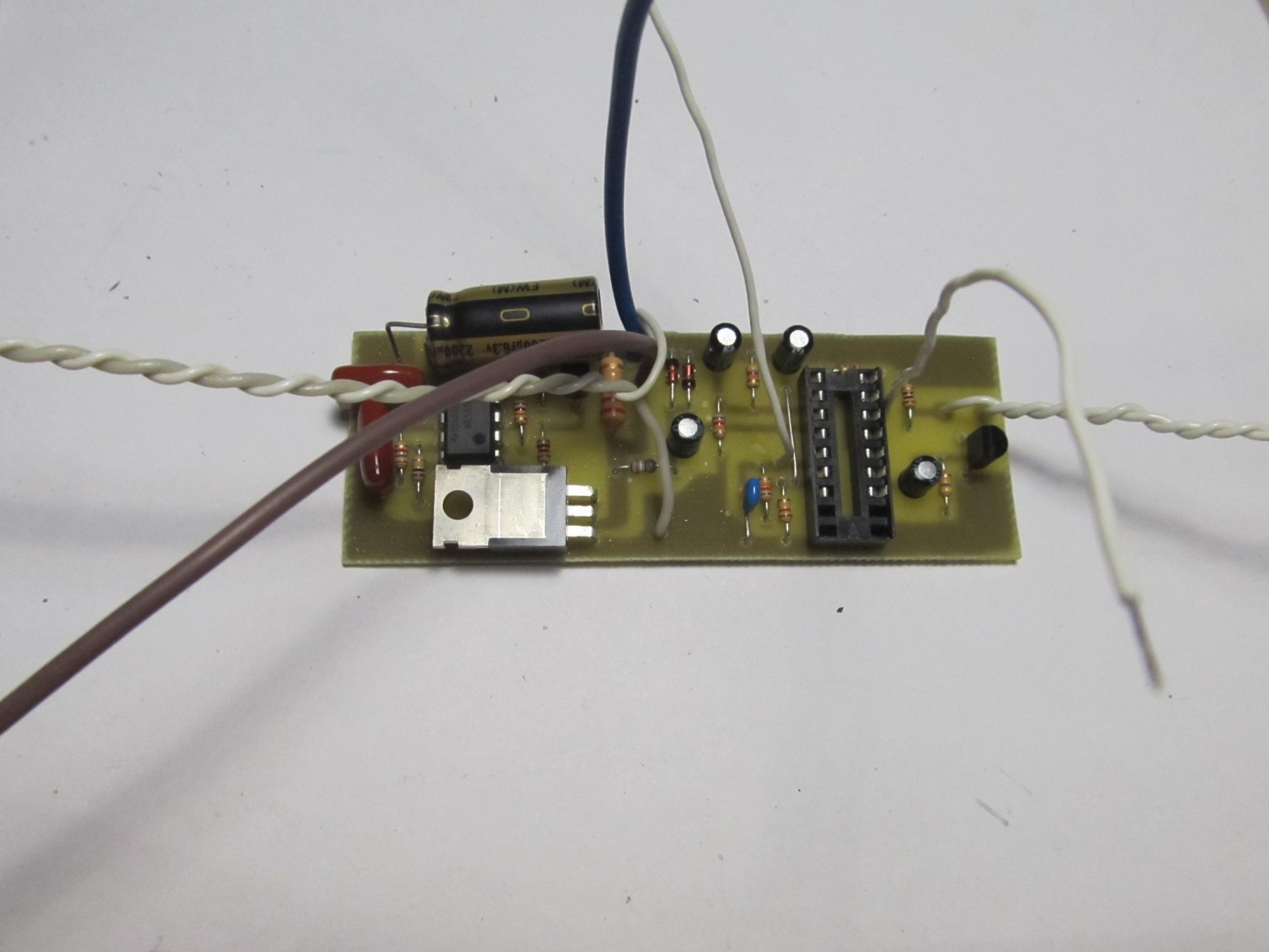
Now we connect everything and try the operation scheme.
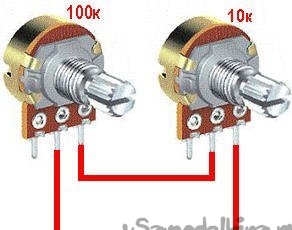
After applying power, you need to wait 15-20 seconds until the circuit warms up. We put the coil away from any metal, it is best to hang in the air. After we start to turn the 100K variable resistor until clicks appear. As soon as the clicks appeared, turn in the opposite direction, as soon as the clicks disappear enough. After that, we also configure the 10K resistor.
At the expense of the K157UD2 chip. In addition to the one that I picked out, I asked another neighbor and bought two on the radio market. I inserted the purchased chips, turned on the device, and he refused to work. I racked my brains for a long time, until I just put in another chip (the one that I pulled out). And it all worked right away. So that’s why the adapter socket is needed to pick up a live microcircuit and don’t suffer with soldering and soldering.
Purchased Chips
Mine and the one that my neighbor took
Everything is ready, it remains only to make the bar and put the board in the case and in search of treasures)
Here is a VIDEO test
Tests of the house were carried out on an average coil with a diameter of 15 cm. So the golden ring caught 18cm in the air, 30cm scissors. table lamp 50cm. which is not bad enough for such a metal detector.
Download the sketch of the circuit board: