» Electronics »Automatic circuit breaker

Automatic circuit breaker


One late autumn evening, I broke into the country (tired of my wife, probably). He turned on the switch and the light in the living room - a bright flash, and all the lamps (ordinary incandescent) burned out. I went to look for a multimeter. Bah, I have 285 V in my network! And if "0" were burned out at the substation, all 380 V would be mine! What would happen if I didn’t turn off the switch and leave the refrigerator or TV plugged in? In the best case, they would have burned down. And so a fire could occur due to a short circuit. So he sat all evening by candlelight and ate canned food warmed up on Bumblebee (yes, I still have such a device). The problem somehow needs to be solved.

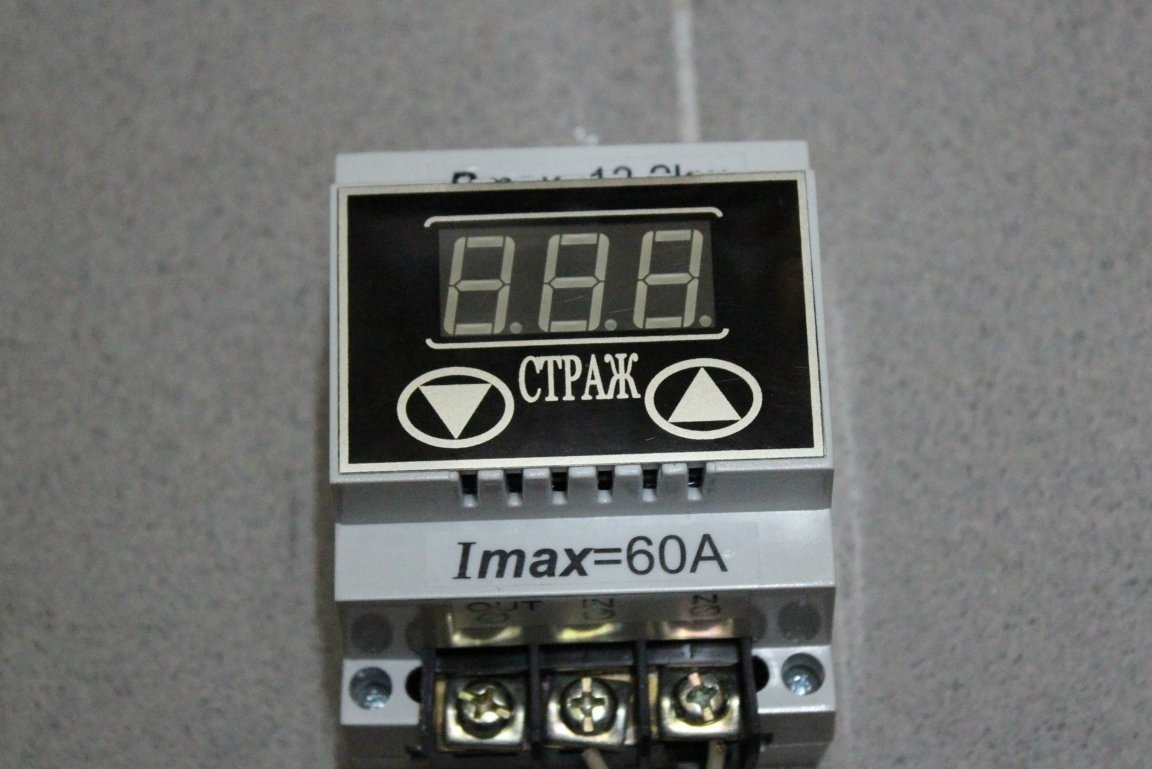
I arrived in the city the next day. I knew that there were devices that cut down the network with increasing voltage. I did not like them at the cost of up to 6,000 rubles. (the price depends on what current they are designed for). In addition, the relay is their executing element - my electronics in the country, while they will turn off the energy.

And if you make yourself such a device based on a high-current triac? I rummaged through the net and found a suitable scheme. I did not like only that the KU208G triac was used as a key. They are very capricious in work, and in terms of power they do not suit me. I decided to replace it with BT 139-800E.127 (it is inexpensive and reliable). At the same time, you need to change the control transistor to ST13003 (which is more suitable for the parameters) and the zener diode to 1N5349BRLG. The resistance power R1 must be increased to 5 W, and the diode VD2 should be changed to 1N5408. Then you can squeeze about 10 kW, which is what I need.

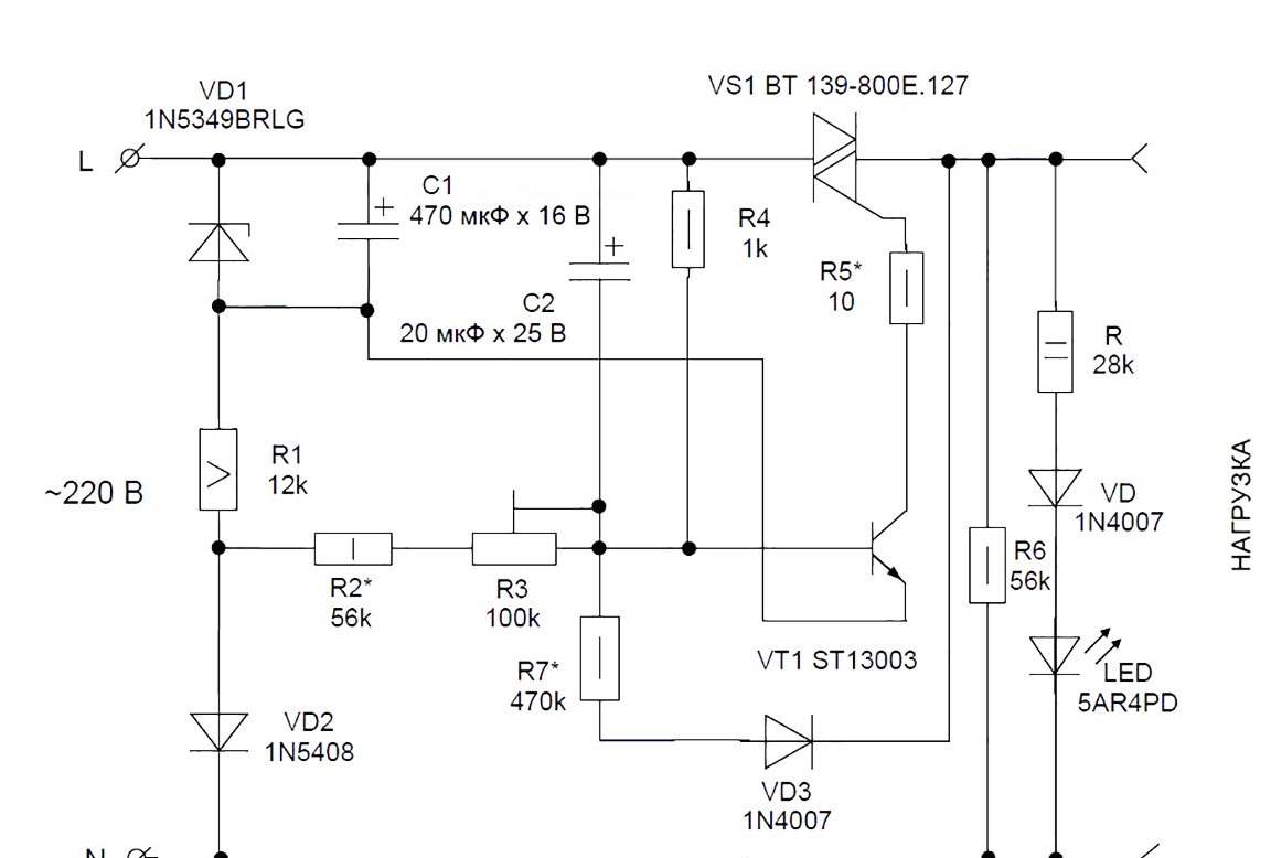
The key element is the triac VS1, the control electrode of which transistor VT1 is supplied with a negative voltage. Resistor R5 is used to limit the current. The reference and control voltages are removed from the parametric stabilizer VD1-R1-C1. In a chain with it is a diode VD2, which supplies the control voltage, which varies depending on the voltage in the network.

When the voltage in the network (and, accordingly, on the resistive divider R3-R4-C2) reduces the emitter current of the transistor to zero, the triac closes. Positive feedback, built on the R7-VD3 chain, provides reliable switching of the transistor. The current through feedback is summed with the current at resistor R3, increasing the voltage at the divider R3-R4-C2. This reliably turns off the transistor and, of course, the triac.

The value of the resistor R3 determines the trip voltage.The value of resistor R7 is the spread between on and off.
To indicate the operating mode at the input and at the output, I decided to put two LED chains. The output chain will also load the triac at idle (then R6 can be excluded).

What is necessary:
1. Soldering iron.
2. A set of electronic components + printed circuit board.
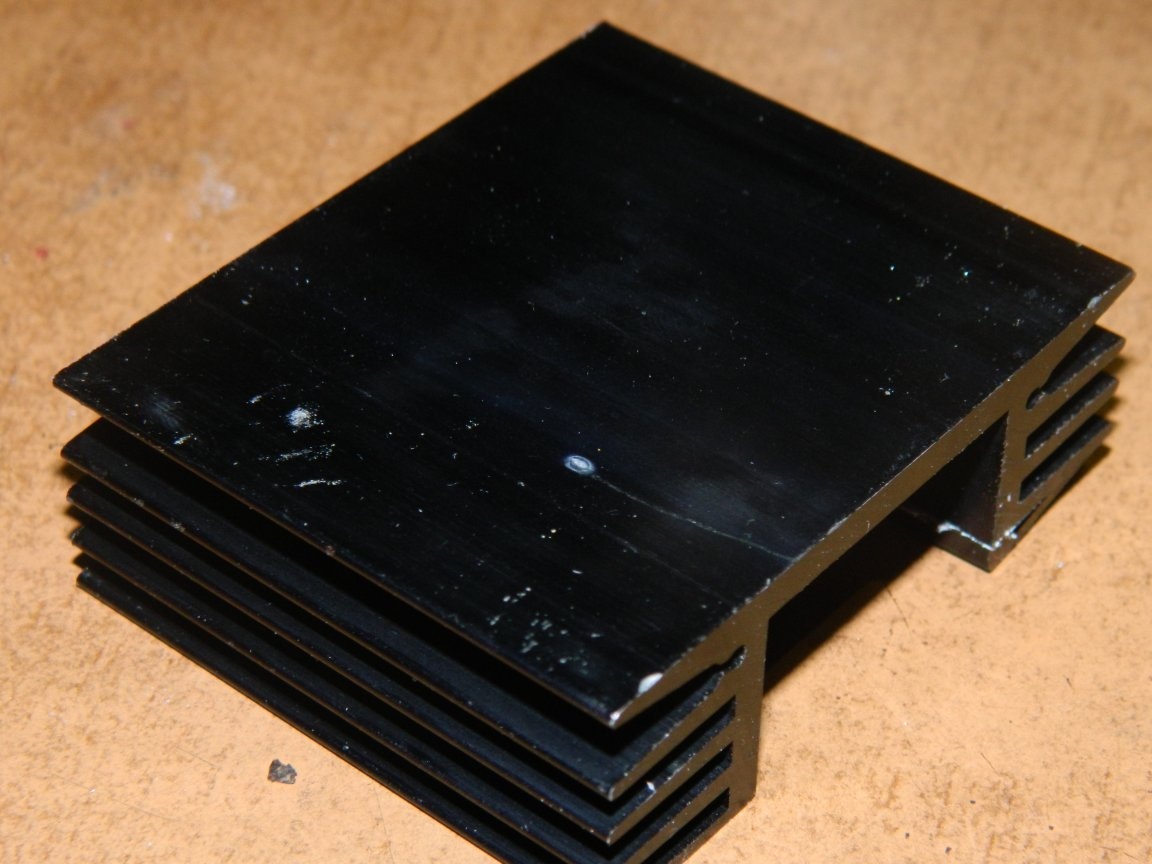
3. The radiator for the triac.
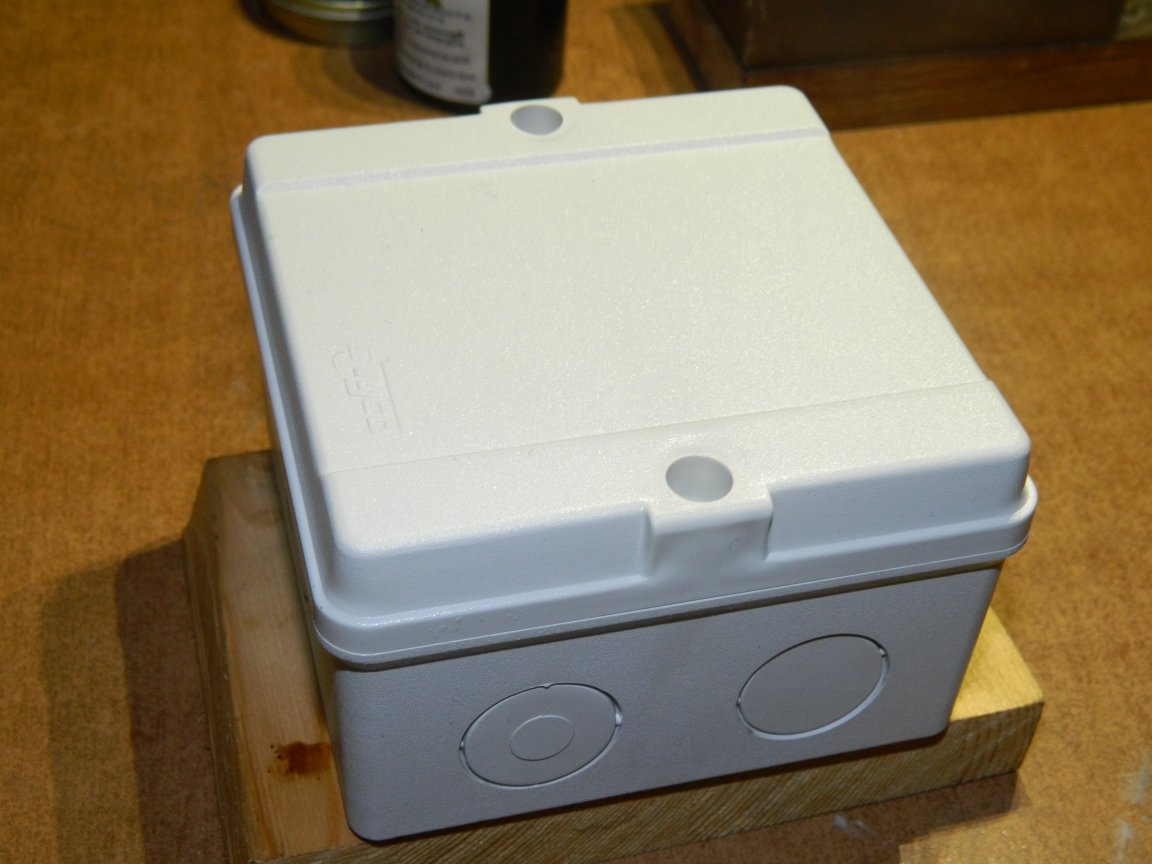
4. Housing for the product.
5. LATR to configure the circuit.
6. Screwdriver, tweezers, scalpel, side cutters.
7. The drill.
8. Multimeter.

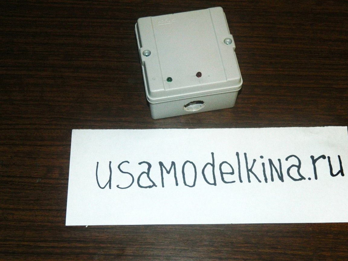
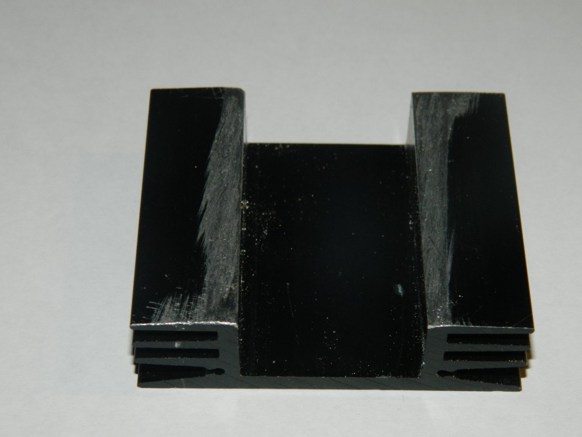
Missing (5-watt resistor R1 and triac VS1) I bought in the store "Chip and Dip" for 50 rubles. The remaining parts were in stock. To cool the triac used heatsink HS 304-50. Its area is more than enough. Yes, I bought it in Castorama for 57 rubles. mounting box for the case of the future device.


I drew a printed circuit board in the program Sprint-Layout 6.0.

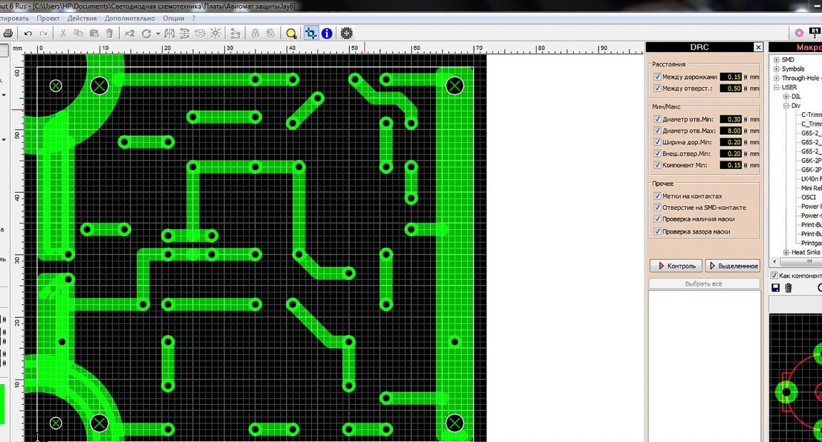
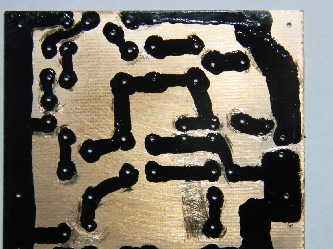
He printed on an inkjet printer on plain paper mirror, then glued to a piece of fiberglass, suitable sizes. Previously fiberglass was treated with fine sandpaper with detergent Seth. With a Ø1.0 mm drill, I drilled holes for parts and technological holes and washed paper off with warm water.

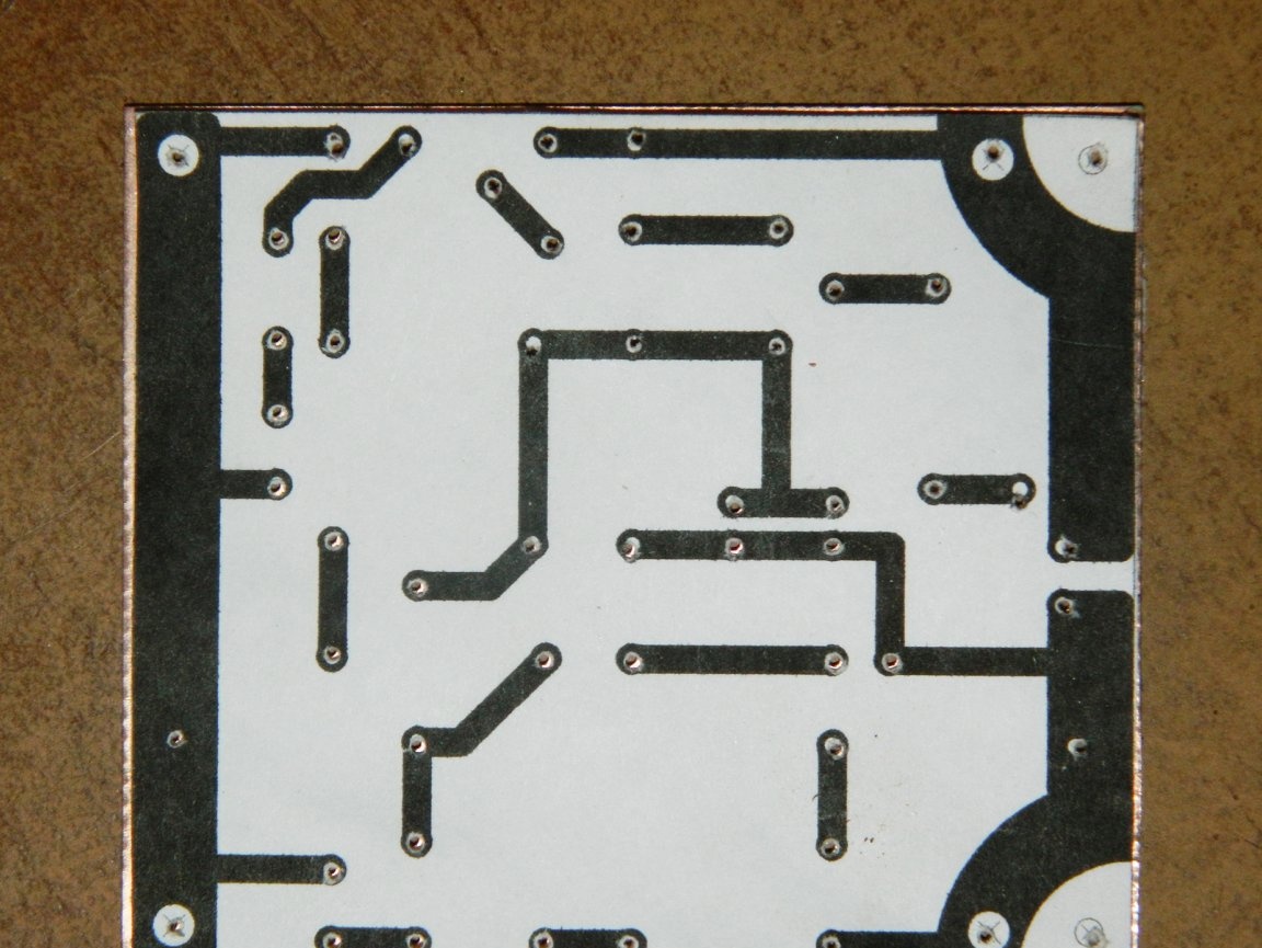
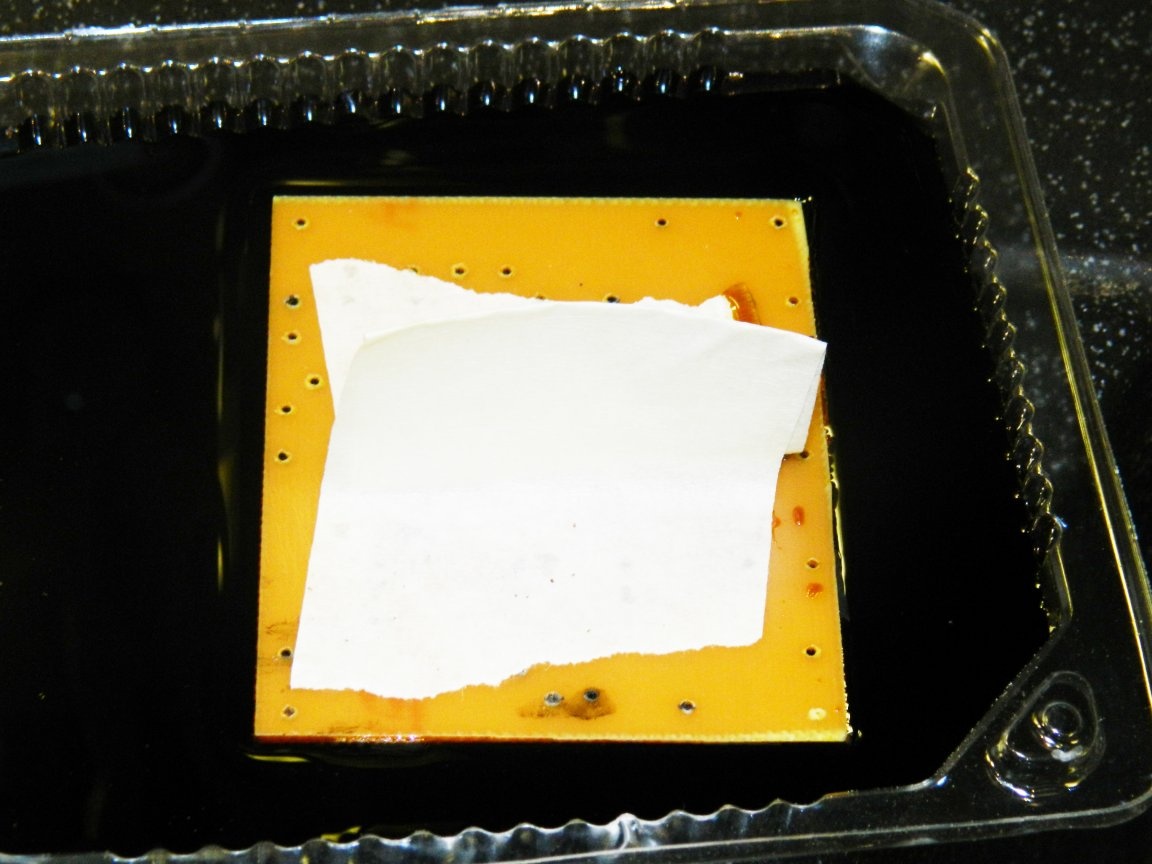
He drew a printed circuit board with a special marker. Then he placed the board in a solution of ferric chloride for half an hour.

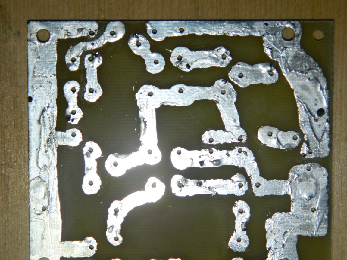
Chlorine iron is difficult to wash off from the hands, so I made a kind of pen from masking tape. Acetone washed off the paint. I drilled the technological holes to the required diameter and soldered the board conductors with a soldering iron. I finished with the board.


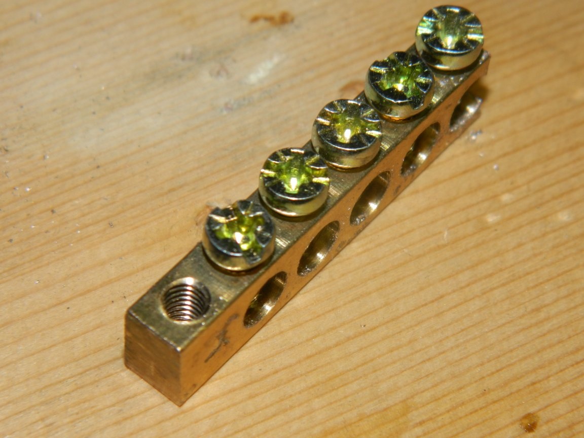
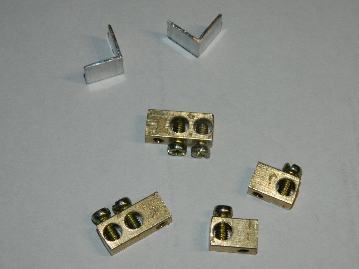
The extreme parts of the grounding bar, where there are perpendicular threaded holes for mounting, came up as contactors. I sawed two corners to fix the board to the radiator. The radiator did not fit literally 2 mm into the case. With a drill I cut from two sides on the shelf. With an area of ​​230 square meters / mm, this is not critical.


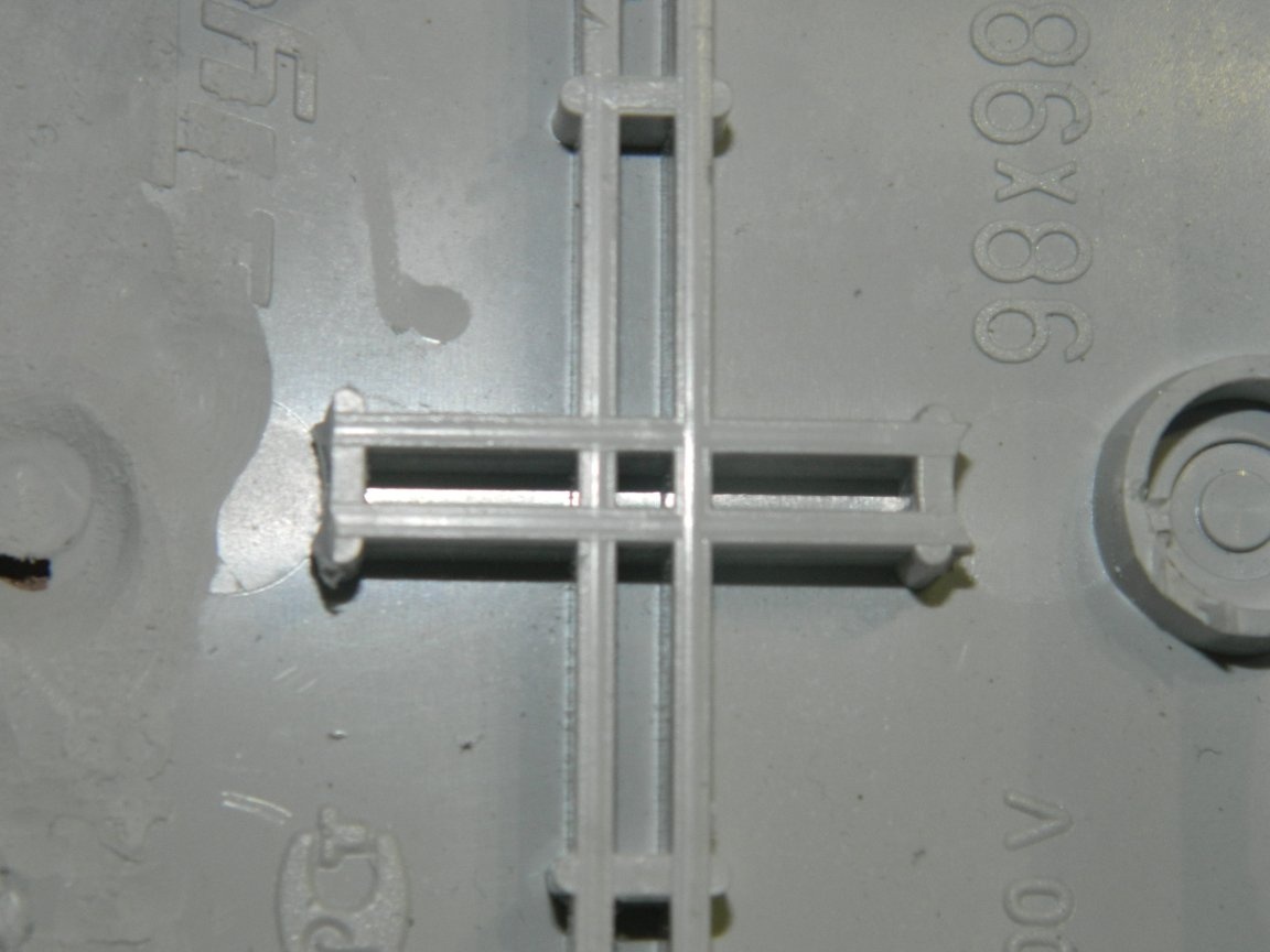
I removed tides from the bottom of the mounting box with a drill that only interfered.

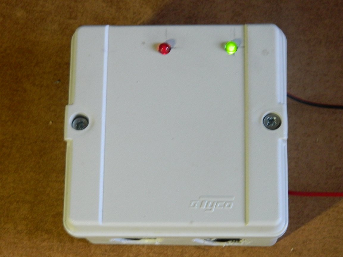
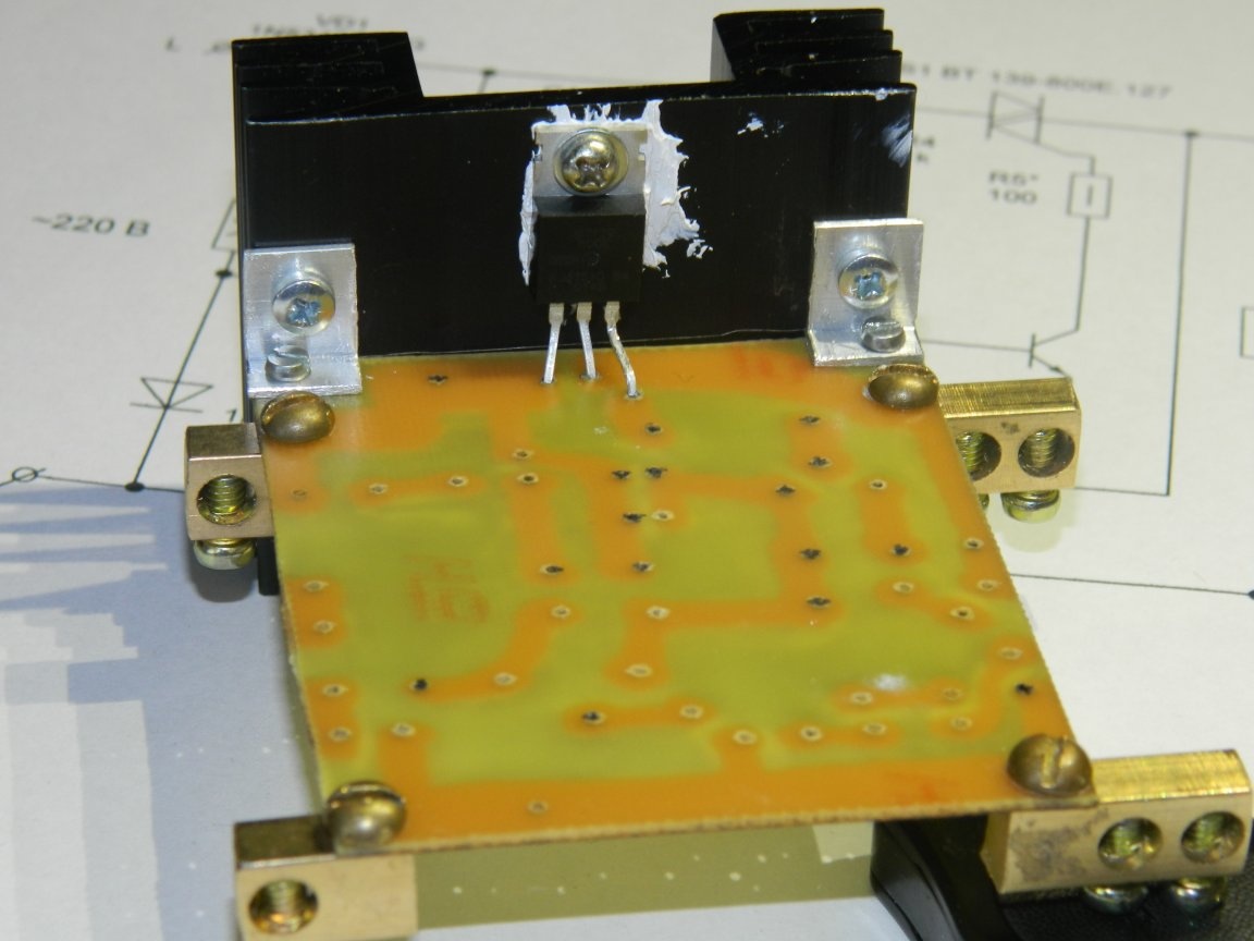
I fixed the board to the radiator at two corners, and I calculated so that the indicator LEDs could exit through the cover. The triac was mounted on a radiator through paste KPT-8. The base 2 of the triac is connected to the cooling pad, so the contact of the radiator with the input / output contactors is fraught with a short circuit, as well as with the conductors on the board.

Then soldered the remaining parts. Instead of a 20 μF × 25 V capacitor (I just didn’t have it), I put two 10 μF × 50 V in parallel. I soldered the indicator chains so that the LEDs slightly exited through the pre-drilled holes in the cover.

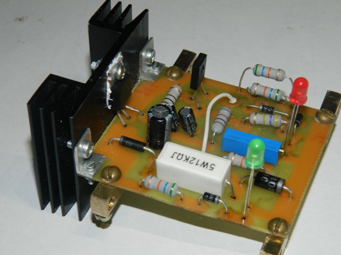
R3 set the average value of the protection threshold. I connected the LATR and the multimeter and made a more fine-tuning. R5 replaced with 10 ohms for the stability of the triac.

I did not have a 28k by 2W R resistor for the output chain with a red LED. I put two in parallel at 56k per 1 watts. The input circuit with a green LED does not affect the operation of the circuit, therefore it is not shown in the circuit.

At a voltage of 180–250 V, both LEDs light up. When the voltage rises to 255 V, the triac disables the phase (only one green LED is lit). The triac again provides a phase to the load when the voltage drops to a level of approximately 235-240 V.


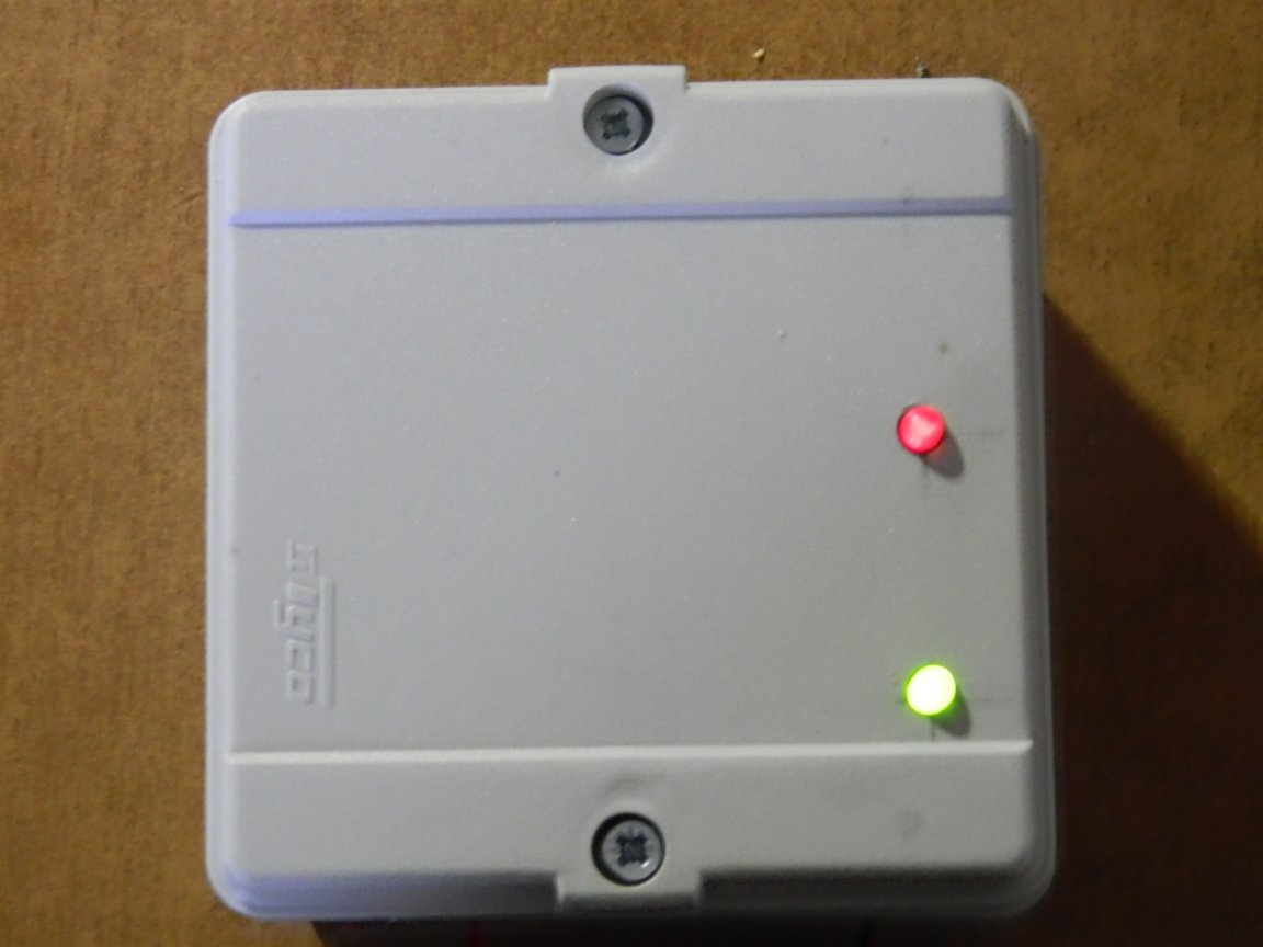
Dimensions of the structure are 60 x 90 x 90 mm. All openings in the mounting box have been specially opened to improve circuit cooling. Spent on the device a little more than 100 rubles, but several days of work. I think it's worth it!
8.6
9
8.2

Add a comment

    • smilesmilesxaxaokdontknowyahoonea
      bossscratchfoolyesyes-yesaggressivesecret
      sorrydancedance2dance3pardonhelpdrinks
      stopfriendsgoodgoodgoodwhistleswoontongue
      smokeclappingcraydeclarederisivedon-t_mentiondownload
      heatirefullaugh1mdameetingmoskingnegative
      not_ipopcornpunishreadscarescaressearch
      tauntthank_youthisto_clueumnikacuteagree
      badbeeeblack_eyeblum3blushboastboredom
      censoredpleasantrysecret2threatenvictoryyusun_bespectacled
      shokrespektlolprevedwelcomekrutoyya_za
      ya_dobryihelperne_huliganne_othodifludbanclose
207 comments
The efficient answer Nruter
Quote: maximace
for me the UZO dark forest

There is nothing wrong with the RCD. A differential current transformer is installed inside, which controls the operation of automatic shutdown.If on your fingers, then the RCD works like this - voltage is applied to the input terminals L and N. From the corresponding output terminals, the voltage goes to the consumer. If you turn on the load (any, a light bulb, a household appliance, etc.), then alternating current will flow through it along the circuit L --- switch --- bulb --- N. The RCD measures the current that has passed through circuit L and returned along circuit N. Ideally, these currents are exactly the same. If somewhere the wiring has a notch, poor insulation, etc., then part of the current will leak. In this case, the current on the circuit L will differ from the current on the circuit N. With a difference of 10 mA, 30 mA or 300 mA, the RCD will disconnect the consumer from the network. That's all. I want to note that the RCD does not perform the functions of a circuit breaker with overcurrent protection and there is no thermal protection in it. For these purposes, a circuit breaker, for example, series BA47-29, is used. Therefore, RCDs are used only in conjunction with AB.
But there is also a device that combines both RCD and AB. It is called a differential circuit breaker.
Chlorine iron is difficult to wash off


For several years I switched to peroxide + lemon + salt. I do not regret it at all. Availability to go to the store, the cost is cheap, the etching rate is not lower than that of HZ. And no rust spots.
In general, the topic of grounding and grounding is the most sensitive topic in electrics. About 80 percent of “professional” electricians cannot really explain how they differ and when they are useful, and when, on the contrary, they are dangerous. Where I studied and worked, almost all from year to year, failed the TB exam on the same issue, moron.
Well then, it turns out that it is not needed at all, since there must be either a spark gap in the shield, this if there is no grounding, or, if there is one, surge arresters, inside which, by the way, large varistors live.
For RCDs, grounding is not necessary at all. The principle of operation of the RCD is to compare the current flowing through the phase conductor with the current flowing through the zero. If they are not equal - shutdown.
Zeroing is used everywhere. The shields now also require a nullified case.
Thank you all for setting out your thoughts on RCDs, a lot of interesting and useful things. But for some reason they did not touch upon the point that grounding is necessary for the operation of an RCD. But it is not everywhere.

As my friend said about 16 fl. the house in which he lives "The house was built by vocational schools under the guidance of a drunken foreman" xaxa Indeed, when he moved into this house, it turned out that the phase of the electric stove is not the earth! And this is no longer funny. They reworked this shit on their own.

In my apartment, an electric stove (housing), as I understand it by indirect measurements, is not grounded, but connected to a neutral wire. In general, a shield for 4 apartments, I saw that several wires are connected to the shield body. And it is not clear whether there is land or zero connected there. So I think you will put an RCD, but will it work correctly? What do you think about this?

P.S. In our house, sockets do not have a third (ground) contact.
The input is three-phase. For each phase, what goes to the outlets and, for example, if the same heating is not through an outlet, but through a switch (not an automatic switch!), First we pass through an RCD (with the corresponding current - one step more than the maximum current on all lines after him), and then through the machines. A bathroom and a bath can be in one phase (for insurance - after a general RCD of this phase).
It turns out 1X300 mA, 3X30 mA and 1X10 mA.
Quote: 2Dem
RCDs are three-phase.

Typically, three-phase devices are three times thicker than single-phase. Is it wrong with an RCD?
Quote: Ivan_Pokhmelev
Introductory fire rated at 300 mA. On sockets total at 30 mA. To the bathroom 10 mA.

But are we talking about each phase? Total, you need to multiply the number of RCD by the number of phases. Get fucked up.
I have in my country house a limit for each phase of 5.5 kW. Terribly uncomfortable. I do not know how everyone shares these powers.3 phases I considered too bold + had to be broken so that the excess was no more than 5.5 kW. I got it with a power per phase not exceeding 5.5 kW (and the power in the group is not more than 16A): A1 children's room + heating, A2 Stove, A3 External output, A4 Adult room + kettle, A5 independent source + microwave, + knife switch, for all but A5. In phase 1 A1 + A4, in phase 2 A2 + A3 + A5. How should I put an RCD? I just think that it will be necessary to do groups for a big house.
PS How is 5.5kWh3 enough for everyone? We have either 1 phase 12kW or 3x5.5. I already think that it is easier to make a 12kW wiring of one phase, the power is less, but it is easier to divide it.
Introductory fire rated at 300 mA. On sockets total at 30 mA. To the bathroom 10 mA.
Namely in the versions ... MD they promise 20 ms, not when the varistor is triggered, but when protected according to the set threshold. For the rest, the Meander guarantees 200 ms.
RCDs are three-phase.
Quote: maximace
Do you personally have any experience with Tomzn?

Really beautiful. I like all their products much more than the trash that we sell as almost elite, especially if it's ABB or Legrand. It’s just that practice has already shown when they invite to a cottage, the owner of which has been “catching an electric drum” for a long time, it is worth throwing out the products of these companies and putting in the same IEK, as the drum goes away. I mentioned IEK because at the moment they make the best machines and no one even catches up close. But I try to install everything else from Tomzn, there were several guards entirely with their products, customers wanted beauty so that only one logo on each button)) They have one important plus, these are 1 / 2DIN machines, by the way, they are “repainted” by Meander . I myself, after many comparisons and testing, settled on the Tomzn voltage relay.
Damn, for me the UZO is a dark forest. I know what it is, but the fact that they still need to be put as much as three pieces. I always thought that at least they should be placed in wet areas, i.e. to the bathroom. There is one RCD in the apartment, probably at 30mA. And now it turns out that three are necessary? And even for each phase? This is 3x3 = 9 only one RCD? At the men in the country in a small house held two phases. Five groups were made into two phases + an introductory machine (instead of a knife switch). And in mind you need 3x2 = 6 more RCDs?
I found the data that interests me. Even a relayed up relay (not everyone, of course) can provide a contact release time of 10 ms. A shabby triac 0.15 ms !!! E !! And the shock current is 350 amperes !!! And the relay cannot.

By night, I’ll definitely collect this device. The soldering iron has already turned on.
And what to say about them, an extremely useful thing, if applied correctly. I like them more than differential automata, because of the greater information content, but the latter also have the right to use. The most important thing is their proper application. I constantly come across, including even in coordinated projects, it comes across that everywhere an RCD is stuck at 300mA, and then the glitches of the electricians are written off to the drum. True, I want to beat such needlewomen))) In fact, everything is simple, just one rule. Introductory RCD - 300mA, set after the introductory machine, but there are nuances. If you plan to constantly use any pumps (for example, drainage) and other similar loads, then for convenience it is worthwhile to provide a separate RCD for 300 mA, connected to the input, by the way, it will signal that the engine is in a dying state if the RCD is cut off, and without RCD everything works - khan krutilke;) In any case, the introductory RCD will perform this task in the same way, but it will disconnect everything. Next, set the second RCD to 100mA. After it, all the wiring is done, except for outlets. Well, and the third stage, an RCD of 30 mA, only sockets and nothing more.
He didn’t claim it, but, only, he warned! help
Yeah, you still need to immediately realize the "inclusion through zero", that is, at zero voltage in the network, between periods.
Mustache, guys, by night I solder the experimental circuit of the surge protection device and increase the network voltage. Trip time 10 ms.This is a theoretical and practical limit. Kanesna, ask, how will I measure this time? I have an idea. The load power is still 2 kW. OK for a start. goodgood
Let the businessmen smoke nervously on the sidelines.

The main details have already found lie in front of me. The problem is where to urgently find LATR. He has a friend, I know for sure, but he doesn’t take the pipe. Apparently, cattle got drunk xaxa
As rightly noted Ivan_Pokhmelev , there is a risk that the varistor, connected in parallel with the load, will burn the triac with its current during a voltage surge.
So put it before devices of the proposed maxi.mus and all things.
That would make a delay for the protection trip 10ms (half the period of the mains voltage). But I seem to know how. This is real.

I’ll raise the datasheets to the reels and triacs and from here I will dance smoke
I guessed about 20 milliseconds tonight !!! But it was time to go to bed. T = 1/50 = 0.02 (20ms) The period of the mains voltage !!! clapping A Valery said i get drunk. preved
That's what I thought, since we started talking about protection and security yesterday, let's discuss RCDs (residual current circuit breakers) along the way. Very important thing. Speak out who dealt with them ...
2Dem, You recently wrote correctly about varistors and, especially about 20 ms, I’ve been thinking about them since last night.
By the way, varistors now began to shove almost everywhere, I won’t say that it’s bad, it just happened right now that the same Meander writes 20 ms on the top for retail, just hinting that with a strong increase in voltage, the varistor will work first, just by it turns out to tsiferka, and only then electronics will do the job.
For retail, all manufacturers write what they like, but it’s worth requesting documents for the project for a tender, as they will already have completely different numbers. And since in this case the responsibility "for words" is much greater, then the manufacturers suddenly become more honest. Therefore, still ~ 100 milliseconds.
Dischargers are needed only on the opening shield in the house. There is nothing for the arrester to do in the apartment panel of an apartment building; non-linear voltage limiters (arrester) are applicable here from an SPD.
And all UZMs have a varistor at the input.
Quote: R555
maximace, but do you have 3 phases in your apartment?

The apartment has 1 phase. At the cottage 3. This year I finished building a guest house. I plan to build a large house (although by today's standards a small one). I stretch the electrician myself. In a big house I plan to install all kinds of protection devices, so all of this is interesting to me.
UZM-50MD, UZM-51MD has an upper limit delay of no more than 20 ms.
Apparently, not an apartment, but a house.
And the varistor with its kiloamperes the triac will not blow out?
maximace, and do you have 3 phases in your apartment?
It’s hard to argue, because not an electrician. Do you personally have any experience with Tomzn?
I advise you to calculate it back. Examples. The very Chinese Tomzn, which besides Ali does not officially get to us, makes awesome voltage relays, in reality to which the same Meander grows and grows.IEK - makes the best automatic machines in the world, if ABB after five trips shortly should be changed, since the contact resistance becomes too large, then IEK products do not have such a jamb. Baltic Resanta - very often really Baltic (and not China), if in a word - shit.
It seems to me that the surge device is a serious device. And he is not eternal. It’s like putting a barrier in the yard, but it breaks, it needs to be serviced. And then I feel sorry for the money. So it is here. Sometimes I read all sorts of articles about similar devices. Is something there? Drying up ?, in short they are not eternal. Put another three phases. Pleasure is not the cheapest, but justified. But China, damn it, as I read the book “Poorly Made in China,” it’s still scary to trust the safety of Chinese goods.
Guest Vladimir
For my house, workshop and garage, an initial 3-phase Resanta was installed in the opening shield. With adjustable minimum and maximum voltage tripping protection. It cost at that time 550 rubles, it seems. I stood for three years and refused. Not because of quality, but because of climatic conditions. I wrote a similar one from China almost half the price. It already costs the same until it is refused. This was ensured by more reliable conditions, protecting the shield in a serious way from atm. precipitation.
And what would the author's scheme look like in 3 phases?
This homemade product has a plus in the form of a price. Only 100r. True, for me this is a useless advantage.
No, a factory device on an electromechanical relay has a delay, as I wrote, about 100 milliseconds. This homemade product will not be much faster, so it will not give any advantages.
Right, two different devices. I wrote that. Both devices must be installed because protect against various threats. The surge arrester saves from a lightning strike, and the voltage relay from subsidence or overvoltage. Which of these devices replaces this homemade product? I realized that the overvoltage device and I realized that the factory device has a very long response time and therefore will not save from a jump. As I understand it, you think that factory devices are ineffective and do not guarantee protection. Right?
Well, if 8 amperes, then of course it will. But still somehow it turns out not in a Christian way))) Relay is more reliable.
What are you, in this case and 30 watts to take away is problematic. In general, from a person who worked with thyristors-triacs (1995, 50 years of Victory, Minsk, Dynamo stadium, mine about 5 thousand lamps) - well, relay switching is better.
Author
I tried this device for a couple of years. No problems arose. Yes, I laid down on the maximum capabilities of the triac. But it is used barely by 40%. Two lines (independent) approach the site: high-current (where I include welding and other crap) - the sockets are located outside the house and low-current, which is in the house (refrigerator, TVs, chandeliers, sconces and all other crap). So, I use the device only in the house. And in the house you can take as much as 5-8 A. Will it go?
I highly do not recommend squeezing 10kW from the triac in the TO-220 package. A brick-sized radiator will not help either.
All salt in the thermal resistance of the crystal-substrate transition, etc.
Not quite right. A device that has a removable unit is a spark gap. They come in different orders of voltages (colors are different) and only work if there is grounding. If necessary, I can tell you exactly how to use them, just write a lot and do not want to do it in vain. So, these very arresters, if very rude, protect against 500 volts, operating almost instantly. The voltage relays operate up to 500 volts and have an order of magnitude longer delay. These are two different devices that must be mandatory and together; individually, they may turn out to be useless.
I repeat that I’m never an electrician, but it seems like other devices are used to protect against lightning. They have a removable unit that should burn, but take the bounce from the jump onto themselves. It turns out that this is a device that replaces 2 different factory devices? But doesn’t it save the refrigerator?
In vain you doubt it. Of course, there are buns in the factory devices in the form of a timer for switching on and other amenities, but the basic principle has not disappeared, they protect well from high voltage and are completely useless against high-voltage surges. You can use the instruction from the same Meander (to which, having betrayed ABB now, such as professionals are masturbating) or any other voltage relay, they all have a trip delay of at least 100 milliseconds, which will not save a lot from a sudden voltage surge, for example, caused lightning strikes wires tens of kilometers from you.
I’ve never been an electrician, but I read about factory devices. They certainly do not cost 100r, But factory devices have a threshold setting, i.e. You can set the minimum and maximum voltage in the network and they have a timer, which, for example, is important for many refrigerators. my refrigerator burned out precisely because of the fact that the compressor cannot be immediately turned on after shutdown (as the person who changed me the compressor said). And are factory devices really useless because of their long operation? I honestly doubt it.
in the evening I fell to the cottage (tired of wife, probably)
good
I arrived in the city the next day
Do you miss your wife? smile

We advise you to read:

Hand it for the smartphone ...