Content:
Home page
1. Drawing board.
2. Inertial Drawing Tire.
3. Stencils for dashed lines.
4. Fixture for building tangents and normals to curved lines.
5. How to divide a line and a circle into equal and unequal parts.
How to divide a line and a circle into equal and unequal parts.
How to divide a line and a circle into equal and unequal parts. As a rule, dividing line segments into equal parts is performed in the traditional way: measure the length of the segment, divide this length by the number of parts, and lay the computed size on the line the appropriate number of times. Tell me, was it often possible to break up a segment into pieces this way the first time?
Dividing the circle into equal parts (for example, in the manufacture of flanges, housings with covers, etc.) is also a rather laborious task, especially if you have to divide the circle, for example, by 7; 8; 9; 10; eleven; thirteen; 14; 15 pieces. (For such division of the circle no graphic methods have been developed.)
So I suggest that craftsmen make several simple instruments for quickly, accurately and efficiently solving problems of dividing lines and circles into equal parts.
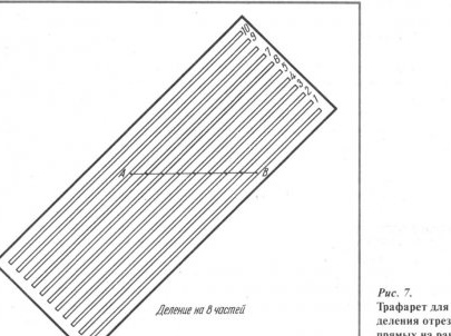
One of them is a stencil for dividing lines from transparent plexiglass (Fig. 7). The stencil has parallel through grooves (slots) located at the same distance from each other. The distance between the slots is usually within 3 ... 50 mm, the number of slots is from 3 to 20 ... 50 (for a stencil size of 120x250 mm). The width of the slots is 0.5 ... 2 mm.
Click to enlarge.
When working with a stencil, it is placed on a divisible segment AB so that one end of the segment AB (for example, point A) is aligned with the first slot of the stencil (and in any place). The other end of the segment AB (point B) is combined with the nth slot (n is the number of segments by which you want to divide the line). Such a combination can be achieved in just a few seconds.
Next, with any writing element (pencil, pen) through the slots located between the zero and pth slots, on the segment AB we put risk marks that divide the segment into n equal parts.The theoretical justification for the fact that the proposed method provides for dividing any segment into n equal parts is the well-known theorem: “If on one side of the corner we put some segments and draw parallel lines through the points obtained, they divide the opposite side of the corner into segments proportional to (or equal) deferred. "
But more complicated device to solve the same problem, which, incidentally, allows you to divide the line not only into equal parts, but also into parts that are not the same in length.
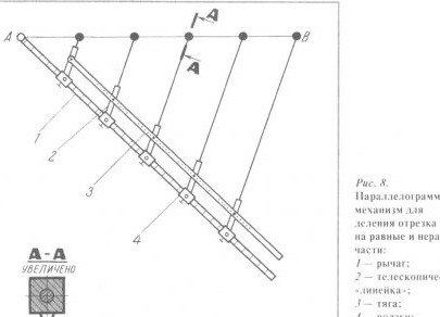
The device (Fig. 8) consists of a parallelogram mechanism, which includes a lever, traction connected to the hinges, as well as one or another number of “rulers”. The lever is equipped with sliders that are able to move along the lever and lock in any position with special screws. On these sliders, with the help of the axes, telescopic “rulers” are attached, which, in turn, are connected by means of hinges to the traction. The length of the telescopic “rulers” can be changed at your discretion. A measuring scale is provided on the lever. At the ends of the telescopic “rulers” needles are mounted. The attachment points of the “rulers” on the traction depend on the position of the sliders on the lever. This is understandable, because otherwise the parallelogram mechanism will not work.
Click to enlarge.
Suppose you want to divide the segment AB into five equal parts. Having such a task, the device is adjusted accordingly, that is, the sliders are strengthened at a distance from each other equal to the distance from point A to the first slide. We repeat, for the installation of the sliders is a measuring scale made on the lever. By the way, the distance of the first slider from the beginning of the lever (point A) is chosen at your discretion. Of course, the “rulers” on traction are also tuned to the same length.
Next, set the end of the lever at the beginning of the segment AB (point A). Then, acting by a parallelogram mechanism, as well as removing or pushing out (if required) the fifth telescopic “ruler”, combine its needle with the other end of the segment (point B). It is clear that the rest of the "line" will occupy a position parallel to the fifth line. After that, adjusting the length of the remaining “rulers” involved in the division, set their needles on the segment AB. All! Drawn on the segment AB points will divide the segment into the required five equal parts.
As already mentioned, with the help of this device it is possible to divide the segment into “unequal” parts by putting the sliders on the lever in the corresponding positions (so that the lengths of the segments are in the right ratio).
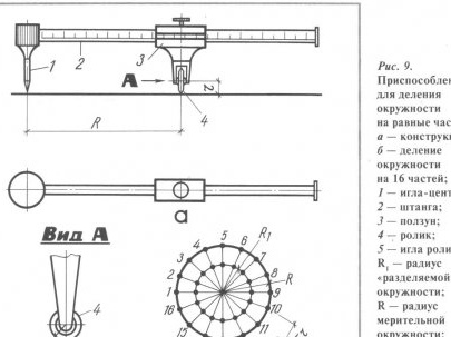
To divide the circles into one or another number of segments, a highly effective device based on a conventional caliper is suitable (Fig. 9, a).
Click to enlarge.
At one end of the caliper rod (in place of the fixed jaw), a head with a mounted needle is mounted. A measuring disk is mounted on the axle on the slider, on the rim of which there is a needle that acts as a writing element. (The disk can rotate in a plane perpendicular to the axis of the bar.) A scale is provided on the bar, and the scale is graduated, so that the numbers printed on it indicate the number of parts into which you want to divide the circle.
We will deal with such a calibration in more detail. Suppose you want to divide a circle of radius R into 16 equal parts (Fig. 9.6). To do this, the slider pointer is mounted on the bar to the mark "16" and the slider is fixed with a screw. Next, put the vernier caliper needle in the center of the circle, press the disk against the paper and draw a full circle with compasses with a radius that is likely to not be equal to the radius Rr. When running in, the small needle that the disk is equipped with will leave 16 marks on the paper. Now, by connecting the marks with the center of the circle in straight lines, we get the corresponding risks on a divisible circle with a radius, that is, we divide the circle into 16 parts.
How did it all work out? We give some calculations. Let r be the radius of the disk; R, is the radius of the divisible circle; R is the radius of the measuring circle, equal to the distance from the slider to the needle (disk) of the compass; n is the number of parts into which the measuring circle is divided. Thus, the length of the measuring circumference should be equal to the circumference of the disk, multiplied by the number of divisions:
2pirn = 2piR or rn = R.
Therefore, in order to divide the measuring circle into n parts, it is necessary to set the slider at a distance R from the compass needle, and R will be equal to rn. This dependence is used when graduating the scale. For example, prip = 21 ig = 5 mm, the slider should be installed at a distance of R = 105 mm from the needle. On the scale in this place and put the mark "21".
The device is simple in design, easy to operate, provides high accuracy of construction (up to 0.05 °). Division of any circle into any number of parts is carried out in 0.5 ... 2 minutes. The advantages of the device are especially evident when dividing the circle into a non-standard number of segments: 5; 7; 9; eleven; thirteen; 14; 15 and others
All described drawing devices provide a reduction in the complexity of drawing work, eliminate routine work and help designers, draftsmen, students studying in drawing drawings.
Content:
Home page
1. Drawing board.
2. Inertial Drawing Tire.
3. Stencils for dashed lines.
4. Fixture for building tangents and normals to curved lines.
5. How to divide a line and a circle into equal and unequal parts.
How to divide a line and a circle into equal and unequal parts.


