» Electronics » LEDs »LED responsive to light

Light-responsive LED

Such a circuit with an LED that is responsive to light can be assembled in just 10 minutes and you need to have a minimum of components for radio components, and of course skills in working with a soldering iron))

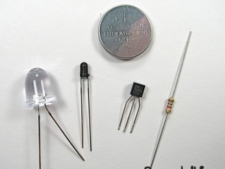
For the scheme you will need:

- one LTR-4206E phototransistor
- one lithium CR2032 battery (3 V)
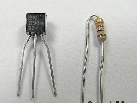
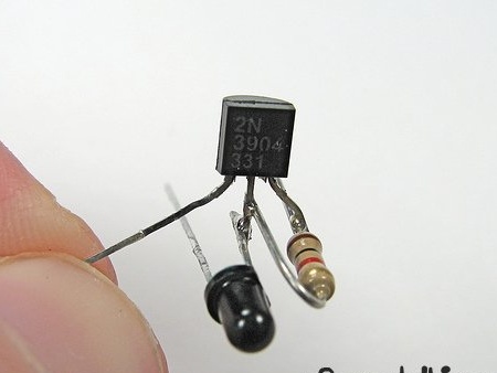
- 2N3904 transistor
- 1k ohm resistor
- soldering iron

So, all the components are assembled, proceed to installation:


Build progress homemade:

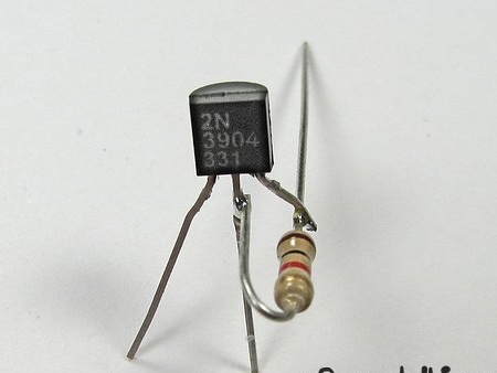
First, take the Transistor and resistor and solder them as shown in the figure:


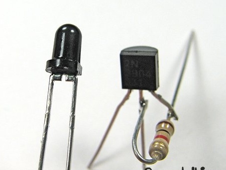
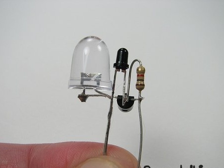
Next, solder a phototransistor to this design:


Next, solder the LED:


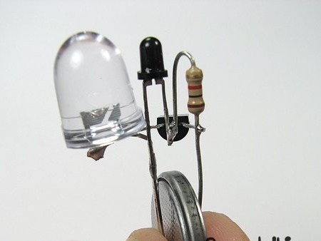
And then the power supply for the LED:


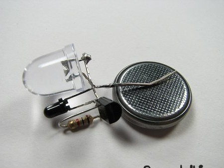
As a result, we have the following:


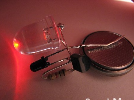
Principle of operation: under light, a current flows in the photodiode, which is supplied to the base of the transistor - the circuit opens. But there is one caveat - you need to think about the placement of the elements so that the light from the LED does not fall on the photodiode, otherwise an uneven, blinking light will be observed.

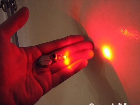
A photodiode can be replaced with a solar battery (panel), and as a source - a battery from a cell. I did all this, and look at what I got:

10
7
6.5

Add a comment

    • smilesmilesxaxaokdontknowyahoonea
      bossscratchfoolyesyes-yesaggressivesecret
      sorrydancedance2dance3pardonhelpdrinks
      stopfriendsgoodgoodgoodwhistleswoontongue
      smokeclappingcraydeclarederisivedon-t_mentiondownload
      heatirefullaugh1mdameetingmoskingnegative
      not_ipopcornpunishreadscarescaressearch
      tauntthank_youthisto_clueumnikacuteagree
      badbeeeblack_eyeblum3blushboastboredom
      censoredpleasantrysecret2threatenvictoryyusun_bespectacled
      shokrespektlolprevedwelcomekrutoyya_za
      ya_dobryihelperne_huliganne_othodifludbanclose
32 commentary
FSK are different, it is possible if, for example, FSK-2, it is necessary to modify the scheme. It should also be remembered that the maximum current through the contacts of this relay is 0.2 A. The load turns on when the FSK is illuminated, if you need to illuminate the stairs in the dark, the signal must be inverted. In addition, depending on the load, an option without a relay is possible, with a power switch.
Plus, a really useful comment. At the expense of power supplies: I have many cheap (~ 40r) low-current switching power supplies from China 220 \ 12V to power the circuitry and relays; drivers for LED strips 220 \ 12V. + This simple little circuit on one transistor or to increase the sensitivity, you can include 2 in the emitter follower, as you showed in the diagram:

How such an option will be working?

Quote: admin
I respect your point of view, but if we ignore all sorts of LEDs, batteries and add a relay, we get the simplest photo relay:
Is it possible to put this scheme into practice, for example, turn on the lighting of the stairs at the entrance to the house?

I ask you to generously excuse me for interfering. The question is not addressed to me, but maybe you still listen to my opinion on this issue. And Ivan (if he answers) will correct or supplement me.

For today, there are pretty good photocells on sale, the cost is budget.
If you have a desire to assemble "your" scheme, then you have chosen it is not entirely successful.
For any you need to "power" the device, which means you need a "power" device. What do you want to illuminate with 220 volt lamps or LEDs? This should also be considered when choosing a power source. It is easier to adapt to already existing lighting (220 volts), which means the relay must withstand the necessary load. The sensitivity of the relay in your circuit is very low, the operation will be unstable (there are many reasons for this).
If there is a staircase in the house, then it can be done as mine. LED strip gives pleasant lighting, the "golden staircase", the wife calls it that. It turns on and off from the photo relay, but it must be placed on the window, where the threshold will be faster. Otherwise, in cloudy weather, in low light, the system will not work.
  
Once again, I dare to offer a not-so-bad option (there are better ones) that will solve your problems. And the shemka is not complicated. You will already have a power source, the operation of the circuit is more reliable and stable.
Good luck searching.
blush Yes, I’ll supplement it. You can easily find radio elements for this circuit in a similar heap ....
 
Look at the diagram above, about this I wrote to you in a comment, and not in its original form, as in the article, but in fact it is the same thing, only with a tuning resistor and relay.
A lot of things you can think of, this circuit + relay = enable / disable something
My mistake is that I did not immediately insert the circuit, apparently we just did not understand each other.
Quote: Ivan_Pokhmelev
Found, by the way,.

: innocent: Another "rip off".
Quote: MNS1961
Ivan, thank you for the professional comment.

What I chewed for you specialists in electronics ... So you are what you demanded, "crumb." And I don’t understand, something else. Sorry, I didn’t understand. blush
Quote: To Delusam
The circuit itself is the most primitive, it is rather a visual aid "photo relay operation". Its practical application is out of the question. If only on toys or trinkets.

But that didn’t suit you ...
Quote: Ivan_Pokhmelev
I don’t mind the claim “it works” - yes, it works, but it’s not home-made, but a layout illustrating one of the many possibilities of optoelectronics, the principle of operation of the photo relay.

Bravo to Ivan !!! With such as Ivan, it is easier to communicate on such topics. He will not look for grammatical errors, but he does not pass by technical mistakes.
: innocent:
I respect your point of view, but if we ignore all sorts of LEDs, batteries and add a relay, we get the simplest photo relay:
Is it possible to put this scheme into practice, for example, turn on the lighting of the stairs at the entrance to the house?
I don’t mind the claim “it works” - yes, it works, but it’s not home-made, but a layout illustrating one of the many possibilities of optoelectronics, the principle of operation of the photo relay. And what toEThais feed parallel-on LEDs from lithium cells without current limiters - I also know, but this does not mean that truly reliable devices can be done this way.
Ivan, thank you for the professional comment.
Found, by the way,.
Quote: admin
"the scheme is primitive, it means it is not reliable and it cannot be applied in practice."
So it is: the favorite entertainment of the “radio killers” is the lack of current limitation through the LED, because the collector current will not limit 1 kilo-ohm in the transistor base with beta = 300, and the light, judging by the case, is 20 milliamperes.
And so as not to ask twice, I’ll add: in addition to the electrical circuit diagram (for myself, I restored it, but this is wrong!) It is necessary to bring the type of LED. And one more thing: why was the infrared phototransistor chosen that does not respond to radiation in the visible range of light waves?
Quote: admin
Well, I won’t ask you any more questions. Your position is clear to me: "the scheme is primitive, it means it is not reliable and it cannot be applied in practice."


The scheme is primitive, but for practical use there are already developed and tested schemes. Why fence the garden?
Well, you can have such a working scheme and 220 volts.

Or such ..
 
There is essentially no discussion here. Can you dot the i, why this scheme can not be applied in practice? For example, to turn on lighting in the dark.
I see the word sarcasm you do not know ... Once again I ask that in this simple little scheme you personally did not like? Why can’t it be put into practice?

I am waiting for a reasoned answer, and not an answer, to study the science of electronics.
It is not clear what is being discussed here. Where is the circuit then? "Masterpiece"? : mask:
Quote: admin
She ... It won’t work, you evade the answer. As they say "brevity is the sister of talent," can you explain in "2" words where in this scheme is a weak spot? Maybe in simplicity lies that reliability? Pliz, explain to the ignorant ...

I NEVER evade the answer !!! There is no brevity in electronics, or rather, it is for those who are knowledgeable.
The weak point in this scheme is not simplicity (you are again difficult for you), but primitiveness. Using this simple circuit, you can explain and demonstrate the operation of the photo relay. For practical application of the circuit is more complicated, you need reliability, clarity of work, adjustment, etc.
Yes, and instruments for tuning. Something like that ...
And such ... Like mine for example.
And also the literature that you must be able to read, and not climb on the Internet and read with such incorrect comments. You need to know how the ESSENCE was said here !!!

Will you be happy with my answer?
Quote: admin
I am not the author of this circuit / home-made, of course this is just a mock-up and using batteries / small-capacity batteries does not make sense for serious projects.

Thank you for agreeing with my opinion. I did not think that you are the author of this scheme, because the author is most likely one of the one and a half billion Chinese, and his name is definitely not Nikolai, although I would like to see or hear the Author.
I am not the author of this circuit / home-made, of course this is just a mock-up and using batteries / small-capacity batteries does not make sense for serious projects.

I shot the video and there just showed the operation of the circuit, and the master himself will decide which source to use, which relay, what load, which sensor, etc.
Quote: admin
A lot of things you can think of, this circuit + relay = enable / disable something

Dear Author, it is impossible to use a relay in this circuit, or rather, it is possible to solder it and make something commute, but with this battery the circuit will work for no more than 2 hours (the relay winding will be a "fool" to plant the battery). About night recharging the battery I will say the following:
A solar battery of this size will charge your battery with microcurrents, God forbid, by 3-5% per night, and it will be discharged by 60-80% per day of operation (remember the quenching resistor installed in series with the LED - you “shorten” your battery with it )
Yes and there is nothing new in this scheme. All Chinese garden "sticks" are assembled in the same way.They work only until the Li-ion battery dies, and this imaginary "recharging" from the solar battery "extends the life" of the battery by ..., yes, it doesn’t extend it.
This is not just my opinion, I tried to turn off the “recharging” of these plug-ins and compare the service life with on and off, the result is the same. Here's how to turn on / off using a phototransistor, this circuit can be used, of course, by applying power not from the battery.
Specifically? Please: night illumination of paths in the garden; turning on / off the circulation pump \ fan in the gel installation; inclusion of illumination of a car at night. And a lot of other situations, inclusion \ off. which depends on the presence / absence of light.

Now you understand what you can apply for?
Quote: admin
A lot to come up with, this circuit + relay = enable / disable something

Well, these are common words, nothing about. Plus and minus. Relays without this circuit are widely used. Everyone was attracted to simplicity (we love it) no need to strain. And whether there will be a specific application, this is no longer important.
Quote: VISARIUS
By this principle, you can make emergency lighting, a nightlight.

How?
A lot of things you can think of, this circuit + relay = enable / disable something
Quote: admin
Think right VISARIUSbut in general, on the basis of this simple scheme you can stir up a lot, the main thing is fantasy!

Any thoughts more specifically?
But I looked ... I liked the idea ... Well, I think there will be where to use solar panels from the saddle "stick" - a couple of pieces are lying in the barn, I once bought in Poland for a penny, but now they are not written anywhere ... So, I think I pick out the panels from them and collect something from such a circuit .....
..... And then the whole depth of my insanity reached me !!!! .....)))))))
.... Mmmm ... Yes-ah !!! .... I'm getting old .... Somehow, this Jewish Alzheimer got to me .....))))) )
It is simple to exclude the dependence of the photodiode on the c / diode. It is only necessary to place between them a lightproof partition or a tubular cap on the f / diode. I liked the idea. And the solution too.
Bliiin, that’s not bad ...: wassat: It just doesn’t work “exactly”: belay:
You can do home-made hands without hands, here the main thing is that the head should work "smoothly": winked:
admin,
Fantasy, desire, raw materials and hands, preferably not very crooked lol
Think right VISARIUSbut in general, on the basis of this simple scheme you can stir up a lot, the main thing is fantasy!
By this principle, you can make emergency lighting, a nightlight. Just have a good stuff Glowing bonsai

You can also do auto-turn on headlights or lights in the corridor.
Aleksej
Cool circuit. Often in my life I worked with LEDs.

We advise you to read:

Hand it for the smartphone ...