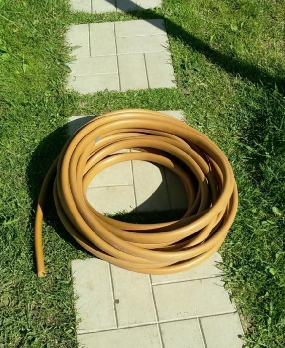
Spring and the beginning of this summer were distinguished in our area by beautiful weather. Dry and hot days delighted holidaymakers, and from the "rest" lovers in the summer cottage they demanded frequent watering, planted do it yourself plants. Watering the beds and filling various containers for heating water require constant communication with the irrigation hose. Then unwind the 20 meter hose, then rewind it. And he constantly twists and breaks, and even not always clean.
As you know, laziness is often the engine of progress. This prompted, in his spare time, to make a device for quick and easy winding (and unwinding) of a roll of watering hose, as well as its compact storage. In the event that a similar problem arises in your household, I propose to consider the above version of the manufacture of a simple and durable hose winder. The garden season is passing, but - prepare the sled in the summer, and the auxiliary device - as time is available.
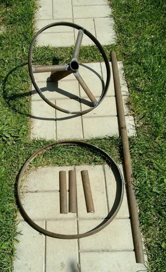
Materials
Material for homemade metal rolling can serve (a circle with a diameter of 6 ... 8 mm, a square, a strip, a thin-walled pipe).
A billet for the manufacture of the presented device was a steel strip 2 ... 3 mm thick and 24 mm wide, formed for stiffness in the form of a crescent.
As an auxiliary material, a plastic water pipe was used.
We calculate the dimensions of the drum for winding the hose.
They depend on the outer diameter of the hose, its length, stiffness, winding density and the preferred proportions of the winding drum (diameter to width ratio). In principle, the drum has the form of a coil - a cylinder, at the edges bounded by lateral planes of a larger diameter.
Depending on the length of the hose used, we determine for ourselves the dimensions of the drum.
1. Assign a preliminary value of the outer and inner diameter of the drum (for example, the outer diameter D = 400mm, the inner diameter d = 200mm).
2. Roughly calculate the number of formed hose coils on the drum, with the selected dimensions. To do this, divide the length of the hose by the average length of one turn C1. C1 = (d1 * 3.14), where d1 is the average diameter of the working part of the drum. d1 = (D + d) / 2 (e.g., (400 + 200) / 2 = 300 mm).
With a hose length of 20m, the number of turns of the hose on the drum will be 21 (20,000 / (300 * 3.14) = 21).
3. It remains to determine the width of the drum.Measure the diameter of the hose (e.g. 25mm). We calculate the number of turns of the hose wound in one row in the plane of the radius of the drum. For this, we determine the value of the working section of the drum b1 = (D - d) / 2, b1 = (400 - 200) / 2 = 100mm.
Then the number of turns of the hose in one radial row is 100mm / 25mm = 4 turns. Therefore, all turns of the hose (21) will be placed on the drum in 6 incomplete rows
(21/4 = 5.25). The remaining free space will facilitate the winding and laying of the hose.
As a result, the width of the inside of the drum will be 6 * 25mm = 150mm.
If necessary, changing the initial dimensions of the diameters of the drum, according to the above method, we find the optimal proportions of the device.
Manufacture
1. Let's make a rim of a drum.
Cut two pieces of the desired length. The length is calculated according to the well-known formula: C = 3.14 * D. In the formula: C is the circumference (blank); D is the outer diameter of the drum (rim).
If bending machine or device in the economy are absent, we will use the means at hand. In small sections, sequentially, using a bench vise, manually bend the workpiece (strip) into the rim of the drum.
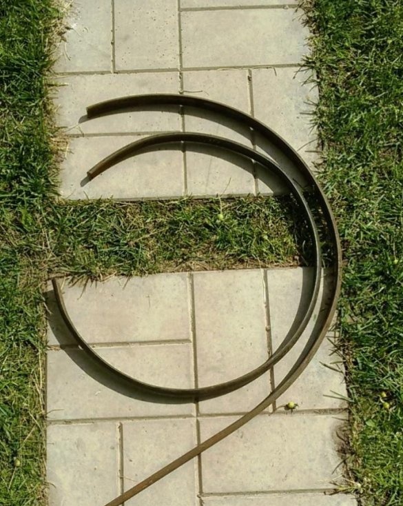
To control the flatness and the maximum approximation of the workpiece to a circle, as a template, we use the wheel of a car wheel. The gap between the disk and the workpiece installed in its flanging (rim), clearly shows the location of the necessary adjustment of the rim geometry. By editing the workpiece, we bring the rim to the required size.
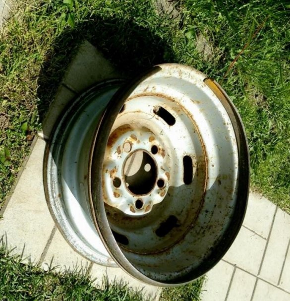
The use of the wheel of a car wheel, significantly helped in the manufacture of the device. The rim of the disk was used as a template, the window of the disk helped with bending and dressing of the rim blank, the disk as a whole served as a welding conductor when assembling the drum.
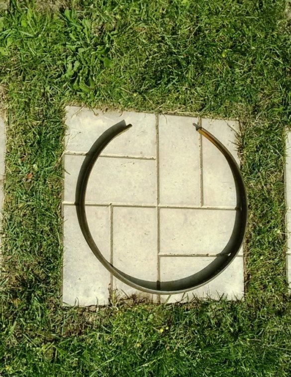
The diameter of the rim determined by the car disc is 360 mm. Since this size is slightly different from the calculated diameter (the length of the workpiece was cut into the calculated size, and the disk appeared during the manufacture of the rim), the blank of the rim in the photo has an incomplete contour. Therefore, in the future, the manufactured rim had to be equipped with an additional element of the same radius.
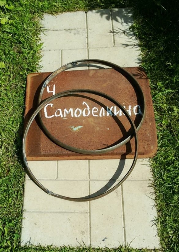
2. Welding the rim of the drum.
We install and fasten in the rim of the automobile disk, the blank of the drum rim, and then the complementary element, after fitting it along the length. We carry out preliminary tacking of parts by arc welding. We remove the workpiece from the disk, correct if necessary and perform the final welding.
Repeat the operation on the second rim.
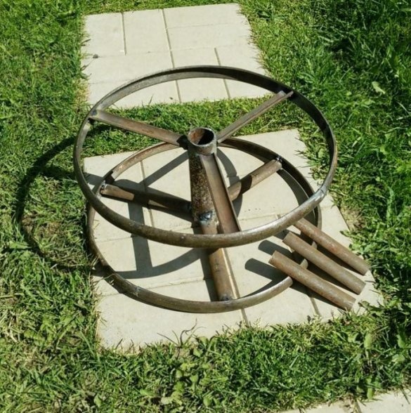
3. Assembly of the winding drum
As the axis for the winding drum, we use a piece of steel thin-walled pipe 35 x 1 (1.5) mm. The axis length must exceed the width of the drum by 20 ... 30 mm. The difference between the inner diameter of the rim and the outer diameter of the axis tube determines the length of three identical spokes for the drum. Cut them from the existing workpiece.
Using the disk as a welding conductor, we set the rim in the flange on the front side of the disk. We center the billet of the axis and fix the gaskets in the central hole of the disk. We evenly distribute the spokes of the drum around the circumference and lay them on the disk between the rim and the axis. River sand located under the disk will greatly simplify the installation and alignment of the axis in height when preparing the structure for welding.
Let's weld the elements.
We will check the second side of the drum and weld in the same way, placing the entire structure above the car drive.
The inner diameter of the drum is formed by pieces of workpiece equal in length to the working (design) width of the drum. These blanks are located and welded between the spokes of the structure.
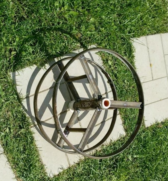
To reduce the effort when winding the hose and noise during operation, install a plain bearing in the hollow axis of the drum. It can be made from a piece of plastic water pipe with an outer diameter of 32 mm. This workpiece is clogged tightly into the axis of the drum. If there is a used plastic pipe, it is advisable to use a part of it, where a coupling half with an existing flange is welded for installation of the crane. This part of the pipe will serve as a stop for the axis and support the drum in the future.
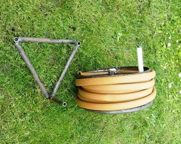
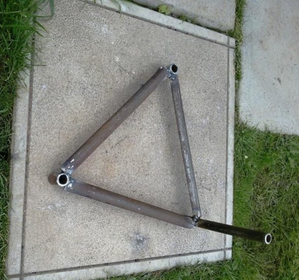
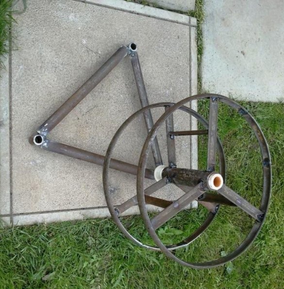
4. Making the base for installing the drum.
The base is necessary for installing a drum on it when winding and unwinding a roll of watering hose.
The base consists of three straight sections from the existing workpiece, equal in length to the diameter of the drum. Workpieces, by welding, are connected in a triangle.
Pieces of a metal pipe 1/2 ... 3/4 inch protruding downward by 20 ... 30 mm are welded to the two vertices of the triangle. (see photo). They will be used at work, as lugs.
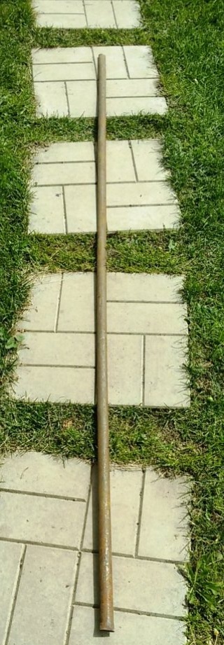
A long piece of metal pipe is welded to the third vertex of the triangle, perpendicular to its plane. It is the axis of the base and is designed to install a drum on it.
The diameter of the pipe is selected approximately to the inner diameter of the bearing of the drum axis (the inner diameter of the plastic water pipe).
The length of the axis of the base is approximately equal to the length of the bearing. The lower part of the axis also protrudes downward, beyond the plane of the triangle, by 20 ... 30 mm.
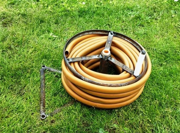
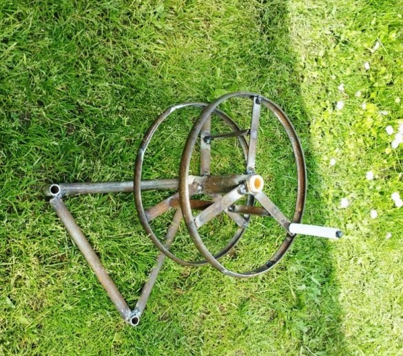
5. We assemble the device for winding the hose.
We install the drum on the axis of the base and check the freedom of its rotation.
6. For the convenience of work when winding the hose, we will produce a handle.
For the handle we use a piece of plastic water pipe with a diameter of 25 mm.
At the junction of one of the spokes with a hoop, perpendicular to the spoke, we weld a segment of the reinforcing bar with a diameter of 8 ... 12 mm and a length of 120 ... 140 mm. The free end of the rod is welded in the form of a rivet head. Adjust the size of the head to a diameter slightly larger than the inner diameter of the prepared plastic tube. We adjust the length of the tube, according to the length of the rod obtained after welding - the axis of the handle. With the blows of a hammer, we put the tube on the axis of the handle. Check the free rotation of the tube on the axis of the handle.
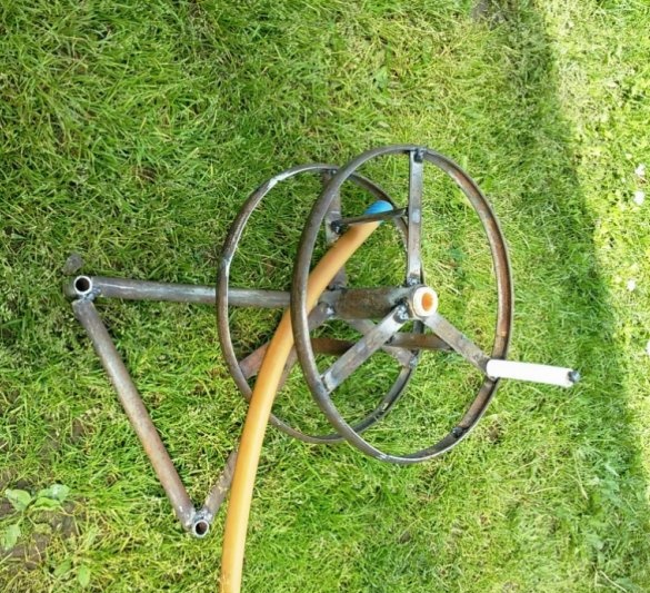
7. Using the device.
We put the base in the right place on the plot and set the drum on it. We get the end of the hose under the jumper.
Pressing the free side of the triangle of the base with your foot, rotate the drum by the handle and reel the hose.
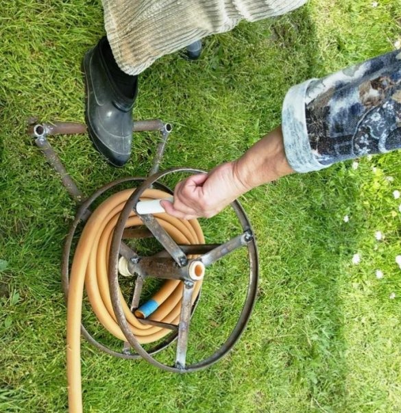
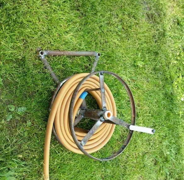
To unwind the hose, it is easy enough to pull on its free end. In this case, the hose does not twist and has no fractures.
A drum with a wound hose is removed from the base and stored separately, while having a minimum size.