» Topics » DIY ideas »The simplest color music on a single transistor

The simplest color music on a single transistor

For color music I needed:
1. LEDs 5mm green 2 pcs
2. Connector
3. Transistor kt817
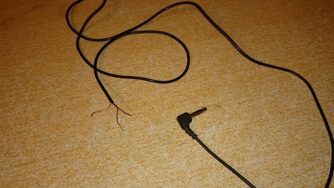
4. Unnecessary headphones.

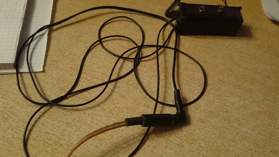
The first thing to do is cut off the liners, and see 3 wires:


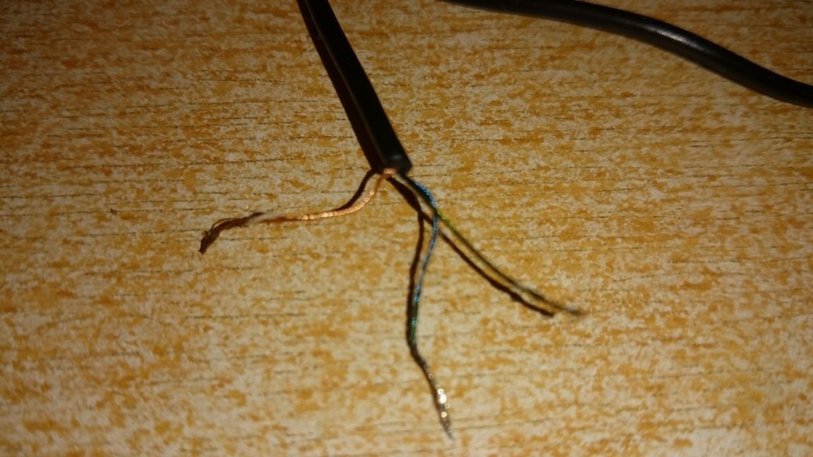
Golden in this case is the central, blue and green exits to the inserts. We need a central and one of the outputs.
We assemble according to the scheme:


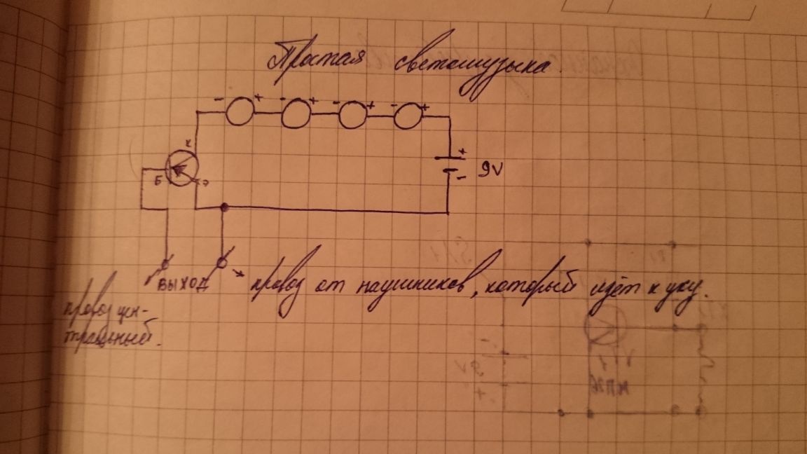
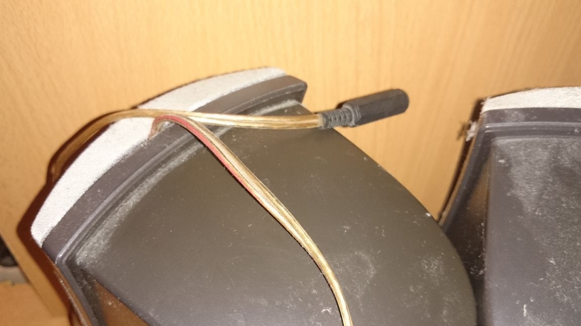
It is necessary to select a headphone jack and solder 2 wires there, then solder these two wires parallel to the speaker, at least I did so, there was no desire to include this miracle in the system unit (into the headphone jack) and parallel to the speaker, you can). The sound does not disappear. He brought out the connector under the crown-power.


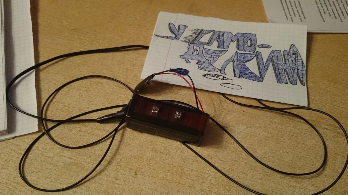
The case is made of a small box from under something, in front there is a film under the tree, around the tape is black. I didn’t want to fantasize, the case can be steeper and more fun if necessary.


Vidosik in order to make sure that the system is working:
Question \ topic is automatically published in the social. site network - stay tuned for answers there:

Suitable for topic

Related topics

Add a comment

    • smilesmilesxaxaokdontknowyahoonea
      bossscratchfoolyesyes-yesaggressivesecret
      sorrydancedance2dance3pardonhelpdrinks
      stopfriendsgoodgoodgoodwhistleswoontongue
      smokeclappingcraydeclarederisivedon-t_mentiondownload
      heatirefullaugh1mdameetingmoskingnegative
      not_ipopcornpunishreadscarescaressearch
      tauntthank_youthisto_clueumnikacuteagree
      badbeeeblack_eyeblum3blushboastboredom
      censoredpleasantrysecret2threatenvictoryyusun_bespectacled
      shokrespektlolprevedwelcomekrutoyya_za
      ya_dobryihelperne_huliganne_othodifludbanclose
34 commentary
Guest Sergey
Thanks!
I have not tried it, but I think not all !!! Only those that "support work with a dimer." The rest will light up sharply and only at full brightness.
Guest Sergey
You do not know, can instead of incandescent lamps connect modern LED lamps? to thyristors KU-202?
Guest Sergey
You do not know if you can connect modern LED lamps instead of incandescent lamps? to thyristor KU-202?
Author
ahahahah, so to say, without knowing the person, the first time I meet this. Thank God that your statements are far from being erroneous.
2 Kiborg
By development - a schoolboy. In fact - perhaps study at a vocational school or technical school (or, as it is now commonly called, a college).
yes no, everything is fine)
The output transistors in the final amplifier remained alive? .... (Or ... what's there now instead of them ... microcircuits, probably ...)
2 Kiborg
But do not be rude. When you, my young friend, lied at the administration about me, they advised me in the correct form to behave more restraintly, at the same time recommending not just criticizing, but also giving some advice on how to fix it. Since it is impossible to fix the presented device assembled from the govnotext that you found, I advise you to get acquainted with the very basics of the direction you have chosen before soldering something. ;)
why do we need a transistor?) In turn, turn on the battery and use it :) I personally did this)
I’m here, like ... I passed by ... I don’t consider myself a specialist in this area, because as soon as I “grabbed the heights”, I collected the simplest receivers and color music on thyristors in my childhood ... But, I agree, even my amateurish knowledge was enough, so that the wrong designations of LEDs and the complete ignore by the author of the fact that transistors are "direct and reverse" are striking ...
Author
I’m not your author, that you are rushing here with advice
And the author of this opus, for a start, would have to read the book of Iceberg "Transistor? ... It's very simple!". And about light music - the books of Bulat Galeev, including, together with Andreev and Sayfullin.
2 Valery
One must fight the growth of entropy and contempt for the laws of physics.
2 Business
He, apparently, from your fair remark and took the type of transistor, confusing it with the author's text. But, in fact, paragraph 1 of his remarks just says that everything is confused. Paragraphs 2 and 3 of his remarks are somewhat confused and, in fact, should be reduced to one thing: neither the collector current nor the base current modes are specified.
Valery, and you’re like “Ugh!” : winked:
Author
I learned so much about myself. I’m a schoolboy in your campaign, just write about teachers. Go on, I wonder what else you’ll drag.
Well .... it starts ....: wink :: am:
Ivan, but that’s not what he writes about, the author generally recommends another transistor (I’m silent about the circuit). I recommended this 315 and 361, because there are enough for two LEDs and them (I am silent about the circuit).
2 Business
So after all Vitalik78 it is about this that he writes that everything is confused: the polarity of the battery, and the type of transistor, and its designation on the "pseudo-circuit". Everything is dumped into an incomprehensible, meaningless pile.
You are certainly right in your judgment. It seems you call yourself "knowledgeable", and write such "childish" stupidity about the inclusion of transistors kt315 and kt361. Is it really not enough that the use of these transistors entails a change in the polarity of the battery and the same LEDs? This is not even discussed at all (if you are experts).
And the device itself (: winked: even the simplest) is simply flasher responsive to the volume of the sound (signal).
And that’s not all.The mode is not set either by base or by collector; the type of transistor in the circuit and in the text does not match; the designations of the transistor and LEDs are incorrect; there is no capacitive isolation with the sound source; the number of LEDs in the text and on the "circuit" does not match; the screen is called the central golden wire; source of "schema" is not specified.
looked and the same a couple of questions arose: Correct me.
1- if the PNP transistor (kt361) is drawn in the circuit, then the Emitter doesn’t have any “-” batteries! If KT315 is taken, I remove the question, but it is not drawn correctly. (arrow on the contrary)
2- The maximum voltage of this trans. The base emmitter holds up to 4 volts. And on headphones MAY be issued and more (maybe not in your case, depending on which amp). NO Current limit. resistor in the BASE circuit at least at 470th.
3- in the event of a breakdown (nothing lasts forever) - shorty is possible (if it does not break the transition).
Kiborg,
Firstly, I’m not “supposedly”, but actually criticizing the fact that you don’t know how LEDs and transistors are designated, that is, the very basics of electronics.
Secondly, I see what you found on the Internet and crookedly redrawn the diagram. In a decent society, it is necessary to give a link to the source of borrowing, otherwise it is called plagiarism, that is, the appropriation of someone else's intellectual property.
Thirdly, according to your article and your correspondence it is quite possible to say not only that you do not know electronics, but also that you do not know Russian. If you are embarrassed to ask your Russian language teacher for help, then learn how to at least use the spellchecker.
Fourthly, it is not necessary to mislead people that you enjoy the view of this “miracle” for 3 hours a day for four years. And the fact that the device, under a successful set of circumstances, can work for some time, I did not deny, only this cannot indicate its reproducibility.
Fifthly, I see my mission in being a "forest nurse", helping the site administration in identifying bullshit. Understanding people see everything, they just don’t have time to expose fake devices. And beginners should be given truthful information about what will work and what will not.
Author
Firstly, I’m wondering why you wrote down the entire chat here, allegedly criticizing, as it seems to you: due to the fact that my LEDs on the diagram are not drawn according to GOST? due to the fact that the development is not mine?
Secondly, why did you get that this is my drawing of the circuit, suddenly I found it on the Internet?
Thirdly, you undertake to judge my knowledge / not knowledge in electronics, according to only one article.
Fourth, you predict the short-term operation of this device, without even suspecting that I made it 4 years ago, and posted it only yesterday, and all this time, you will not believe it works stably, using 3 hours a day.
Fifth, all of your comments are judgmental, including in my article, while you yourself have not a single article. It’s easy to sit and cherish each article without doing anything yourself. That's all.
From the fact that you drew the diagram as it suits you, it did not become correct. Other people may believe you and try to reproduce your “device” in this way, resulting in disappointment.
Author
Well, that’s the name "simplest" on one transistor, but about color and light, yes, I mixed it up.
This is most likely LIGHT music. The light just lights up to the beat. And COLOR music is when color separation. I remember when I was developing my design of color music, I had to put a compressor on the input, because the range of amplitudes from the amplifier is large ... And the color separation filters on the op-amp
Author
Thanks for the comment, Ivan, appreciated your stupidity. The scheme is drawn as it suits me. Your hasty conclusions are completely false.
The scheme is drawn with gross errors.The so-called "author" tore this bullshit, not understanding in the electronics of either an ear or a snout, from the same delusional text.
I once collected color music on KU-202N or KU-201K teristors. Then the finished ones were sold. And now for some reason it’s “not held in high esteem” ... A bunch of blinkers are on sale, but such as then, so that red under the bass, green under the middle, blue under the high, now, for some reason, no .... Still yellow in the backlight when the rest go out ....
: winked: Well, what is light music, just a dumb flasher. The transistor is any low-frequency.
315, 361, ..... a bunch of these.
can I have a photo of the transistor

We advise you to read:

Hand it for the smartphone ...