

We will make a simple, but very useful and effective water level indicator ourselves. And this article will help you do such a necessary and very useful thing.
To begin, consider the circuit diagram of this device.
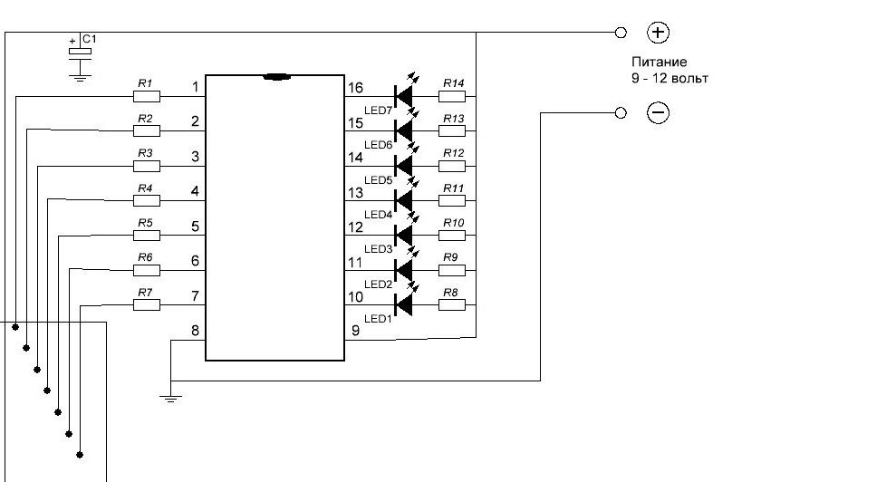
Water level gauge diagram.
The circuit is very simple, but it works great. At the end of the article there will be a video where the operation of this water level indicator, which we will do together with you, is clearly shown.
To get started, we will collect the parts that we need to make the device.
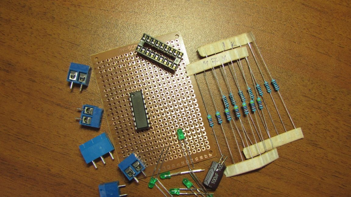
Details for the manufacture of a water level indicator circuit.
We will need:
Microcircuit ULN2004 or similar, a contact pad for installing the microcircuit on the board. If there is such a platform, there is no risk of overheating the legs of the microcircuit with a soldering iron or damage its internal device by static electricity. And repair of the circuit, if necessary, is reduced to a few seconds. It is enough to remove the burned microcircuit from the socket and insert a new one in its place. A solid benefit, especially for not very experienced hams.
Resistors R1 - R7 - 47Kom.
R8 - R14 - 1Kom.
LEDs of any color of your choice, with a diameter of 3-5 mm.
Capacitor 100Mkf 25v.
Terminal blocks of any type, or even without them at all, but the usability of the device will decrease slightly.
Any breadboard, if only all components fit. I use such boards because I don’t want to bother with making a printed circuit board, it’s just more convenient and more familiar to me.
All the components are assembled and proceed to the manufacture of our device.
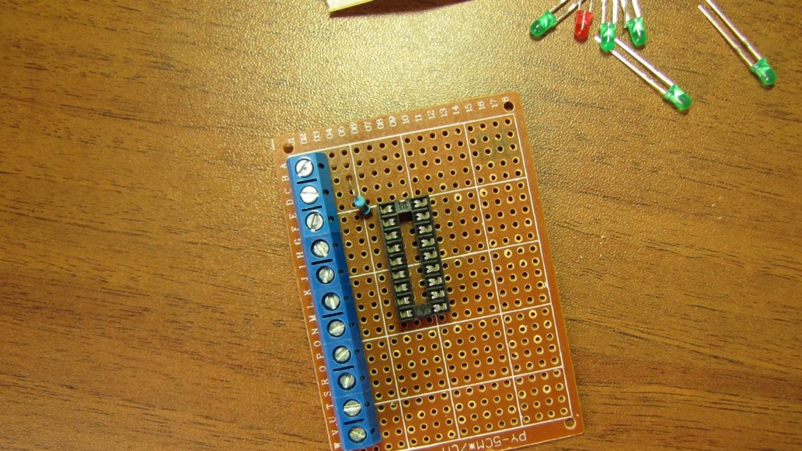
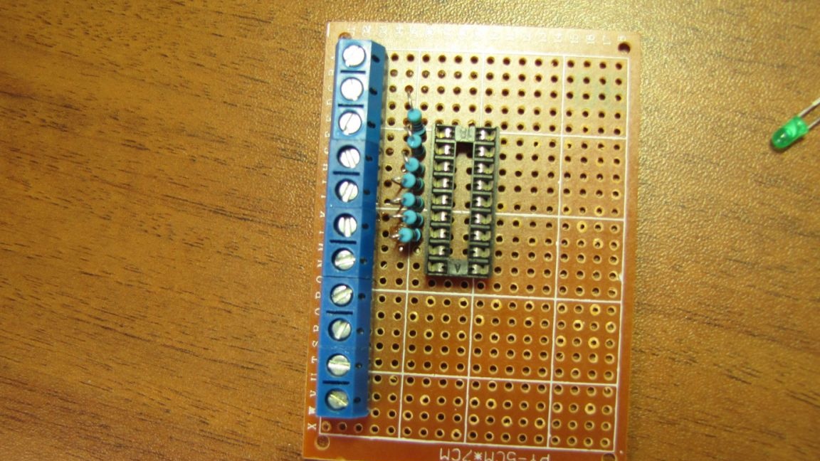
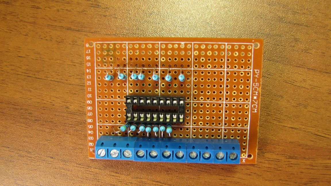
We place part of the components on the board.
Immediately solder the installed parts, otherwise they will constantly pop out of the sockets.
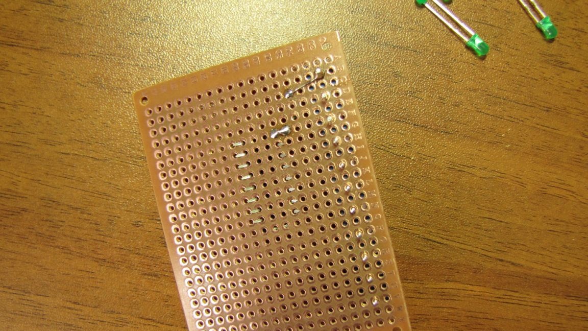
Sealing parts in turn.
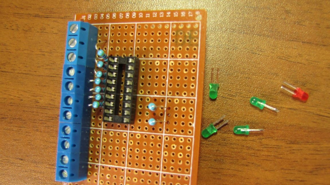
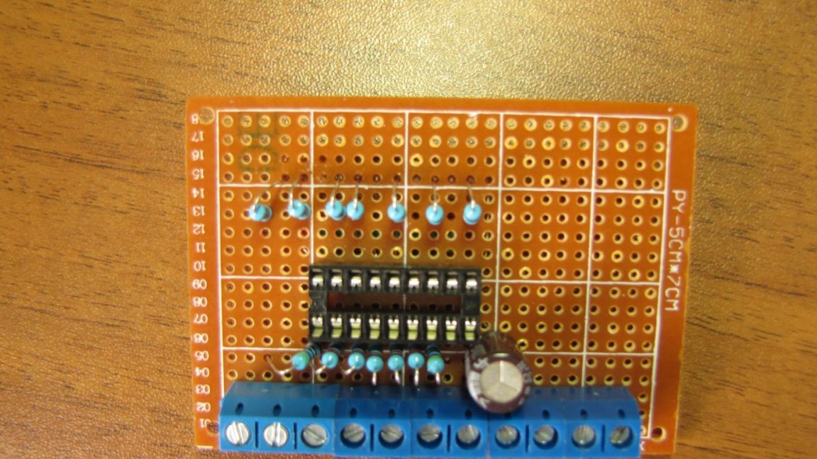
Install the following circuit details.
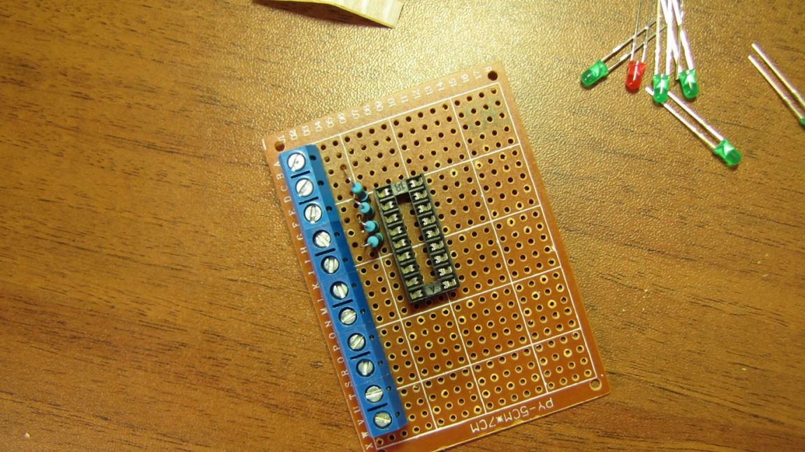
There is no system, work as you prefer and easier.
You just need to constantly check the scheme, no matter how simple it is. Everyone can get confused, but I don’t want to redo the work already done.
Accuracy and attentiveness are also not superfluous.
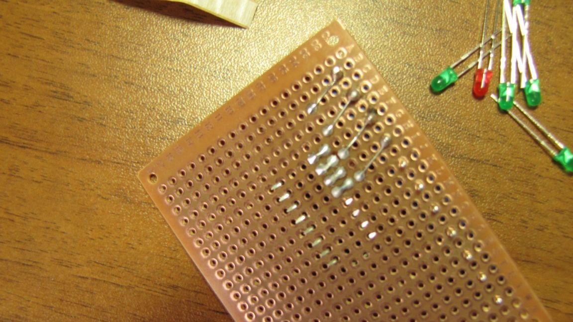
And so in order. We install the part, solder and move on to the next.
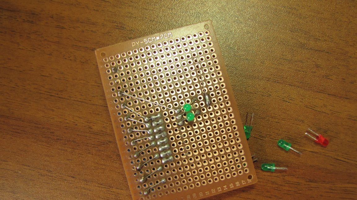
We are approaching the finish line.
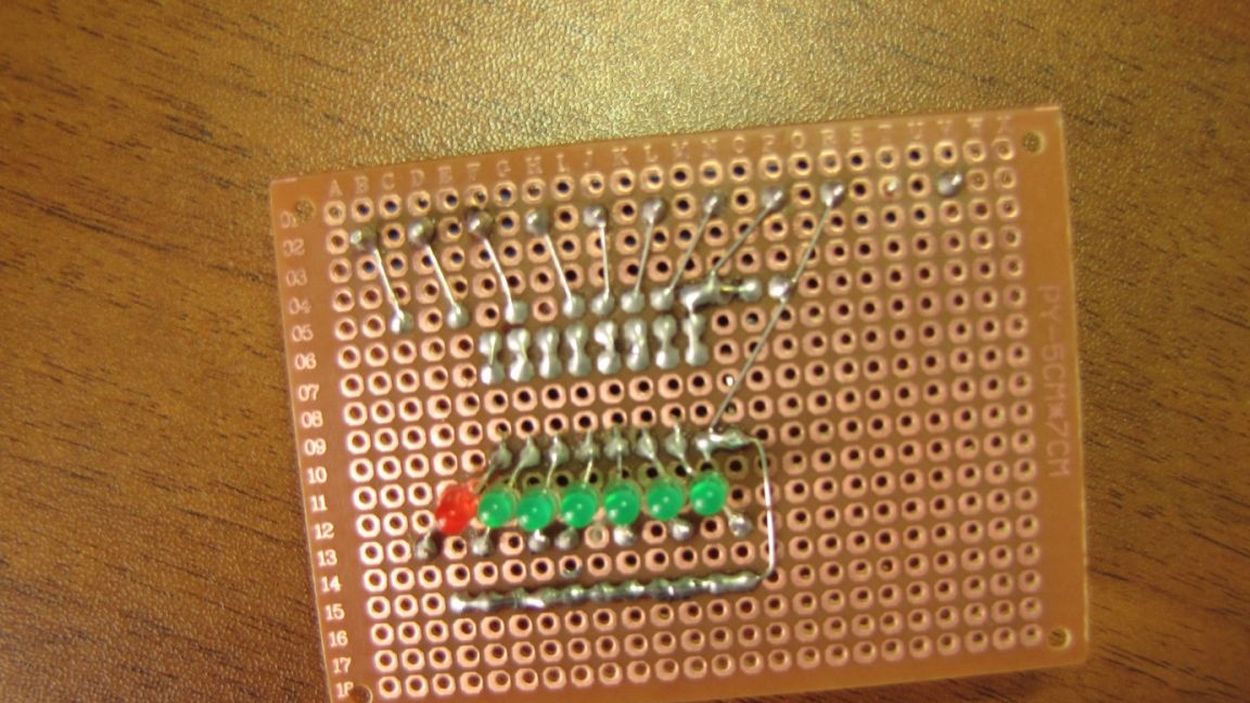
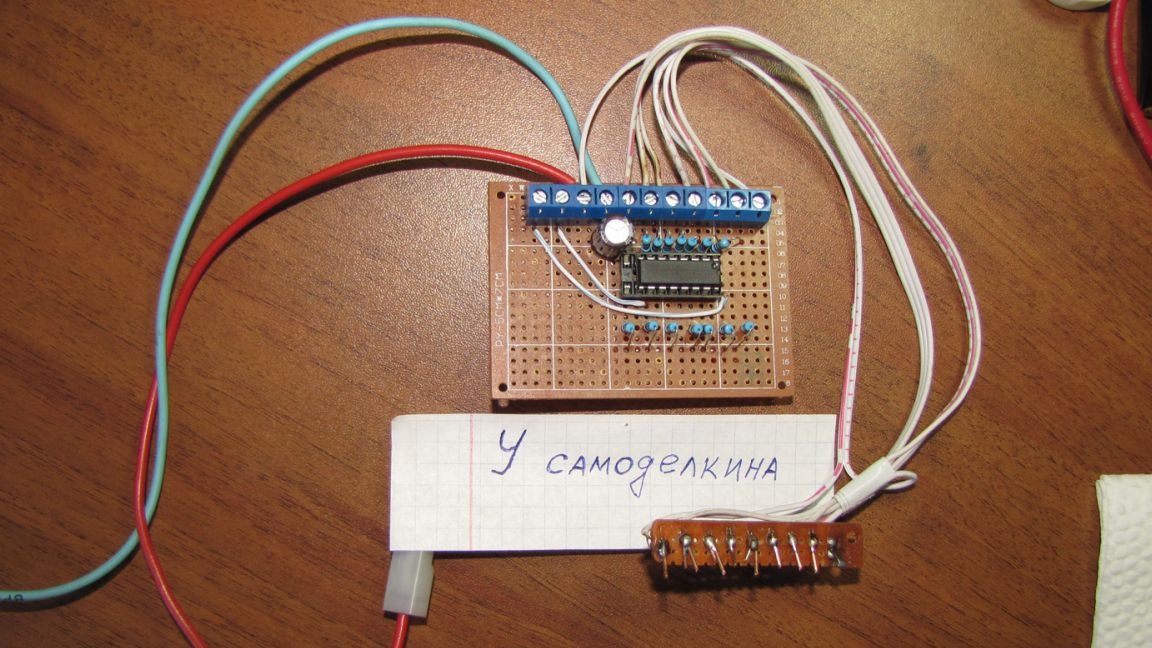
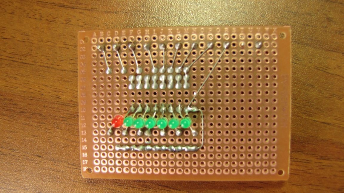
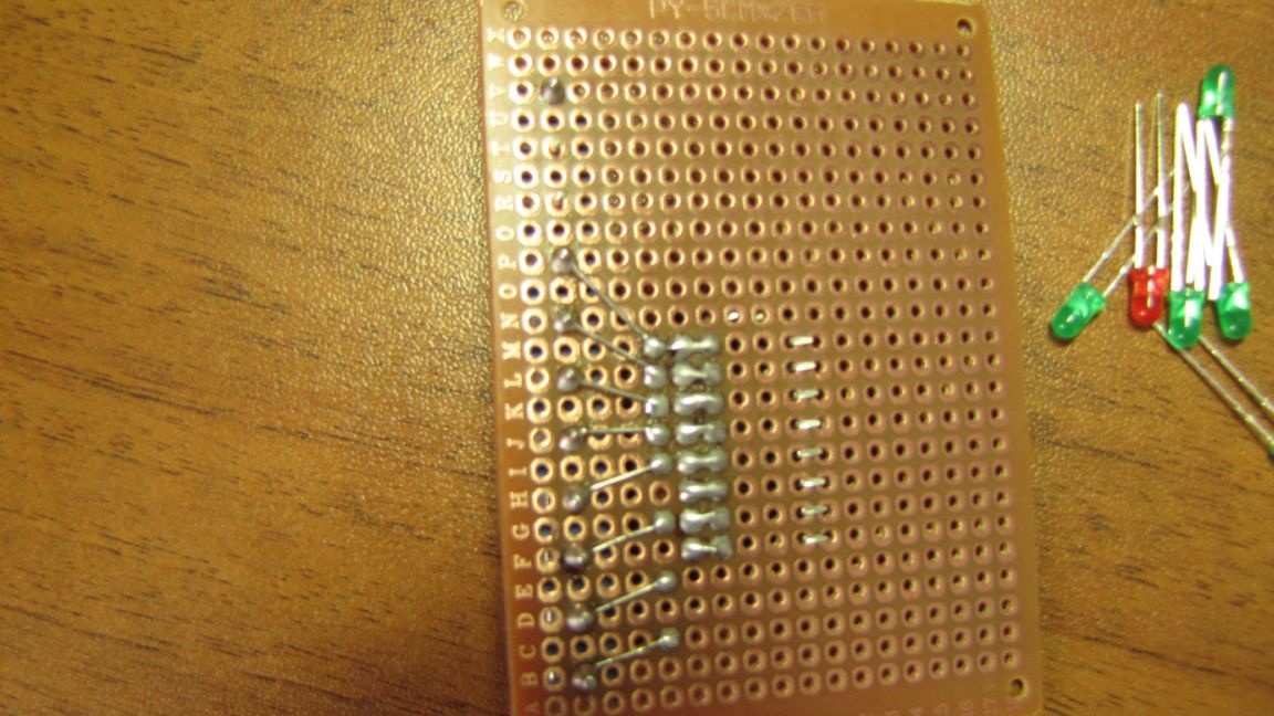
I installed the LEDs on the back of the board only because this block of the water level indicator circuit will be installed in the control panel on the front panel. The panel will be drilled under the LEDs, and the outline of the container will be drawn outside. And the presence of the amount of water will be visually displayed on the shield.The board locks onto four bolts in existing holes.
This is the first ready-made element of the future system of water purification from iron, bacteria, all kinds of harmful impurities and other “kaki”. The system in my house has been working for almost three years, has proven to be reliable, convenient and in general I like. I am completely satisfied with the quality of water. But the time has come for modernization. There are new requirements (for me), I want a more convenient service, I want all the information about the system to be constantly in front of my eyes. I built the first water purification system without any experience and made some mistakes, which I will certainly write about in the following articles, but in general there were only two minor breakdowns. I am to blame for one failure, and not a high-quality component product in the other (again, I am to blame, I saved a little and bought not what followed).
All equipment will be blocky (so the possibilities of modernization increase and repair is simplified), as cheap and simple as possible, so that many can repeat it.
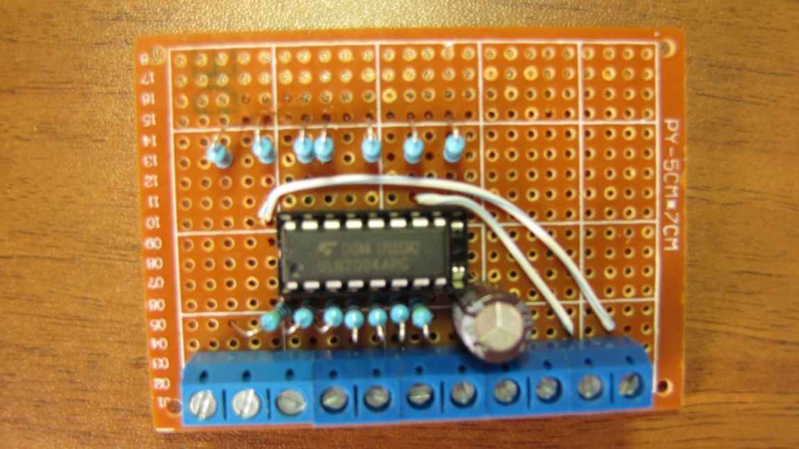
Why do I need white wiring I will tell in one of the following articles.
The water level indicator (indicator) is ready.
The cable that goes to the level sensors can be supplied with any eight-wire signal, they are now sold by everyone in different stores that deal with alarms, electrics. Cross section and cable length do not play a special role. There are very thin and cheap cables.
How to make level sensors, you need to think and make at the place of application. The sensor contacts are best made of stainless steel. A positive common electrode needs a massive one. I made from a small stainless spoon, the electrode works fine and is completely resistant to electrochemical dissolution. Places where the wires are soldered to the electrodes are best insulated with the help of any glue gun (they are reliably preserved from dissolution).
However, if you feed the circuit using the button without fixing, then there will be no dissolution. You need to see how much water - I pressed the button. He released it and the circuit power turned off. At the cottage, the circuit power can be used from batteries or finger-type batteries connected in series, and with a button (enough for a long period) or from an old battery. This device is not demanding on the supply voltage.
Good luck to you.
Please share on social networks, if you are not sorry, maybe someone will also find this simple, but necessary thing in the household useful.
Watch a video of the water level test.