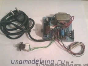
Hello dear friends and "the inhabitants of our site". I want to bring to your attention another device for checking the performance of thyristors. It can be assembled from typical radio elements available in the workshop of each radio amateur. Here is a diagram of the device
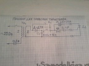
The voltage of 6.3 V is removed from the secondary winding of the transformer TP1 at a load current of about 0.5 A. A constant or alternating test voltage is selected by switch B2. Thyristor electrodes are connected to the device using crocodile clamps. The thyristor serviceability indicator is an incandescent lamp 6.3 in 0.28 A.
First of all, we check the thyristor with direct current. For this, switch B2 is set to the lower position according to the scheme. If the button Kn1 is not pressed, then with a functioning thyristor the lamp L1 should not burn. When the contacts of this button are closed, the switching voltage will be applied to the thyristor control electrode. It will instantly switch from closed to open, and power will be supplied to the L1 warning lamp. After releasing the button, the lamp remains on. To turn it off, you need to remove power from the anode of the thyristor. To do this, test the thyristor with alternating current.
Switch B2 is moved to the upper position according to the diagram. Now the control lamp will be turned on only when the button Kn1 is pressed, since when the contacts are open, the first negative half-wave of the alternating current will turn it off. If the thyristor is broken, the control lamp will light when the button is not pressed, both from alternating and from direct current. If there is a break in the thyristor, then by no means will it be possible to turn on the control lamp. The rectifying diode can be any, for a current of 300-400 mA, for example, D7A - D7ZH; D226; D229 To assemble this device, we need the following parts and tools.
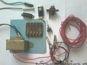
1- step-down transformer 220 / 6.3 V, power cord with plug, 2A fuse and its holder; 3-position switch; diode D7A; electrolytic capacitor 1000 microfarads at 16 v; button; resistor 47 room 0.5 watts; bulb 6.3 in 0.28 A; toggle switch. 2 - soldering iron; solder; tweezers; mounting wires; pliers; nippers; drill; drill. We assemble as follows.
Step 1
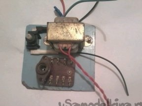
First, we install a transformer, fuse, switch B1, switch B2, and a mounting plate measuring 5 by 3 cm on a getinaks strip measuring 10 by 10 cm.
Step 2. We solder the entire circuit of the device. Check the correctness of the assembled circuit.
Step 3
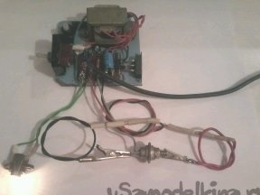
We connect the tested thyristor to the device using the crocodile clamps. Switch B1 energizes, switch B2 put in the lower position according to the scheme, press the button Kn1, the lamp L1 should light up. And then we perform all the actions described above. If the circuit is assembled correctly, then the device works, and if not, then check the correct assembly of the circuit. Such a device has been working with me for 10 years. It’s easy and fast to check thyristors. For the sake of experiment, I have assembled such a device for you to show how it works. Solve your friends the inhabitants of our site, do you need such a device or not.
