

In this design used:
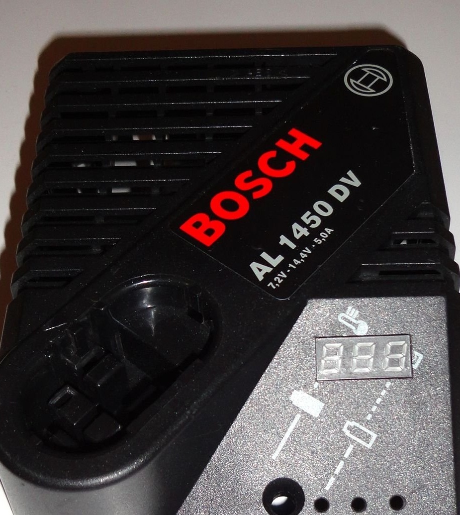
- housing from the Bosch AL1450DV charger
- battery case Bosch Ni-Cd 12V 2Ah
- fragments from the battery case Bosch Li-ion 14,4V 4-5Ah or 18V 4-5Ah
- Bosch Li-ion 14.4 V Battery Indication Module
- fiberglass foil one-sided
- batteries with high discharge current 4pcs
-
-
-
- fan 30x30mm 12V 0.05A
- transformer for 17-20V 3,5-4A
- a piece of plastic 6-8mm thick
- mounting wire
- heat shrink tube
- Super glue
- electrical tape
- transparent tape
- double sided tape
- radio components according to the scheme
- stands for boards with screw thread 3mm
Further and more detailed characteristics of the parts in the course of description
Of the tools used:
- drill
- MFI type "Dremel"
- soldering iron
- thermo-glue gun
- screwdrivers, wire cutters, etc.
Making a charger.
Schematic diagram of the charger.
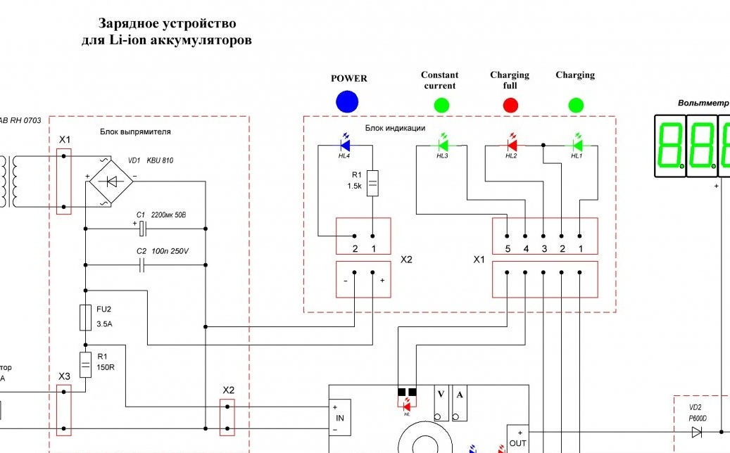
I used the transformer from some old charge with the marking 97660-215-AB RH 0703 (I have exactly the same in the linear laboratory power supply, which quietly gives out 3.5A open circuit voltage at the transformer output 18.3V has a built-in thermal fuse).
Rectifier block.
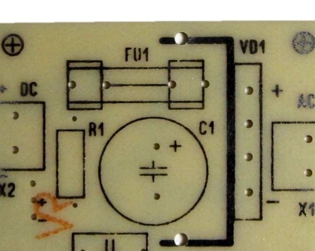
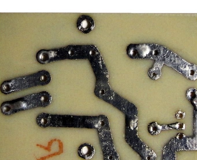
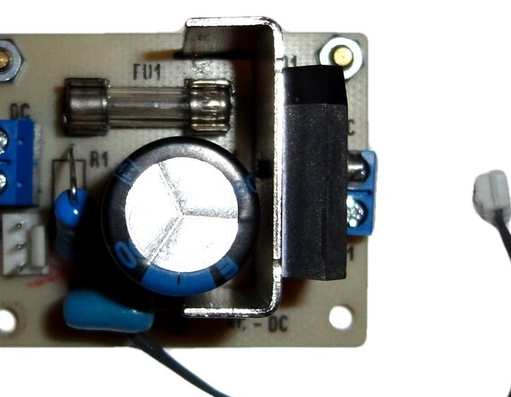
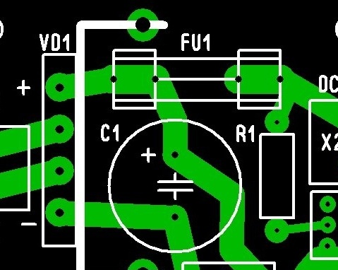
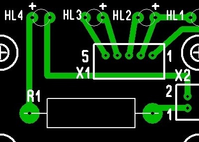
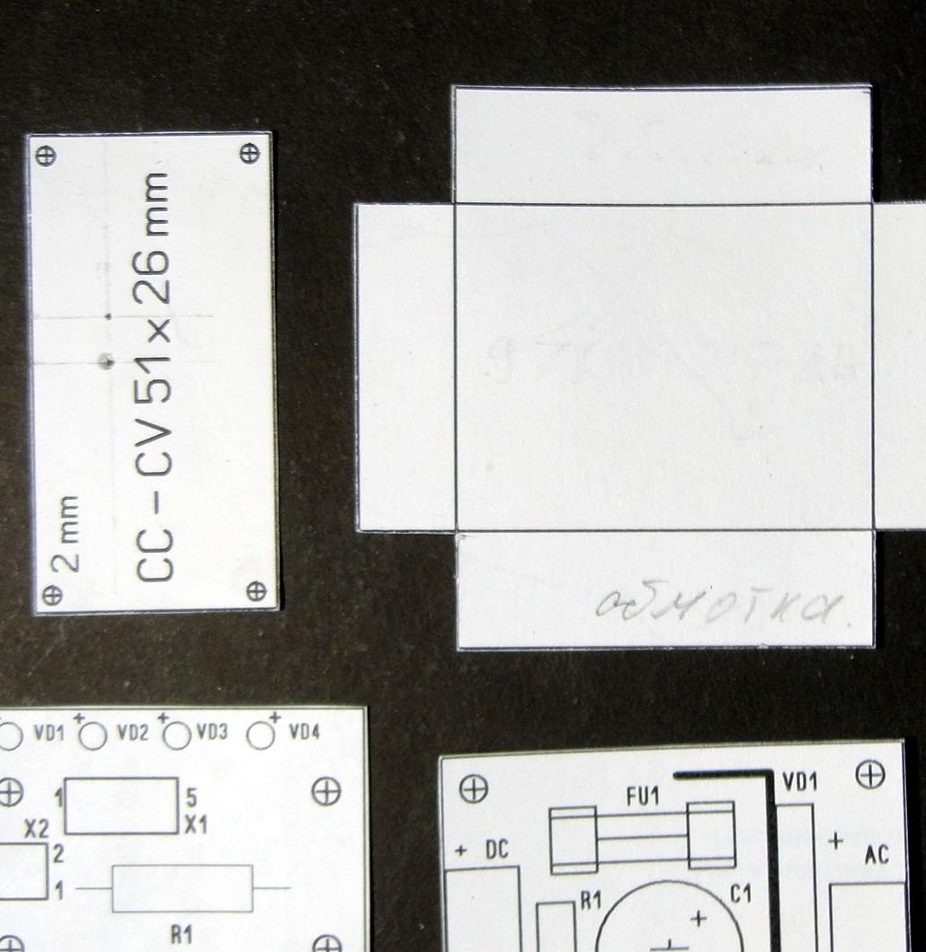
In the rectifier unit there is a KBA810 8A diode bridge on a small radiator. For ease of installation, terminal boards and a connector for a fan (from computer trash) are installed on the board. A wire with a connector on the HL4 "Power" LED is also output. The size of the printed circuit board is 40x50mm (see photo).
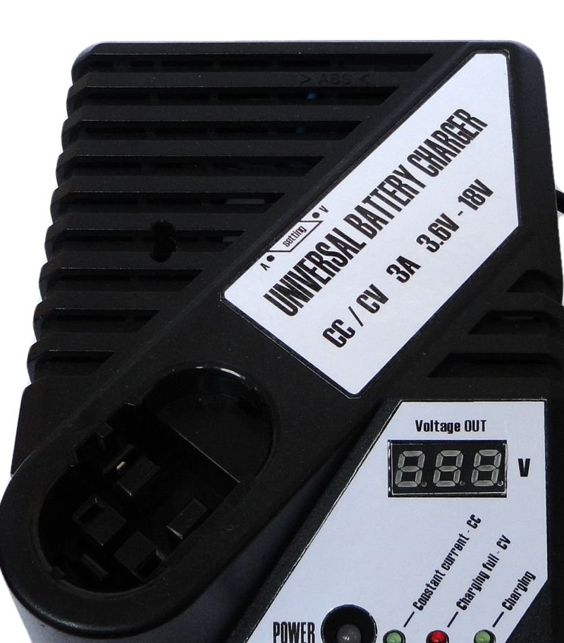
Display unit.
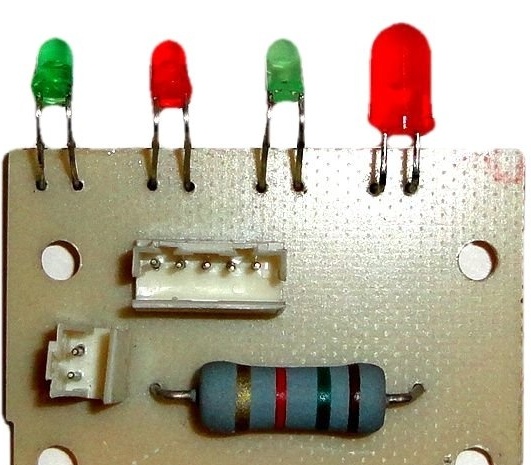
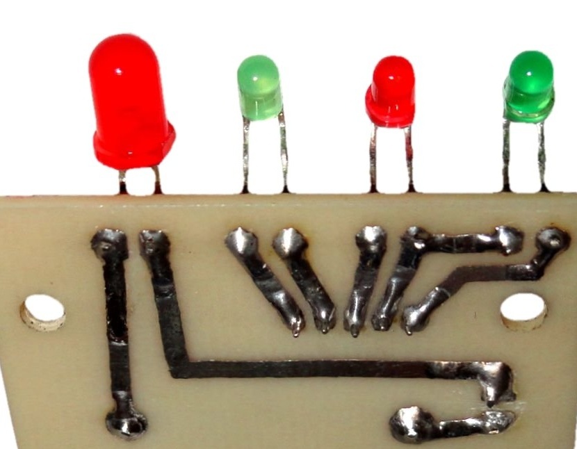
The display unit is made on a printed circuit board measuring 30x42mm. 5mm Power LED (it is red in the photo, but at the end of the assembly I changed it to blue), the remaining 3mm LEDs (see photo).
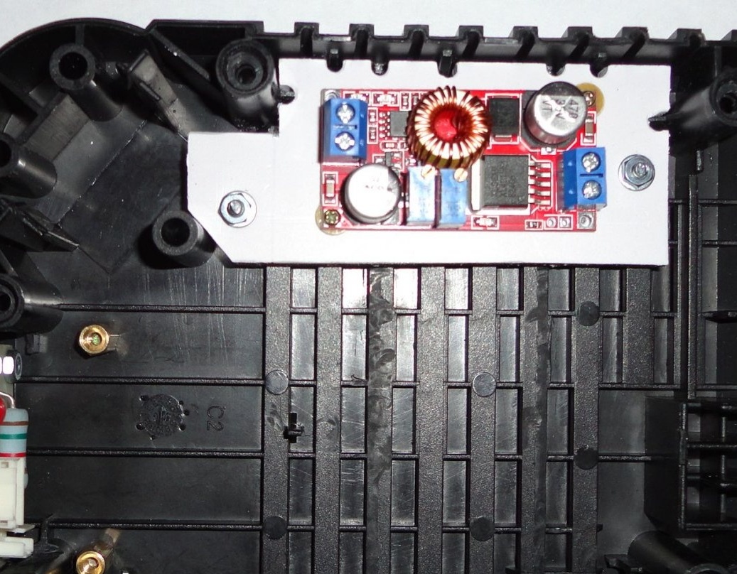
Chinese converter module DC-DC CC / CV 5A to use XL4015E1 ().
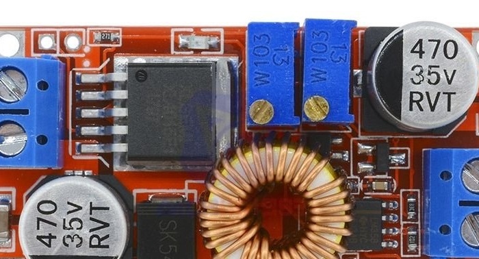
SMD LEDs are removed from the module.In their place, wires are soldered, which through the connector go to the LEDs (3mm) of the display unit (see diagram).
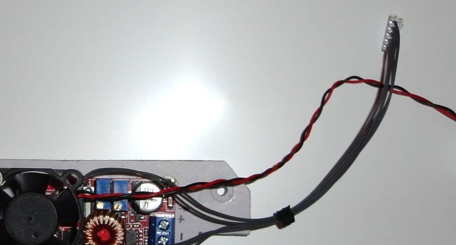
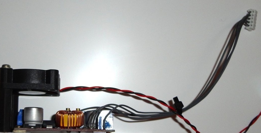
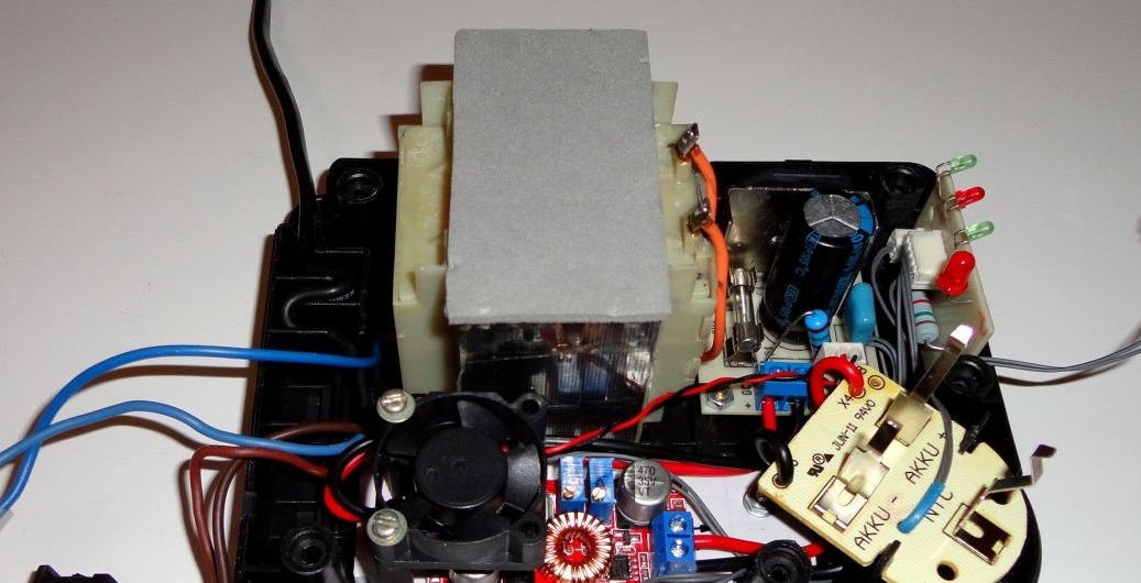
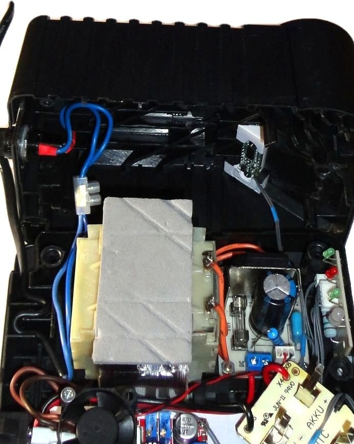
This module with screws 2mm, through textolite washers mounted on a plastic platform with a thickness of 8mm. The dimensions of the platform depend on the dimensions of the transformer. On a platform on metal racks 22-30 mm long, a fan 30x30x20mm in size is attached, which is connected through a connector to the rectifier unit. I did not make any special holes for ventilation since there are enough ventilation slots in the case (see diagram, photo).
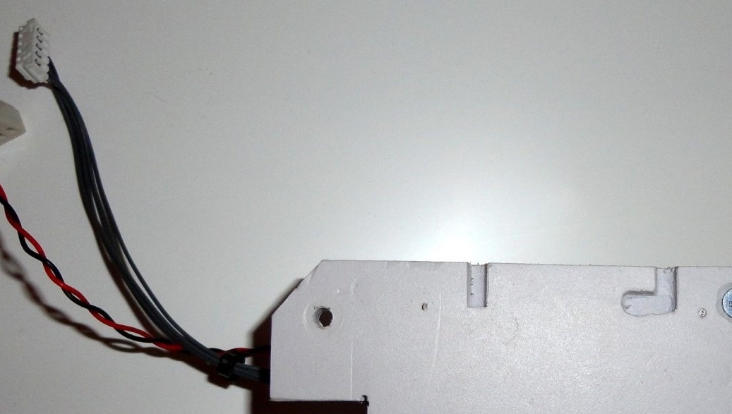
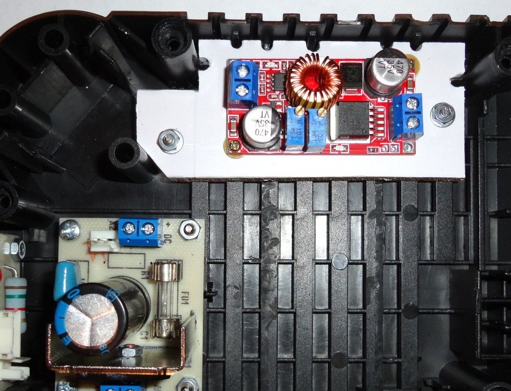
Next, the platform with the help of M3 screws is attached to the base of the case (see photo).
At the base and upper cover of the housing, according to the transformer stencil, using MFI with a mill, the partitions are cut to the desired depth. Then, when closing the case, the transformer is fixed in its designated place. Then, racks for the rectifier board and display unit are attached to the base of the case (see photo). The screw caps of the display unit are sealed on the outside with self-adhesive furniture plugs in black.
Then we fix the rectifier block (see photo).
On top and bottom of the transformer we glue self-adhesive shock-absorbing gaskets (used for legs of furniture).
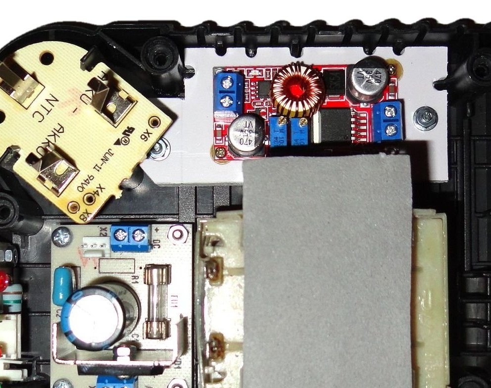
In the photo with the layout of the modules, the fan is not indicated (for the convenience of visibility of the fasteners).
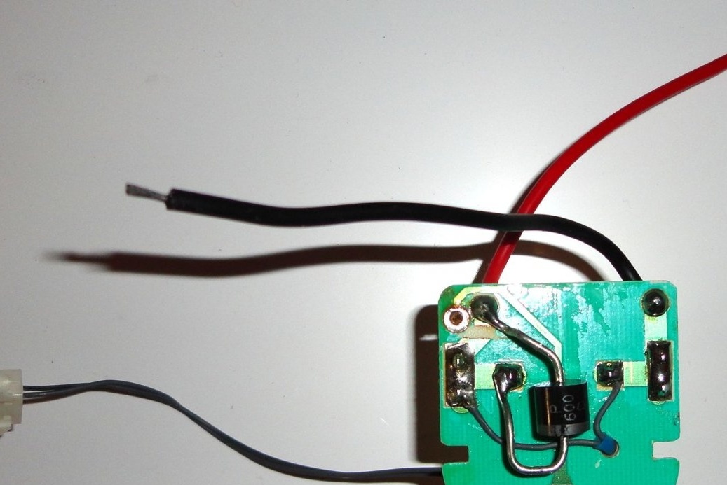
Contact block.
On the contact block, on the back, a VD2 P600D 6A 200V diode is installed, which cuts off the reverse current from the battery. A wire with a connector for a voltmeter is also output from the contacts (see diagram, photo).
Holes for LEDs, a fuse holder and a window for a voltmeter are made on the top cover of the case. A cut is also made for the switch. MFI cutter removes protruding protruding parts and partitions that interfere with installation. On the edges of the window for a voltmeter, two strips of plastic 8 mm thick are glued with superglue.
Chinese voltmeter module ().
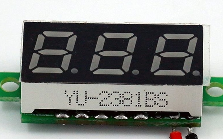
In plastic strips with a mill, recesses are cut under the “ears” of the voltmeter, adjusted to the desired depth. The voltmeter is attached with two 2mm screws (see photo).
Now the wires are neatly stacked and the corresponding connectors are connected. The switch is connected using 4.8mm knife sockets. Therefore, the switch can be replaced without opening the case. The fuse holder is connected using the terminal block (see photo).
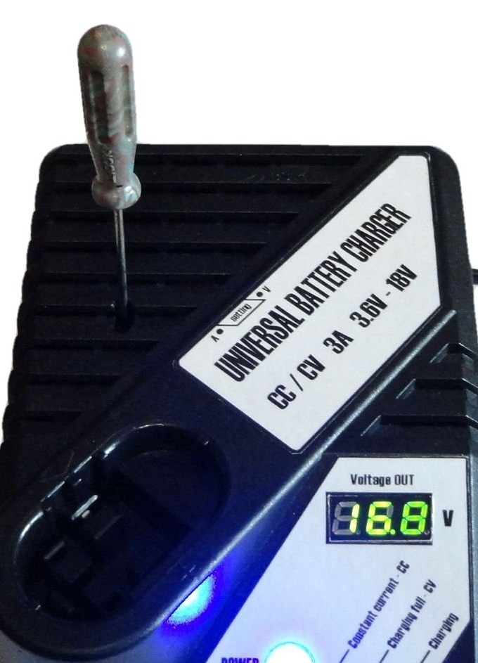
A hole for a thin screwdriver is made in the upper case cover opposite the tuning resistors. For reconfiguration of voltage and current without opening the case.
Information stickers are printed on the printer. Laminated with transparent tape. They are glued to the body with double-sided tape.
Before assembling the housing, the accuracy of the voltmeter readings is checked. If necessary, the voltmeter is adjusted.

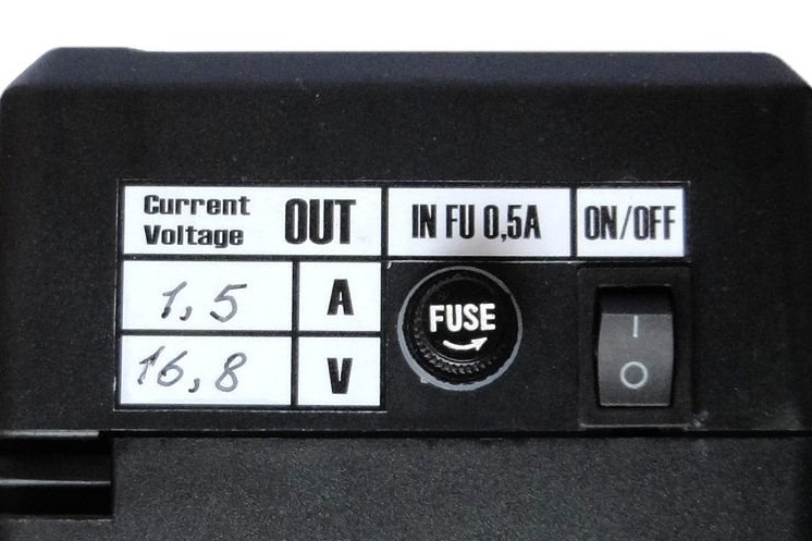
On the back sticker, the current and voltage values are entered with a marker for CD, it is easily erased with alcohol. This is very convenient in case of reconfiguring the memory to other parameters.
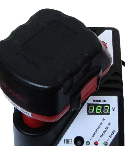
After turning on the charger at idle, we set the required voltage (16.8V).
Next, with the help of an ammeter we set the required current (1.5A). As a load, I used a car lamp.
I do not describe the exact layout of the fasteners as I immediately marked out in place, using paper stencils and in specific cases it will depend on the size of the transformer and fan used.
Making the battery.
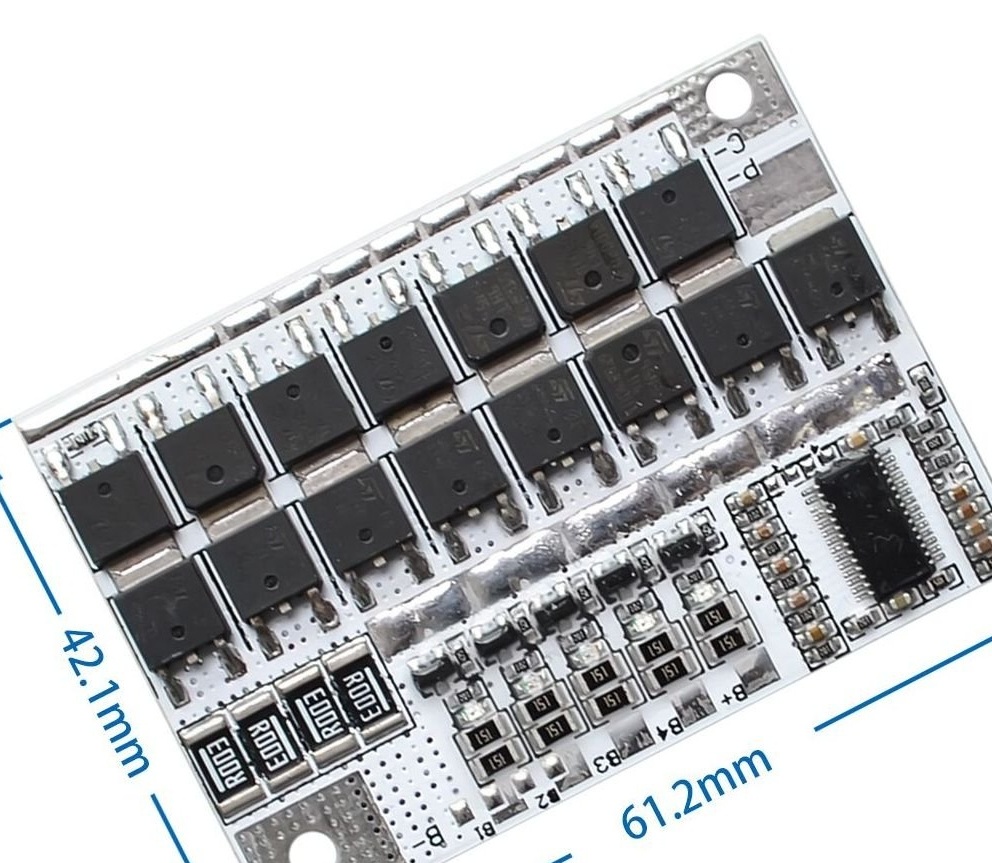
The battery uses a universal Chinese battery control and balancing module with a balance indication BMS 3S-5S 100A. This module has a large protection operation current, has short circuit protection, overcharge protection, overdischarge protection, has the ability to connect a thermistor (10K) to protect against overheating, an indication of the balance of each battery and a bunch of positive reviews on the Internet ().
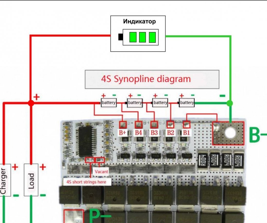
Battery circuit.
The battery used 4 batteries 3.6V 2.5Ah (I had used).
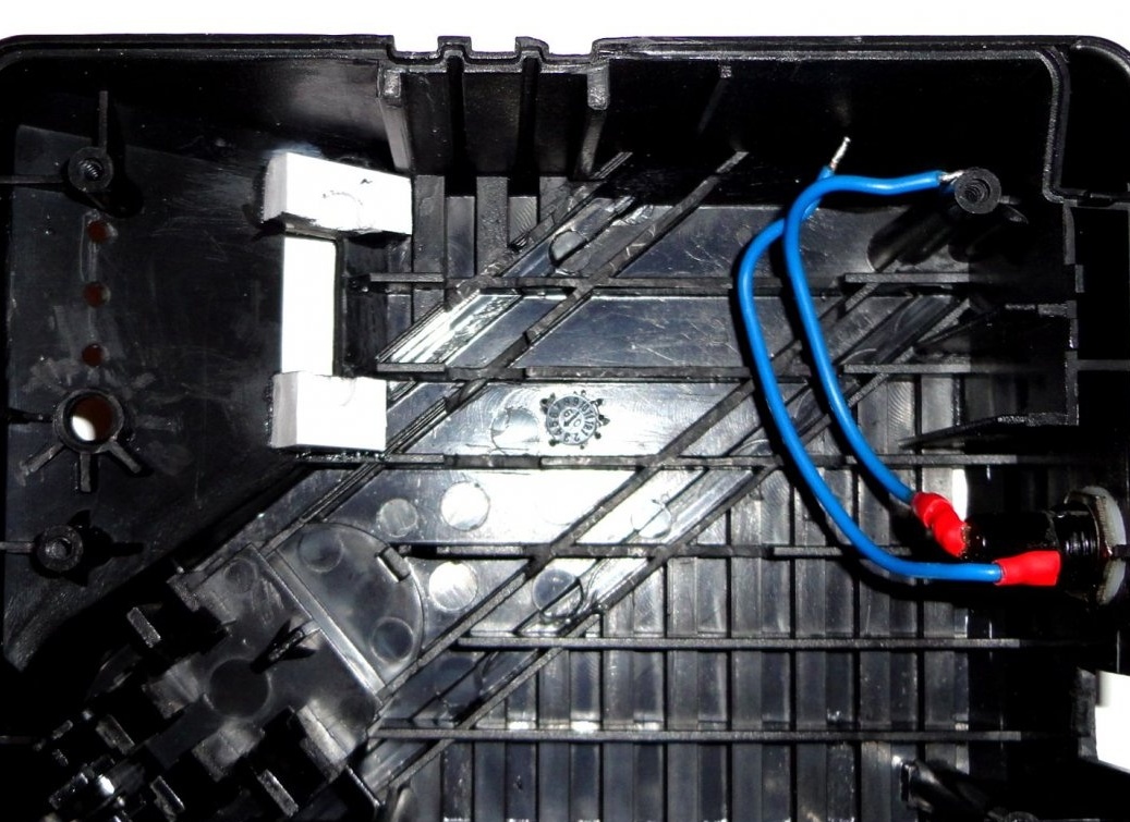
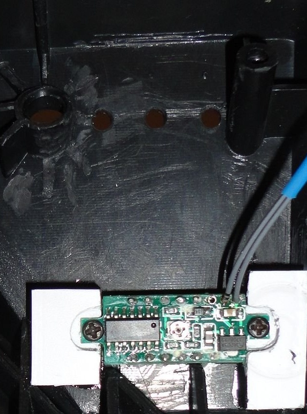
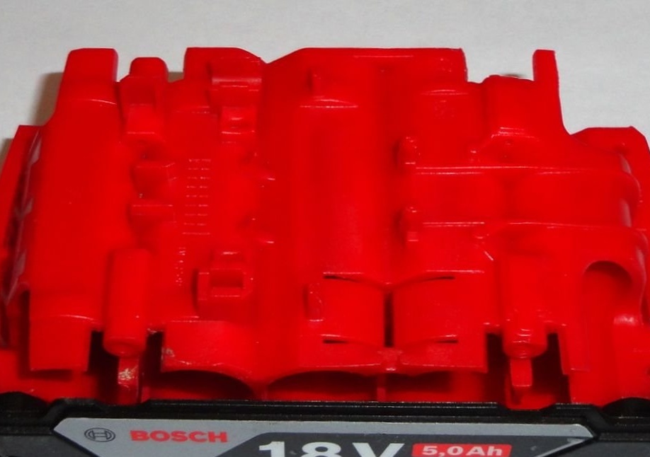
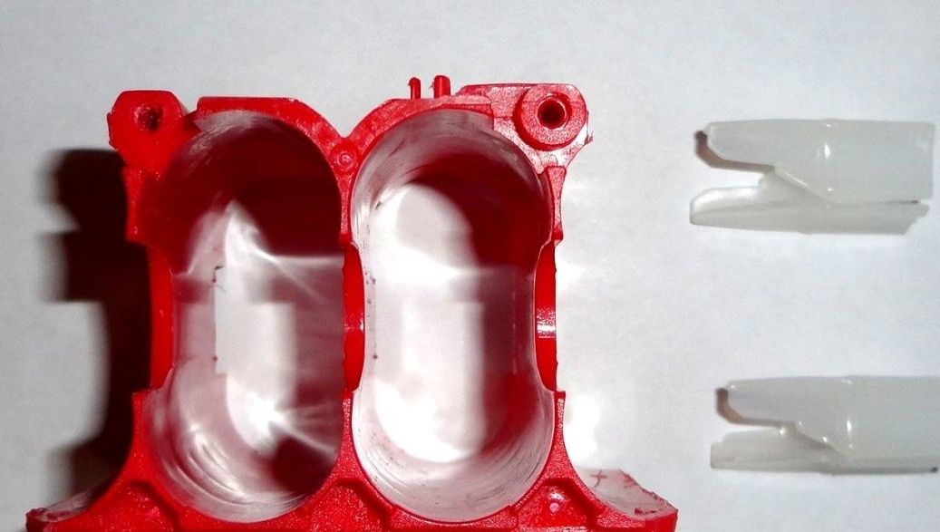
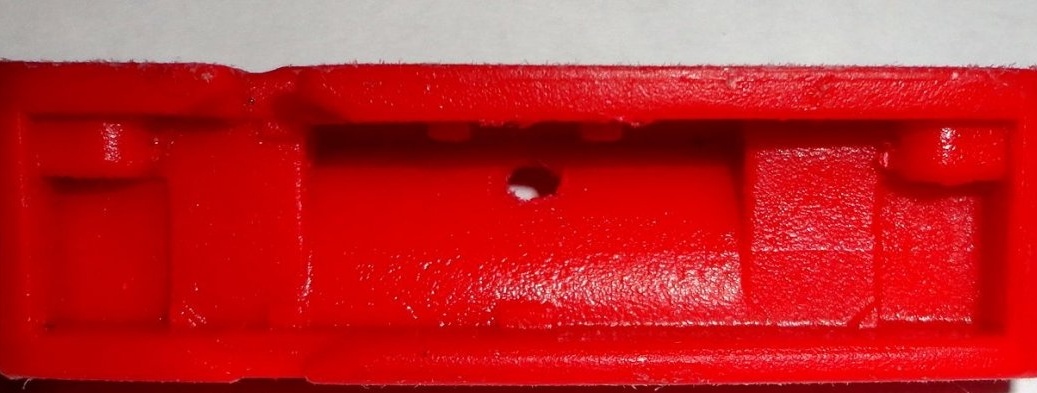
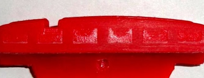
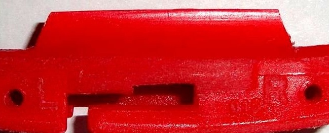
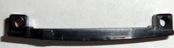
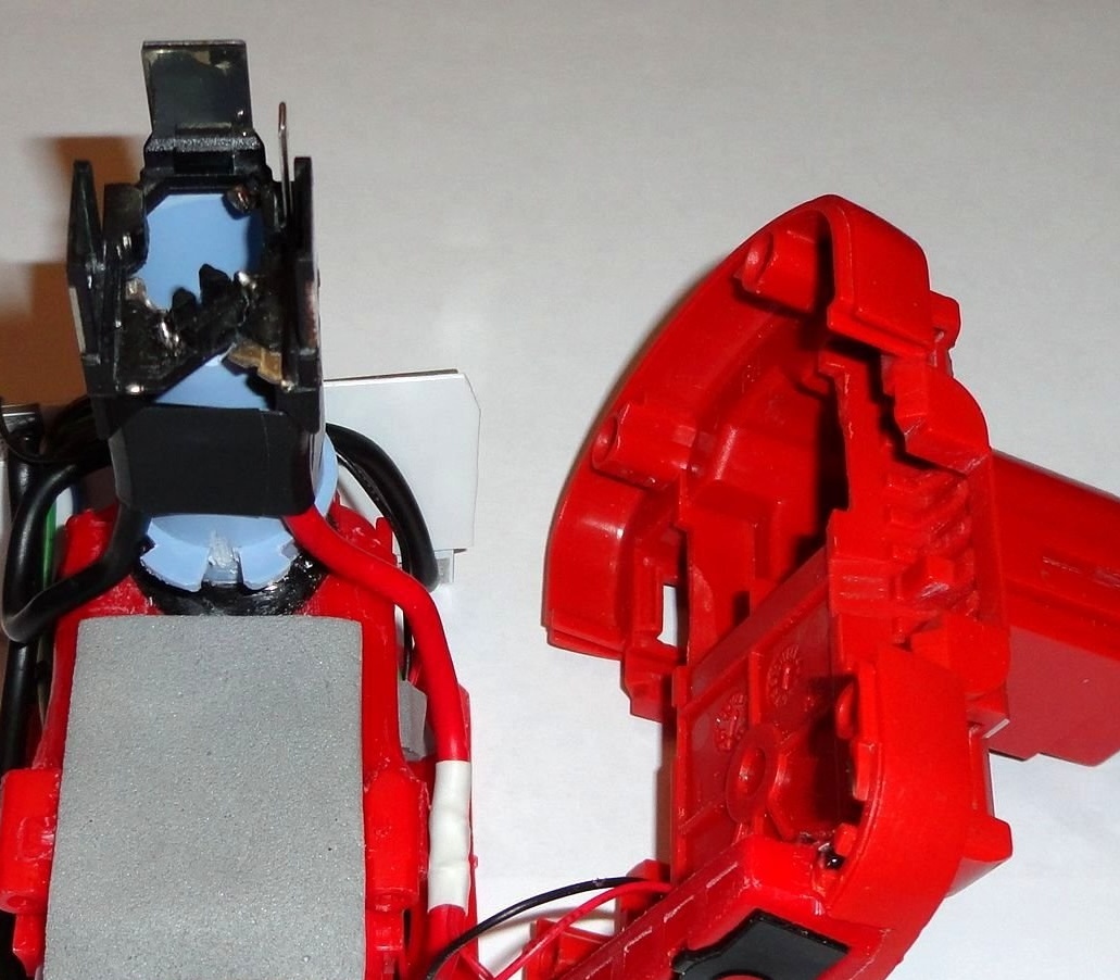
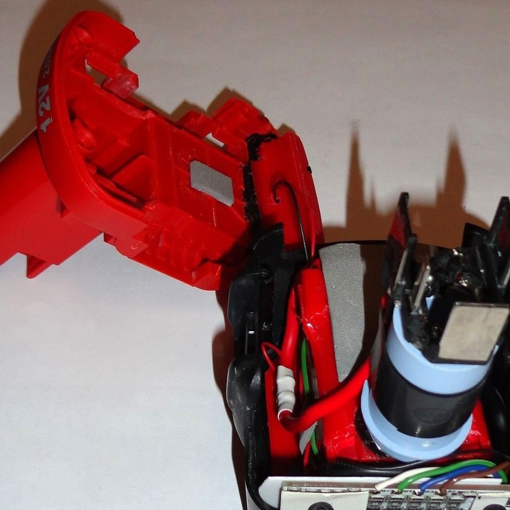
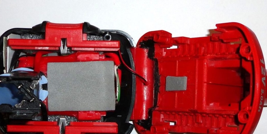
From the “killed” Bosch Li-ion 14.4V 4-5Ah or 18V 4-5Ah battery, part of the base is cut out, a fragment of the front of the case and fragments of the indicator mount are removed. You will also need 2 plastic wedges to fix the batteries in the new unit (see photo).
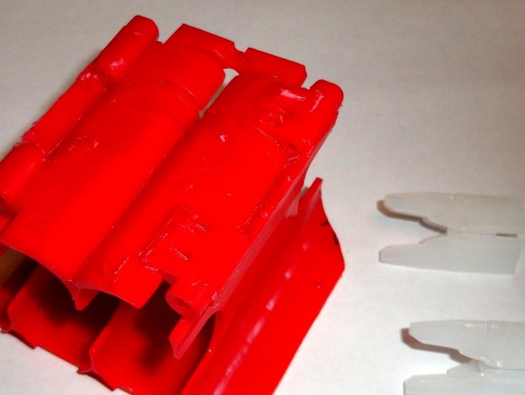
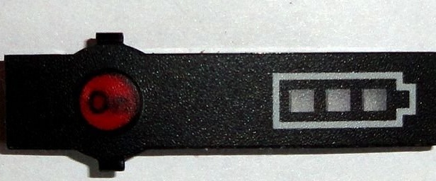
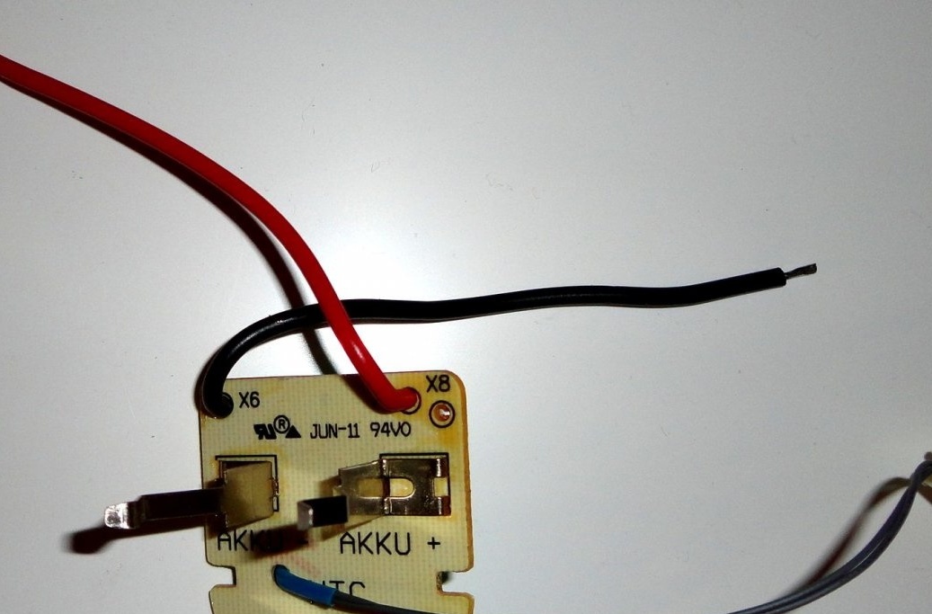
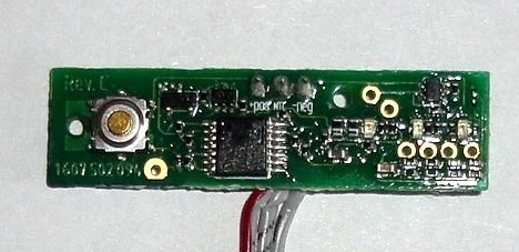
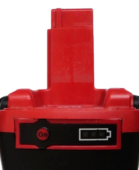
The indicator is used from the "killed" Bosch Li-ion 14.4V battery.
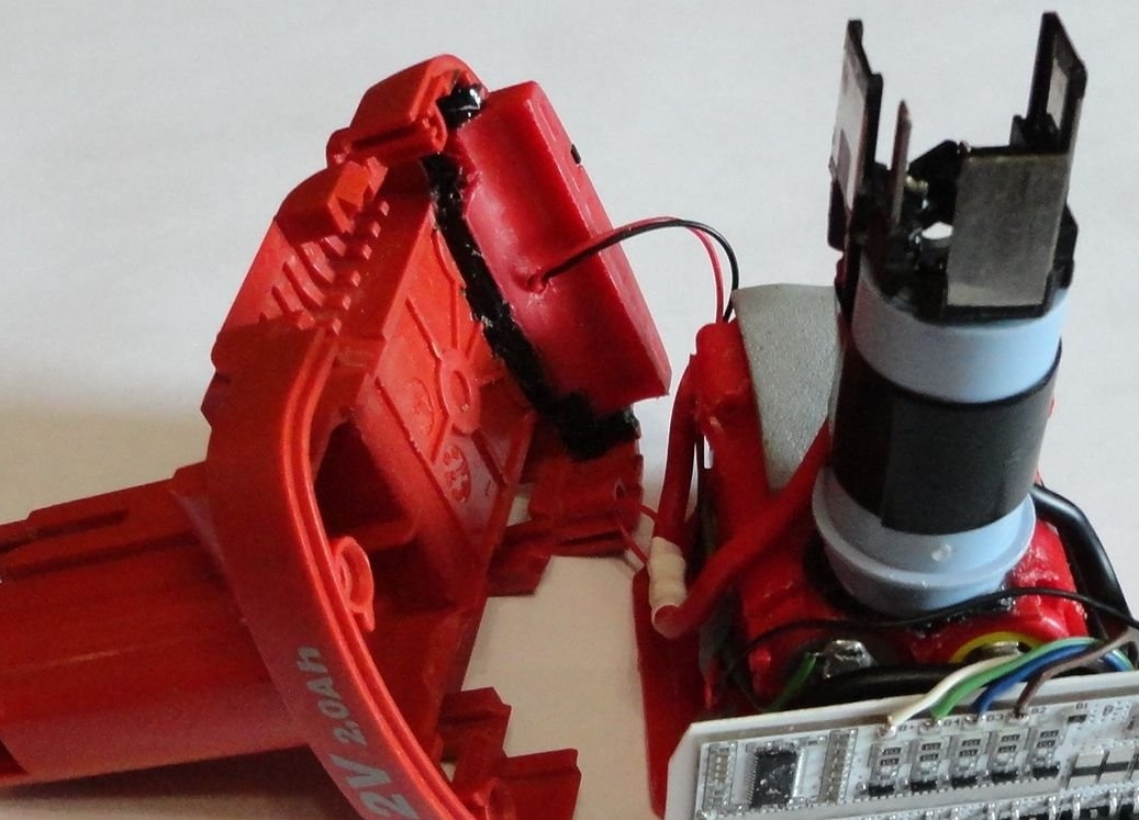
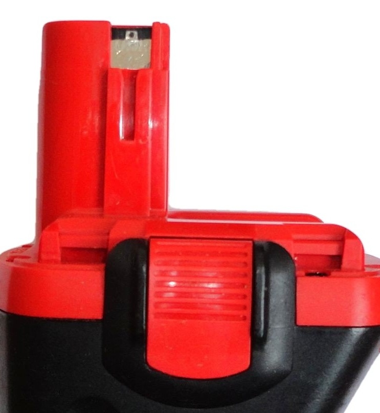
To fix the contact pad, a support plastic tube with a diameter of 19-21 mm is used.

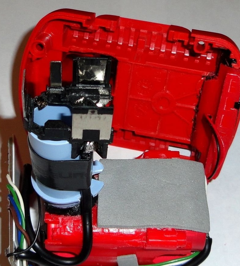
A resistor is bitten out from the contact pad. What prevents the old charger from starting up for Ni-Cd batteries (additional protection against confusion between the batteries and the charger, tested on the Bosch AL1411DV charger). Cuttings for a fragment with indicator fixture are made in the upper and lower parts of the body. This fragment is attached to the upper part of the case with the help of two screws with a diameter of 3 mm and is leveled using hot-melt adhesive. Also, these same screws fix the front panel of the indicator.
Then, using a hot-melt adhesive, the support tube is attached to the upper part of the battery holder housing. The batteries in the holder are fixed in the factory, i.e. using plastic wedges. The contact area with soldered wires is fixed to the support tube with electrical tape. Because at the time of assembly of this battery, I did not have flat conductors, the wiring of the batteries was done by a mounting wire with a 2mm conductor cross section. Between the battery pack and the BMS board there is an insulating plastic gasket about 0.5 mm thick, with cutouts for the wires. To better fix the structure in the case, self-adhesive shock-absorbing pads (used for furniture legs) and two pieces of foamed polyethylene were used. Information stickers are made in the same way as on the memory (see photo).
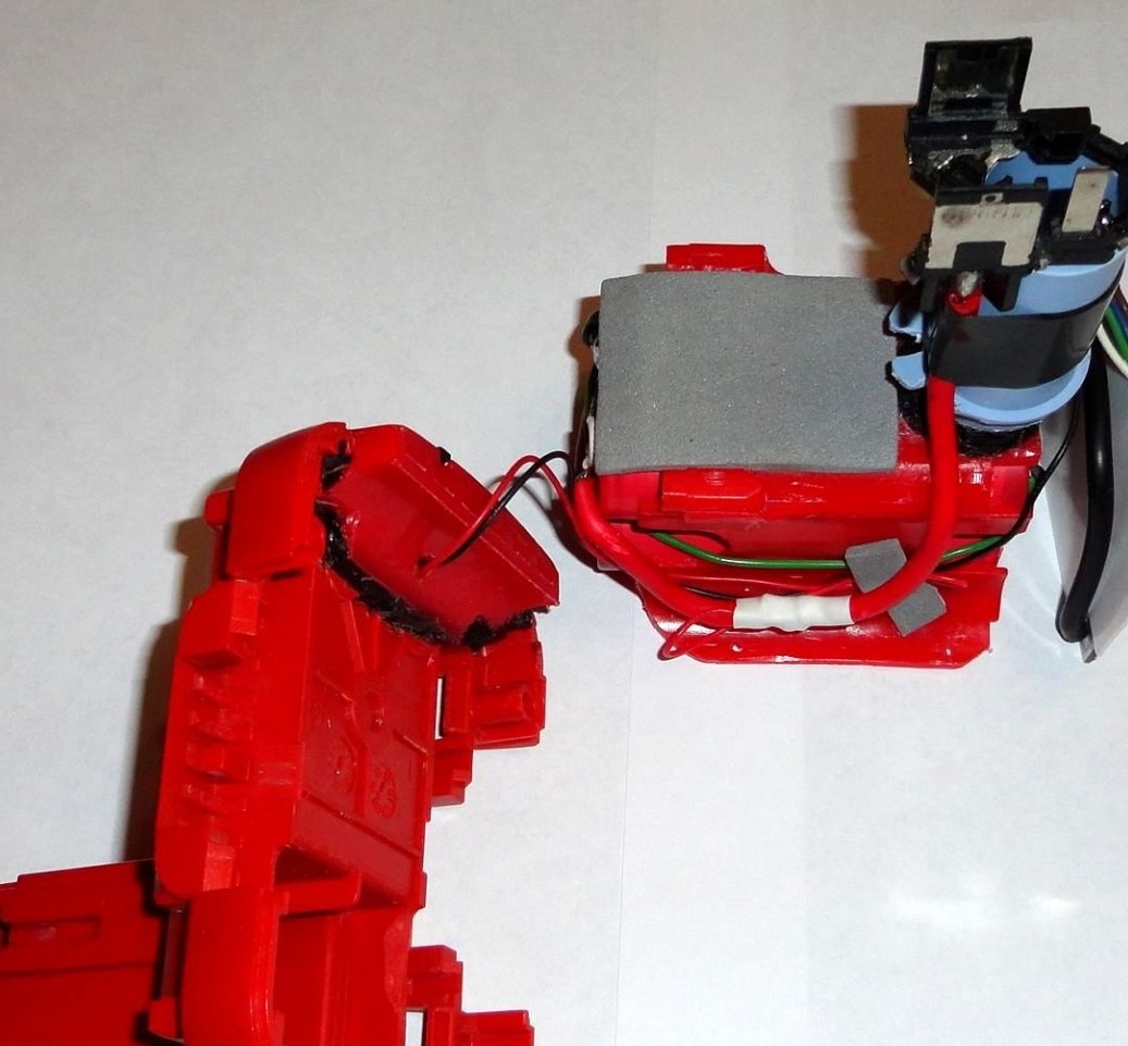
The final result, after the final assembly (see photo).


The entire structure was originally assembled and tested "on the table", after the final assembly was re-tested on a grinder and screwdriver. The result more than satisfied me.
The battery ran out before the protection tripped. Charged to full voltage (16.8V) in 2.5 hours. For the sake of interest, I compared the weight of the native Bosch Ni-Cd 14.4V 2.4Ah battery to about 840g. and the weight of this battery is about 360g. that is, the difference is almost 0.5kg. All declared protection options for the BMS board are triggered (only thermal monitoring was not checked, there was no suitable thermistor). The battery practically does not heat up, so most likely I will not do thermal monitoring for now.
When the balancing process ends, the LEDs on the BMS board go out before the charging end LED on the charger lights up. Therefore, while the window for observing the balancing LEDs on the battery did not. This is how you like it.
The indicator on the battery is optional (if there is no special indicator, and less work). Since the turned off charger will accurately show the voltage on the battery.
Photos of Chinese modules are taken from the Internet, the rest are ours. If you need additional information, write to the post office, I will try to be sure to answer. Feedback, suggestions and comments are very welcome.
March 2019