
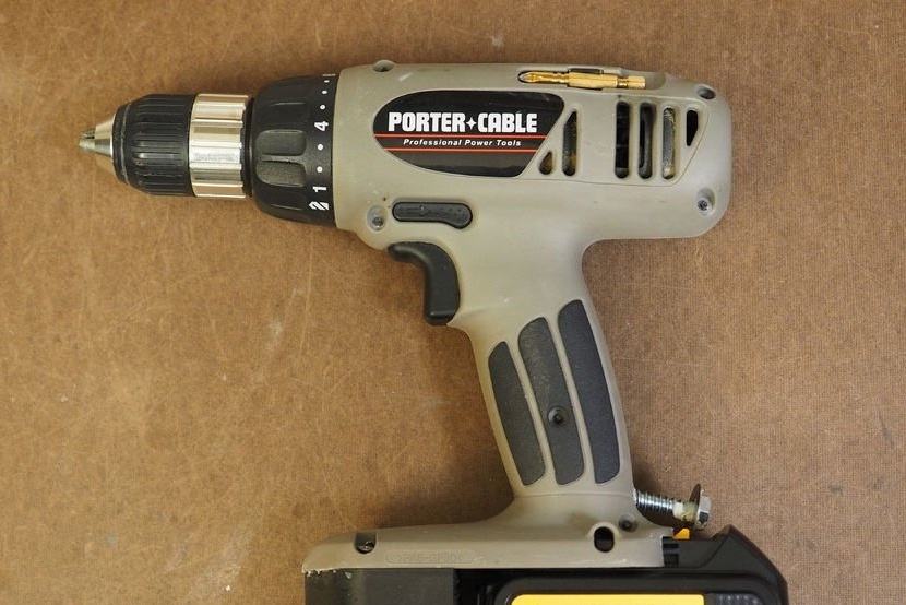
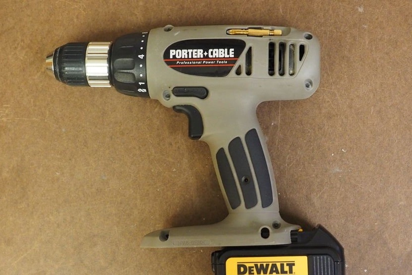
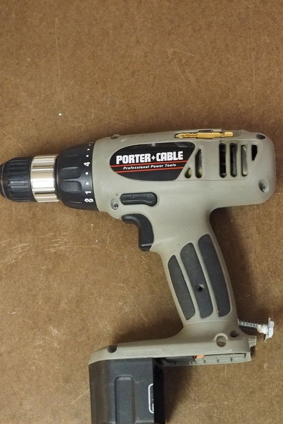
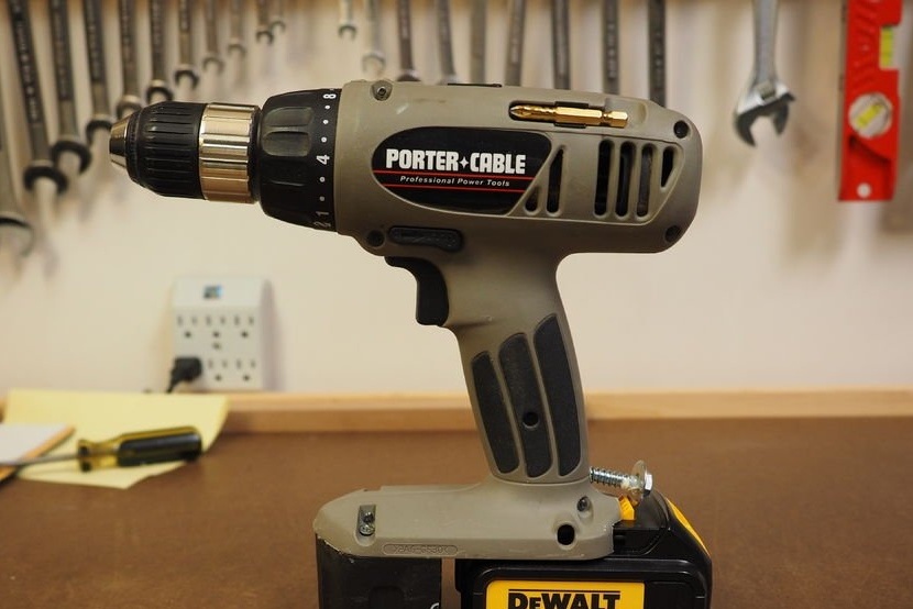
The Porter Cable 19.2V cordless drill was one of the first to truly compete in power and performance. The author of this alteration bought his in 1999 and used it for all types of construction and repair work. Its size and height, combined with excellent balance, make it an excellent tool in tightening screws for decking and even eye bolts without bothering your wrist. However, Porter Cable left the line of screwdrivers in 2002, and it was difficult to find parts.
The author replaced one discharged battery, one half-dead and a charger with a budget DeWalt battery. Despite the fact that the new drill has more power, has half the weight and half the price, its grip is very weak for flooring bolts. Apparently, DeWalt wants you to buy a hammerhead ... Not wanting to spend another $ 90 on a hammerhead that won't stop when the screw is flush, the author decided to bring his old screwdriver back to life.
Like modern tools powered by lithium-ion batteries, Porter-Cable 19.2 V batteries are inserted along the carriage. The author noted that the guides and the position of the DeWalt battery terminals were remarkably similar to the old Porter Cable ... and the polarity was identical.
He decided that this could turn out to be a very simple mod and it should work well.
So, here is a way to resurrect the old Porter Cable instrument 19.2V ...
Step 1: Materials and Tools
Materials:
- One lithium-ion battery Dewalt 20V Max. 3.0 Ah or more is preferred;
- 60x 300mm. delayed screw;
- 60mm. flat washer;
- 6 x 12 mm. flat head screw (2 pcs.);
- ballast weight 120-170 gr. (optionally);
- Construction glue, such as Liquid Nails;
Instruments:
- screwdriver;
- pliers;
- nippers;
- drill;
- A small hacksaw for metal;
- Knife;
- Dremel (optional);
- skin;
Step 2: Loosen the screws
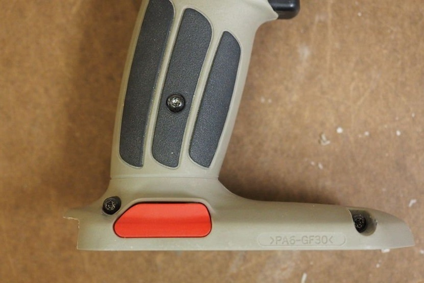
Using a screwdriver, loosen the handle and foot screws about half the length of the screw.
Step 3: Removing the plug and terminal cover
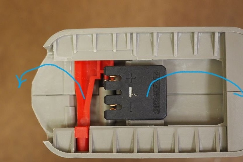
Remove the red battery lock, spring, and black terminal cover. Set aside the terminal cover for later.
Step 4: Release the Guides
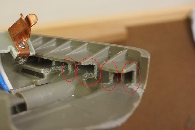

Tighten the screws on the handle again. Each sliding channel on the housing should be approximately 3 mm deep.using a drill to allow the DeWalt battery to slide. The rail should also be a little subtle next to the entry point. Cut the plastic with a saw and a multi-purpose knife or dremel. During operation, frequently check the movement of the battery along the rails to make sure that the movement is not too tight and not too weak.
Step 5: Check Insertion Depth
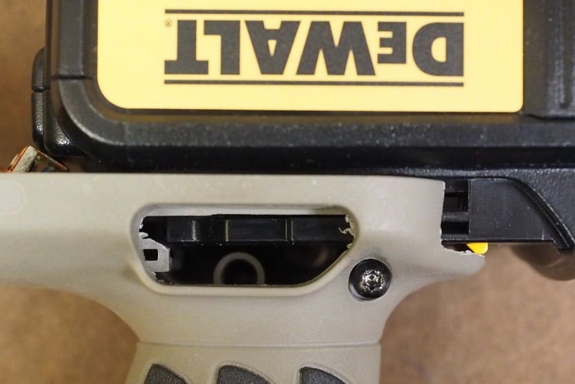
Continue to cut and verify installation until the battery contacts slide forward to the terminal mount and the battery latch snaps into place against the leg.
Step 6: Change Electrical Contacts

Note: this mod is irreversible.
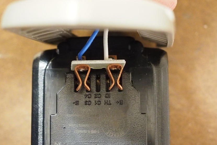
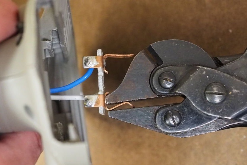
Install the terminal clamp over the DeWalt battery terminals. The external terminals of the clamp must be aligned with the positive and negative terminals of the battery. Internal contacts are redundant and will be cut off.
Then use pliers to straighten each external contact. Work with each contact until it aligns perfectly with the clip inside the DeWalt battery.
Be careful not to short-circuit the contacts with a metal tool!
Step 7: Trimming the terminal cover
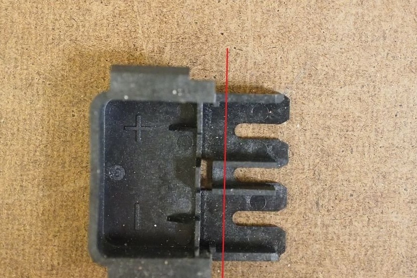
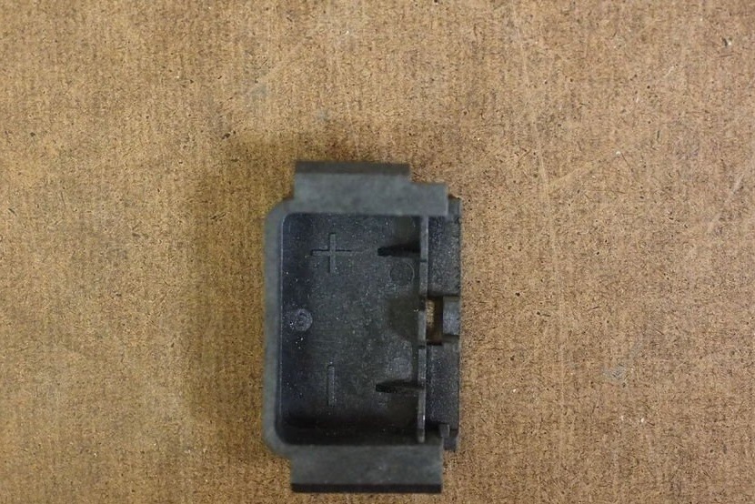
Cut the terminal cover along the red line as shown in the photo.
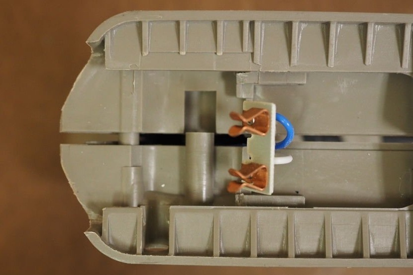
Step 8: Assembling the Electrical Terminal
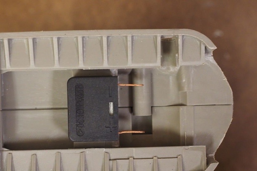
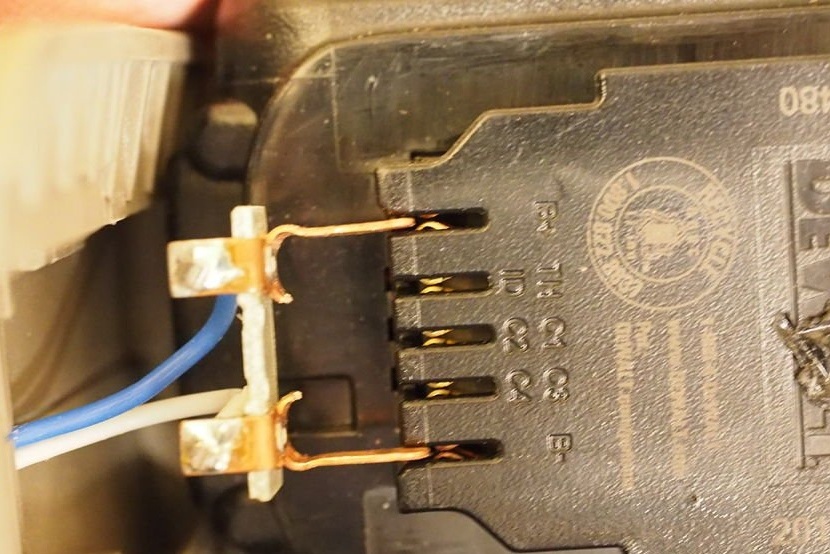
Loosen the handle screws again. Insert a small PCB with copper terminals into the original groove in the holder, then reinsert the holder into the drill. Tighten the screws.
Step 9: Matching Contacts
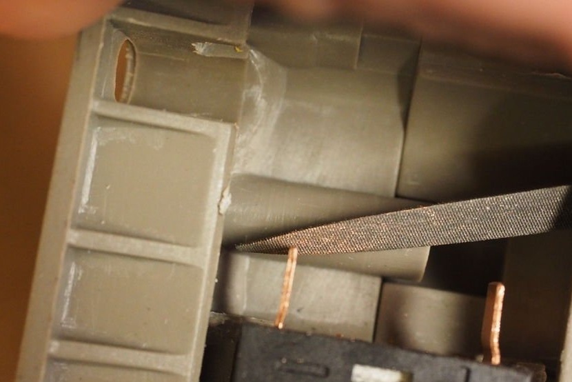
Cut the contacts so that they protrude by 7 mm. for the terminal cover. Use a file to round sharp edges.
Step 10: Battery Installation
Insert the DeWalt battery again, making sure that it does not get pinched or catch and smoothly fit into the contacts.
Step 11: Health Check
The drill has good contact and power. There are a couple of things left to do to make the instrument look finished:
1) Add a latch so that the battery does not fall out
2) Add front support and additional ballast weight.
Let's start with the battery latch ...
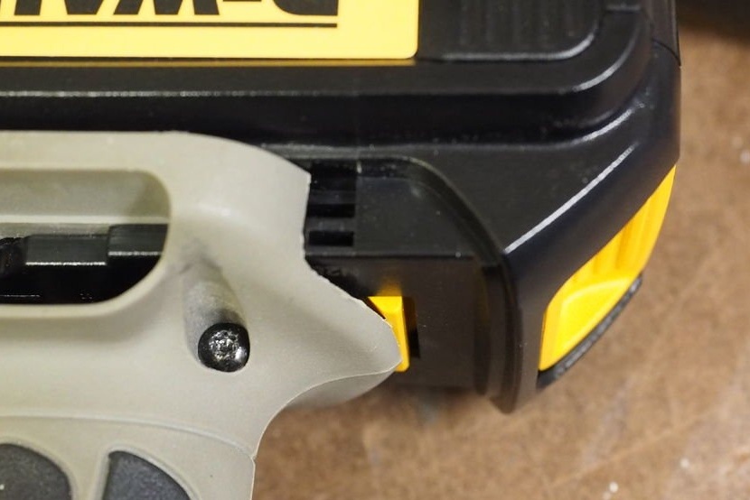
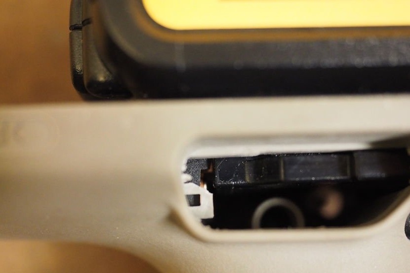
Step 12: Marking and Trimming the Leg
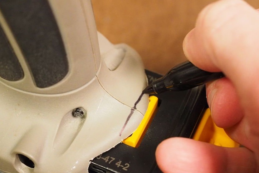
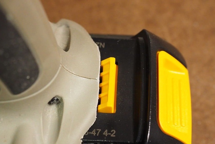
Mark the inside edge of the yellow tab on the battery on the screwdriver body. Cut the plastic with a hand saw. The yellow key should extend fully with the battery inserted.
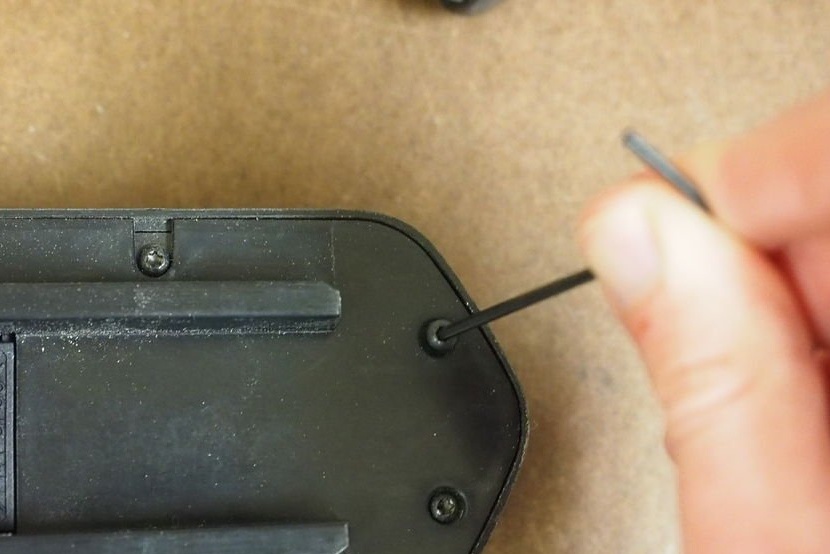
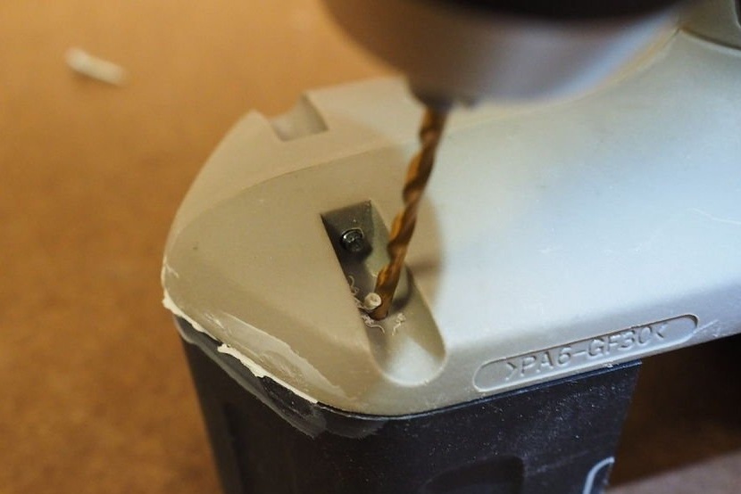
Step 13: Drilling a Hole
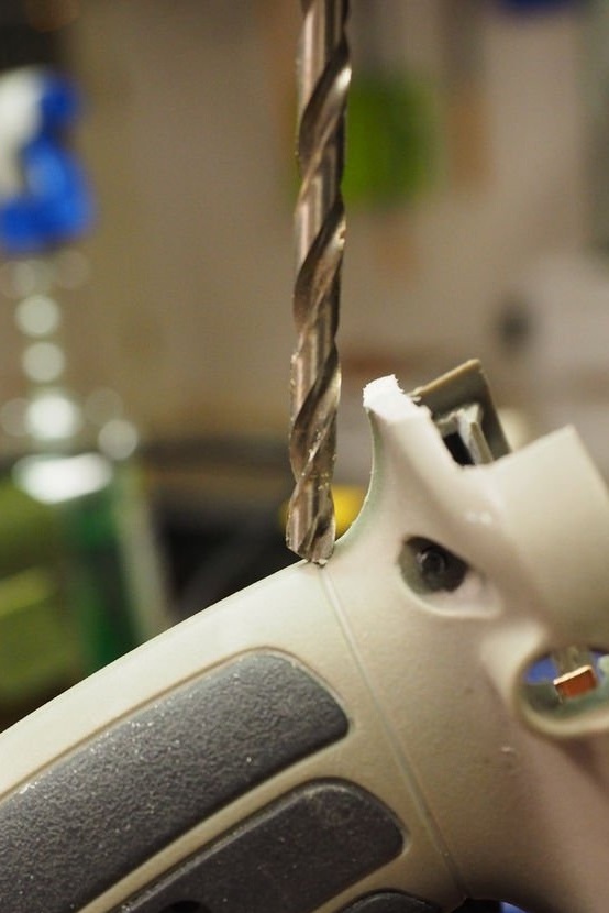
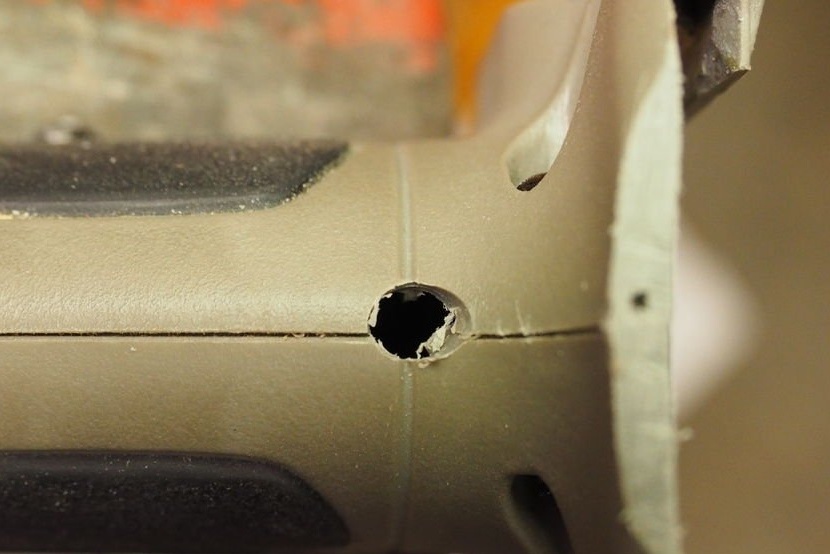
Drill a test hole with a diameter of 5 mm. at the base of the handle as shown. Seams in plastic create a natural starting point. Tilt the drill by 15-20 degrees, as shown in the figure, so that the head of the screw with the delay coincides with the yellow color of the battery.
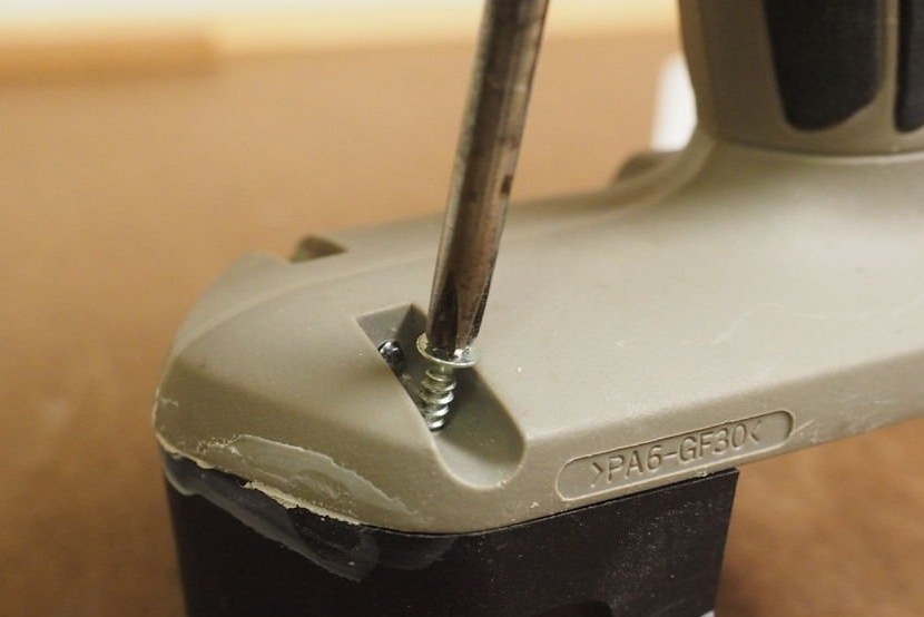
Step 14: Install 6mm. screw
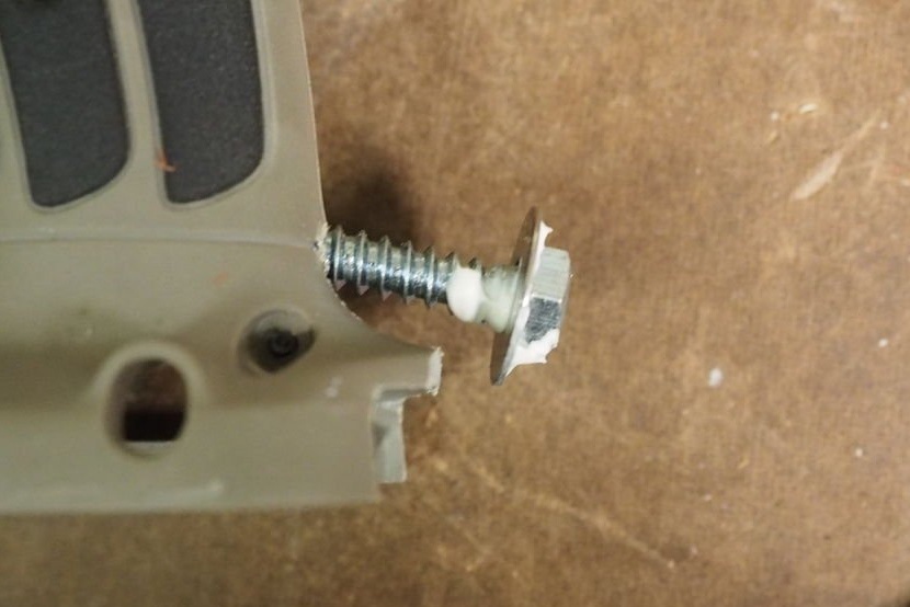
Screw in the fixing screw until a gap of 6 mm appears between the head and the cut-out housing. Check if the battery is installed correctly. If the pointed end of the battery does not have good grip on the head, add a washer. Glue the washer.
Insert the battery and adjust the depth screw until you get a good fit.
Step 15: Front Support: Removing the Battery Screws
These last steps relate to the front support. It is made from a dead Porter Cable battery.
Remove the six screws in the housing with a screwdriver.
Step 16: Removing the Battery
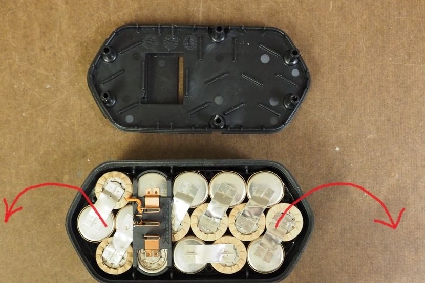
Remove the battery cover and remove the items. Replace the cover and tighten the end screws. Leave the two middle screws outside.
Step 17: Marking the Cutting Location
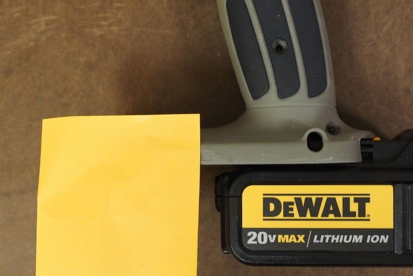
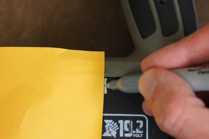
With the DeWalt battery inserted, place the adhesive tape slightly in front of the battery. This will give a mark where the battery case should be cut. Remove the Dewalt battery, insert the empty Porter Cable battery case, and drag the mark.
Step 18: Cutting the Battery

It is necessary to cut the body completely to the mark. Hacksaw for metal gives a good and clean cut. Grind the counterweight if necessary.
Step 19: Optional: Add Ballast
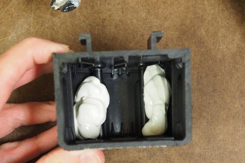
The new battery is lighter than the old, despite the fact that it has a much larger capacity, and sits further on the body of the screwdriver. Adding weight to the front support helps restore the weight and balance of the original tool. As a counterweight, the author added five 19 mm. flat washers. Fix them with construction glue.
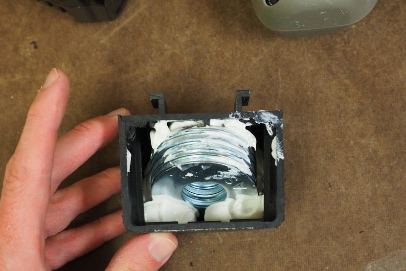
Step 20: Securing the Ballast
With the support in place, drill holes with a drill for two 4 or 6 mm screws. Install the screws.
You can also watch a video of this modification: