» Topics » Advice »Power bank transistors

Power Bank Transistors


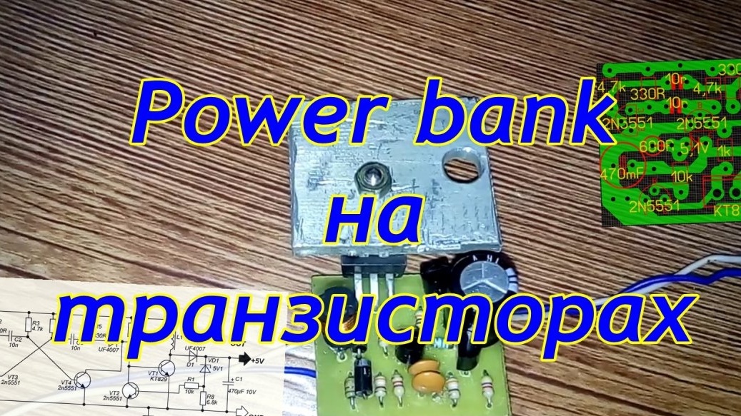
Hello guys) we will collect the bank from the trash can say) these details are in the bins of almost every radio amateur! This scheme from aka kasyana, liked the simplicity. We will repeat and test it)

And here is our scheme

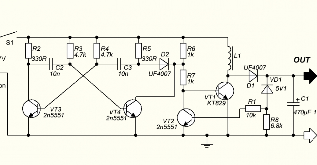
it is made on a multivibrator, transistors can be used at least kt 315. And the power component kt 829. The voltage here is stabilized!
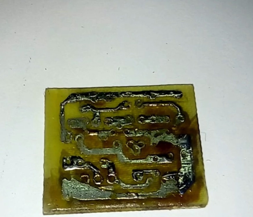
We etch the board

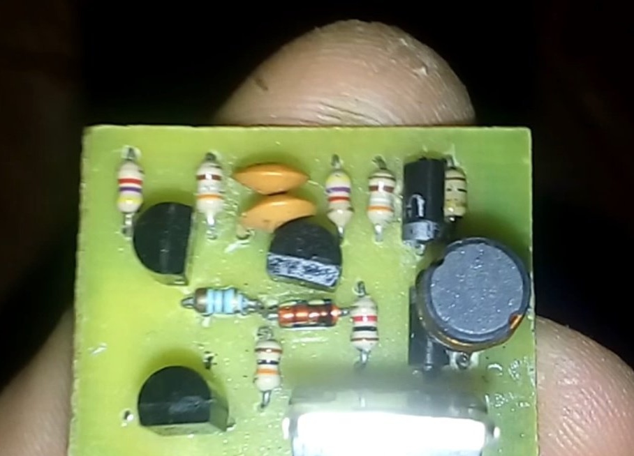
We solder all small radio components, i.e. resistors from the beginning! 2 ceramic capacitors. 3 transistors 2n5551 series
5.1V zener diode, 2 high-speed diodes. Power transistor and throttle wound on a dumbbell. You can also use a powder iron ring! The number of turns 25 with a diameter of 0.5-0.8.

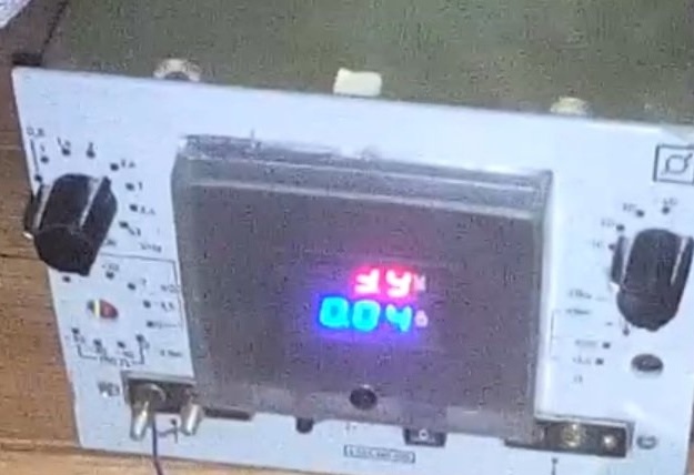
We check its idle current, I got 40-50 mA - this is of course a lot.

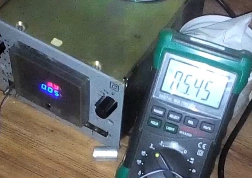
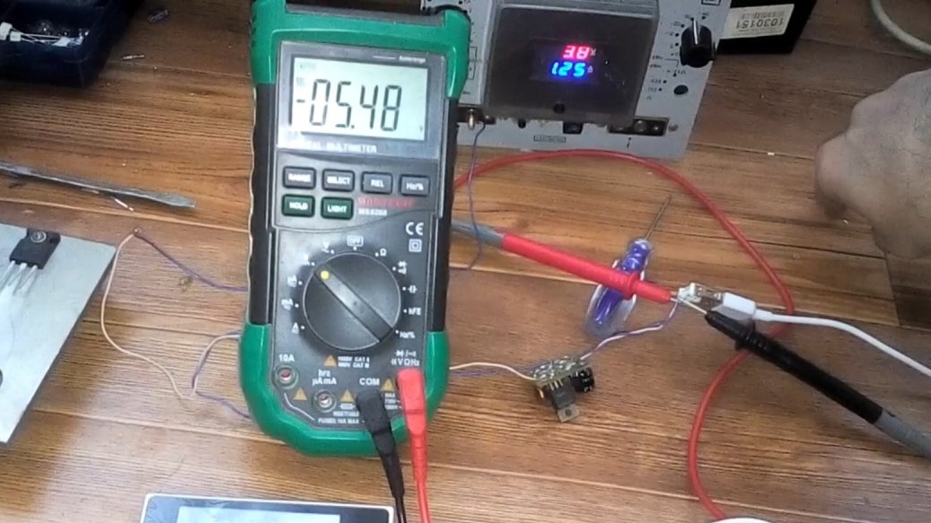
We measure the output voltage, we obtain an output of 5.5 V idling.

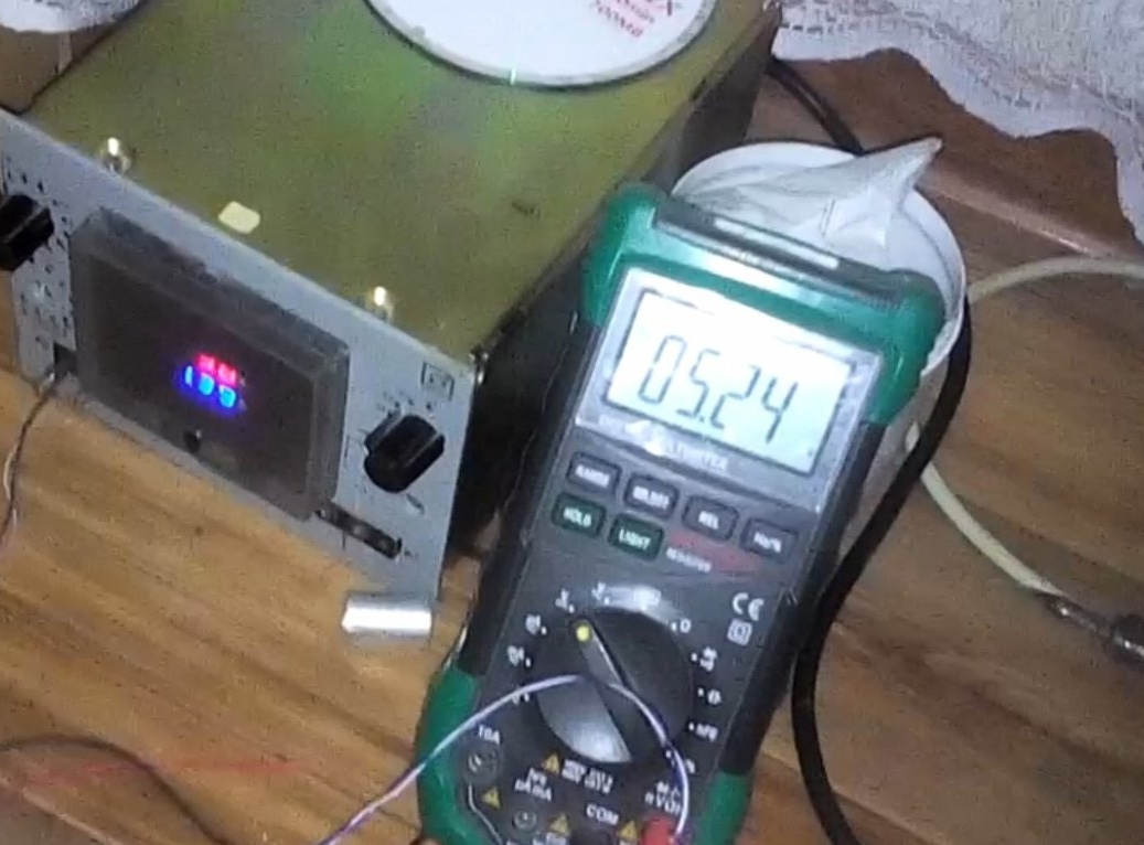
Well, let's torment him with an incandescent lamp, I have it at 24 V, but it doesn’t matter. We look at the voltage drop, and it turns out 250 mV. And the current consumption is almost 1.5A.

And finally, let's try to connect to the phone! And as we see the phone began to charge)

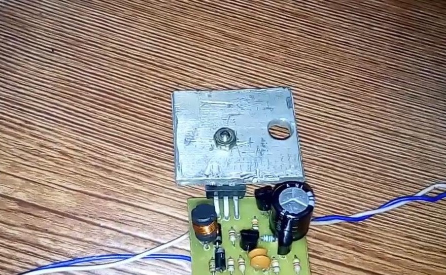
At the same time, there is a noticeable heating of the power transistor, so it needs to be planted on a radiator in the form of an aluminum plate. In the future, insert it into some sort of building, bring it to mind!


Link to the archive with the printed circuit board

Suitable for topic

Related topics

Add a comment

    • smilesmilesxaxaokdontknowyahoonea
      bossscratchfoolyesyes-yesaggressivesecret
      sorrydancedance2dance3pardonhelpdrinks
      stopfriendsgoodgoodgoodwhistleswoontongue
      smokeclappingcraydeclarederisivedon-t_mentiondownload
      heatirefullaugh1mdameetingmoskingnegative
      not_ipopcornpunishreadscarescaressearch
      tauntthank_youthisto_clueumnikacuteagree
      badbeeeblack_eyeblum3blushboastboredom
      censoredpleasantrysecret2threatenvictoryyusun_bespectacled
      shokrespektlolprevedwelcomekrutoyya_za
      ya_dobryihelperne_huliganne_othodifludbanclose
8 comments
Guest Sergey
It was possible to not charge the board, cut the paths with a cutter and gently solder, so as not to fill the track with solder. The more foil (earth) left on the board, the better, especially for RF circuits. Moreover, there is a problem for beginner radio amateurs, they overheat the narrow small contact pads with a soldering iron and they move away from the board.
Guest Sergey
The circuit is assembled on a single transistor KT-805, coils 10 and 5 turns of 0.5 mm wire per fer. ring with a diameter of 16-20 mm, 1 resistor -100 ohm, one diode, one zener diode 5.1v or 5.6v, 1 el.cond. 100-470 microfarads Power 1, 5 volts. Yield 5.1 or 5.6 volts.
Guest Sergey
AleX, you can buy everything except brains))) So you have nothing to do here.
Guest Alex
You can already buy a ready-made bank from the Chinese. And rename this site "UAEExpress"
RUVictor
Converter voltage module USB to Ali input 1-5 to 5V output. max current 1.5 a. quiescent current 130 μA price 21 r 01 kopecks.
And it was worth making a garden to make such a stove
Guest Petrovich
If it’s “Verbank”, then rename the site as a handmaker: - /
Guest Grandfather
But in Russian to write the name and purpose of the mind scheme was not enough?
1. It is bad that there is no shutdown on the minimum battery voltage. ((
2. It is better to take a zener diode at 4.7 V.

latest comments

All comments

We advise you to read:

Hand it for the smartphone ...