In this article, the Wizard will tell us how to independently make an LED lamp with a motion sensor and powered by a solar panel.
The big advantage of this lamp is the combination of the two most efficient and greenest technologies: LED and solar. The solar panel accumulates solar energy in the daytime and charges the lithium-ion battery for later use at night.
The range of the sensor is 2-5 meters with a viewing angle of 120 °. When the motion sensor is activated, the lamp lights up for 25 seconds.
Tools and materials:
-Cardboard;
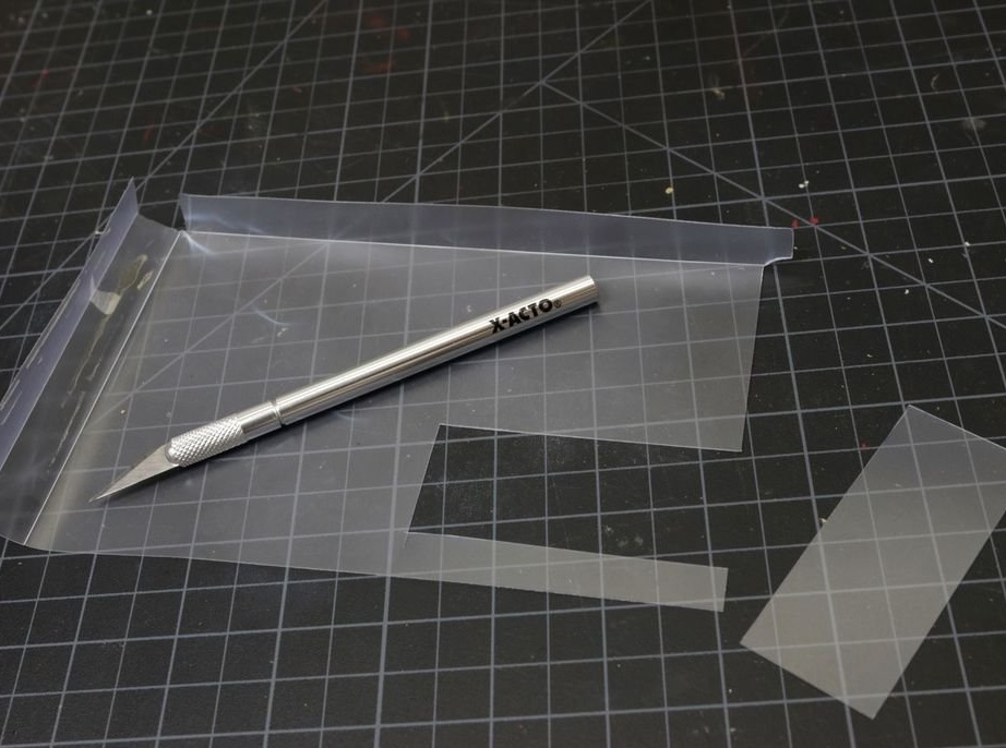
-Matte acrylic;
- controller board;
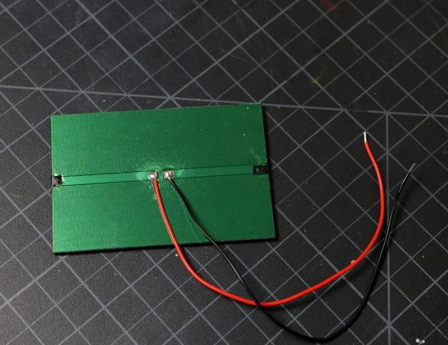
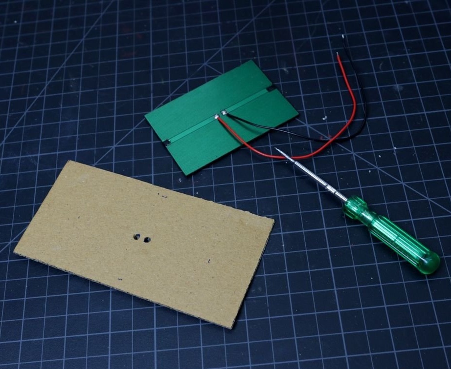
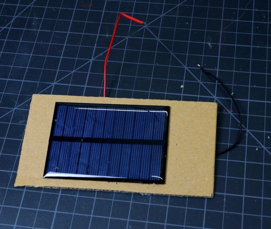
-The solar panel;
-Battery 18650;
-Battery holder;
-LEDs;
-Bread board;
-Wire;
-Heat-shrink tubing;
-Glue gun;
-Soldering accessories;
-Hair dryer;
-Nippers;
-Stripper;
-Knife;
-Screwdriver;
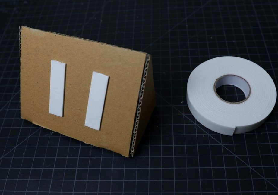
-Double sided tape;
Step One: Scheme
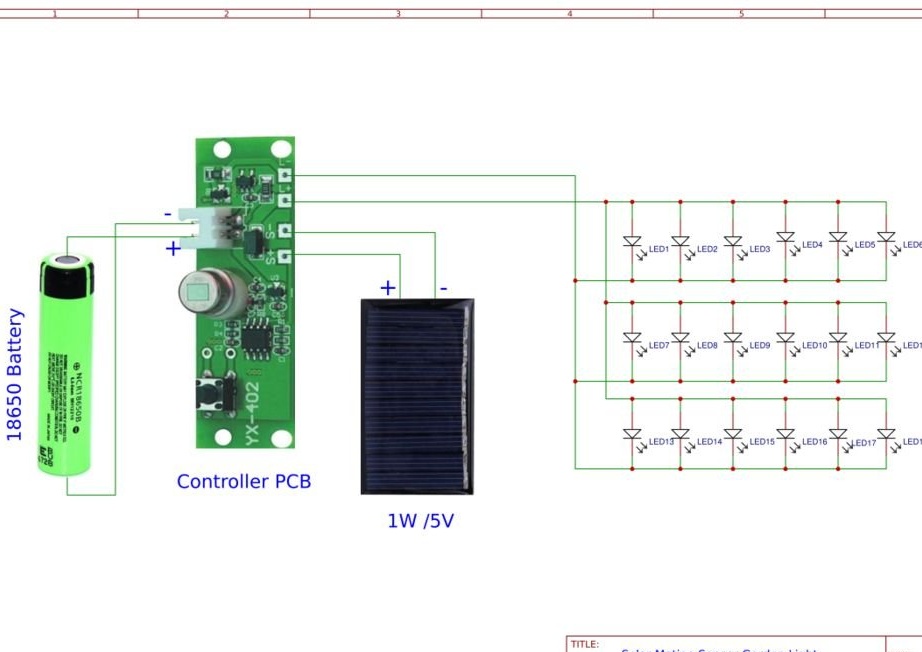
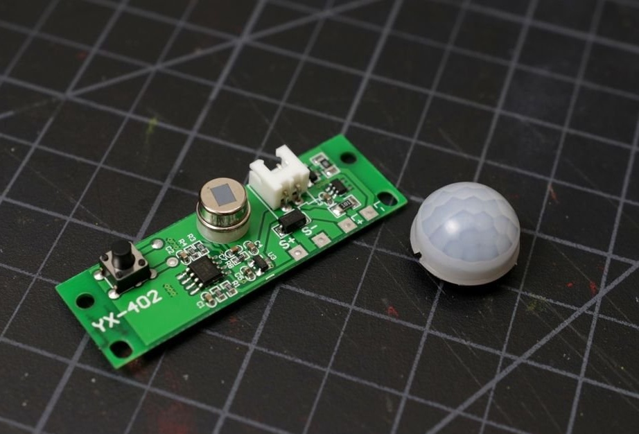
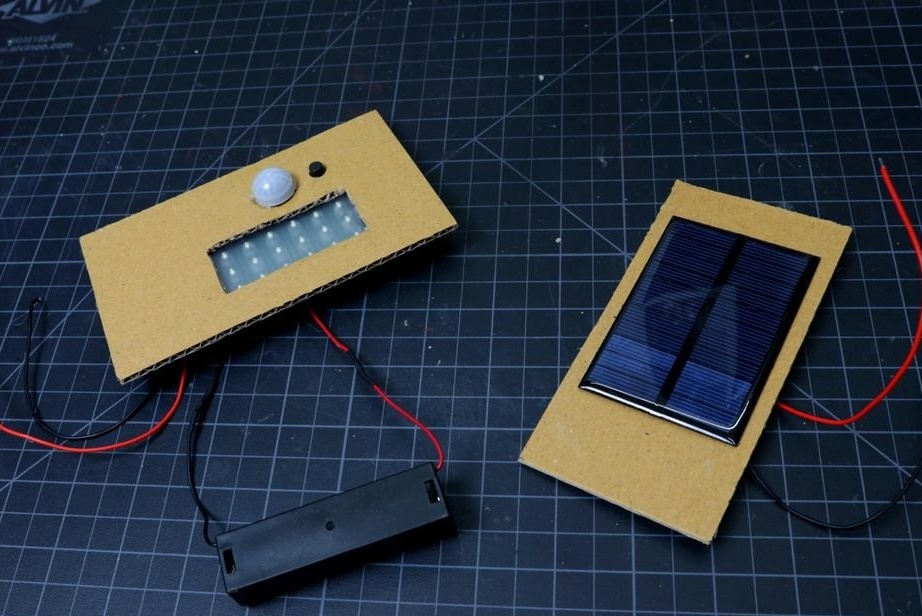
The circuit diagram is very simple. The heart of the circuit is a controller board with a motion sensor.
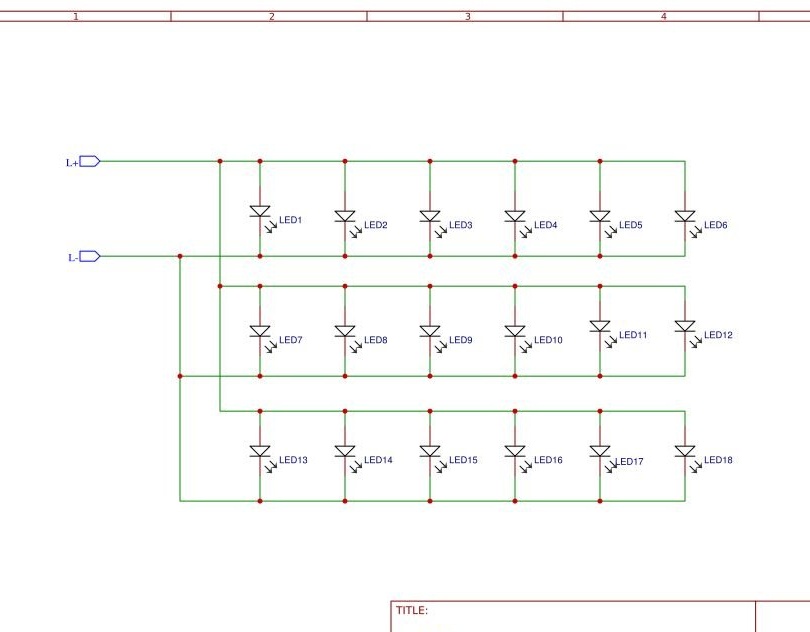
In the daytime, the solar panel collects solar energy from the Sun and accumulates it in a lithium-ion battery for later use at night. The built-in motion sensor is activated only when motion is detected and gives a signal to turn on the LED panel. The LED panel consists of 18 LEDs connected in parallel.
Step two: assembly of the LED panel
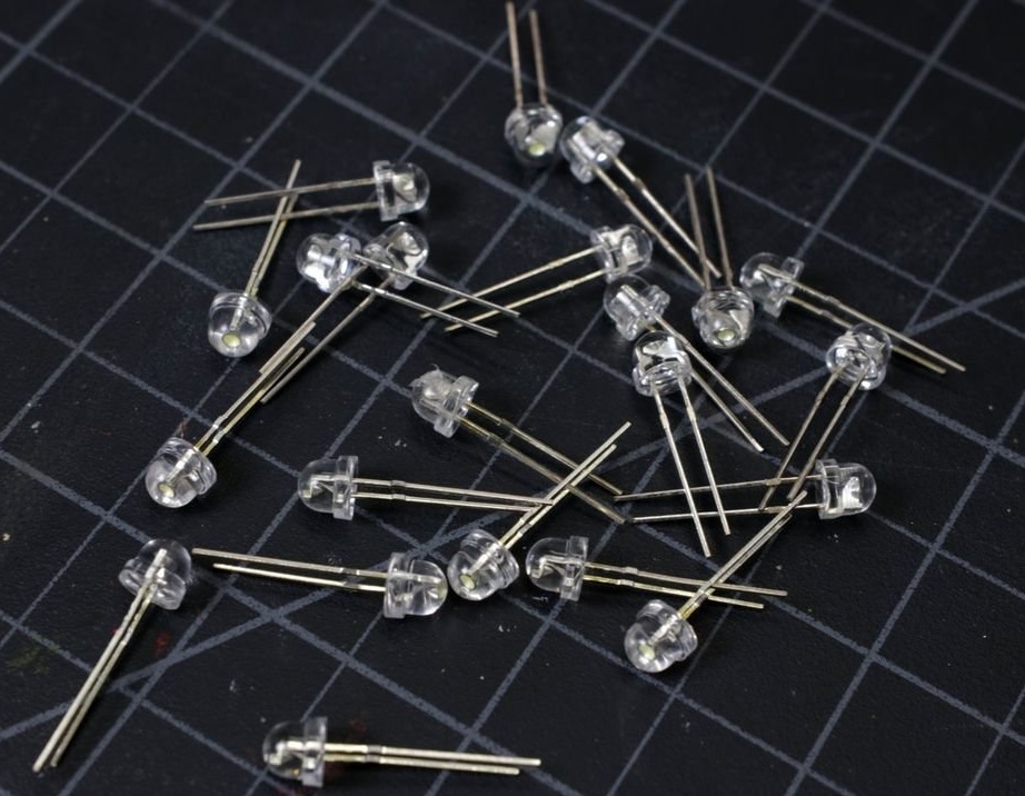
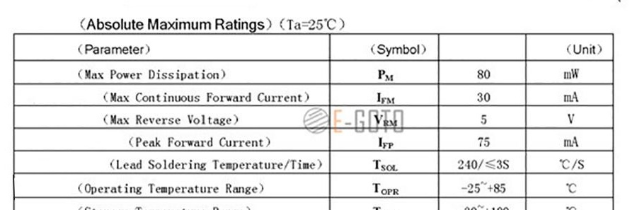
The LED used to make the LED panel has the following specifications:
LED - 5 mm cool white
Voltage - 3.0 - 3.2 V
Current - 30 mA
Power - 80 mW
Luminous intensity - 12000-14000 mcd at 20 mA
Scattering angle - 30 degrees
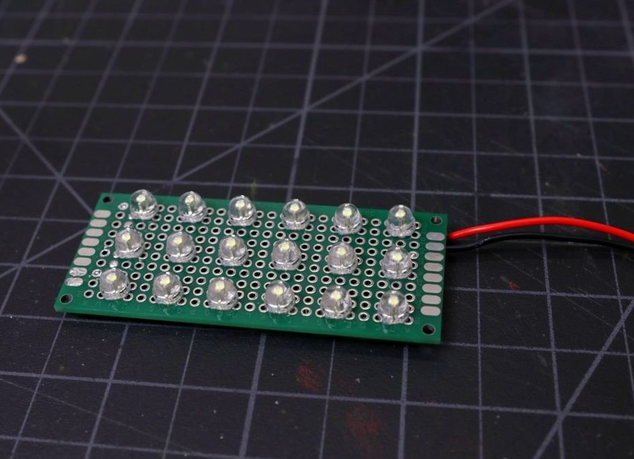
The LED panel uses 18 LEDs.
Maximum power consumption = 18 x 80 mW = 1440 mW = 1.44 W
Luminous intensity per LED = 13000 mcd at a viewing angle of 30 degrees
Lumens per LED = 10.94 lm
Master used this calculator to convert mcd to lumens.
The total lumen reading = 18 x 10.94 = 196.92 lm.Given 25% loss = 147.69 lm.

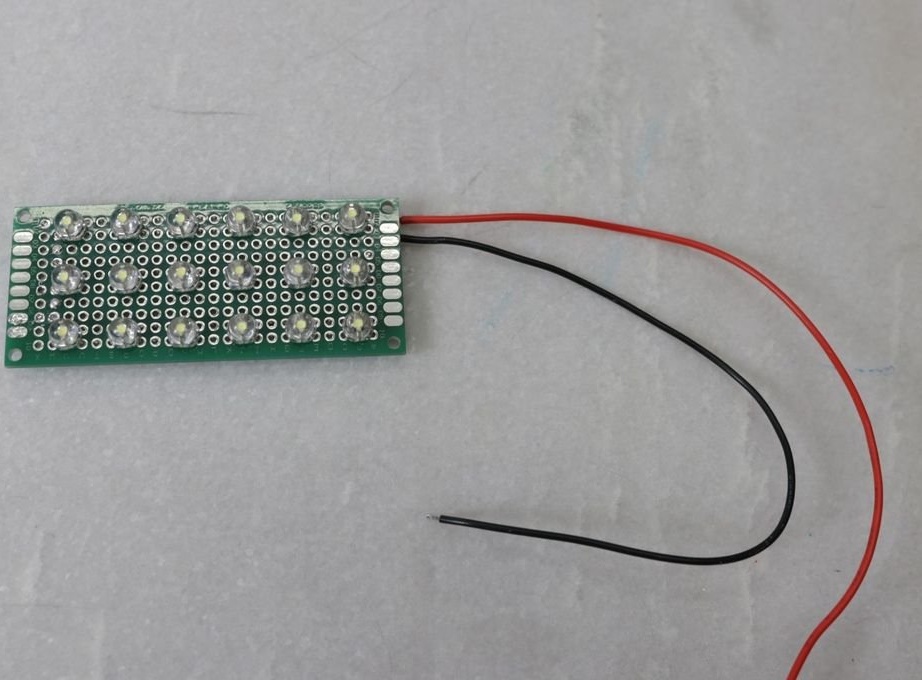
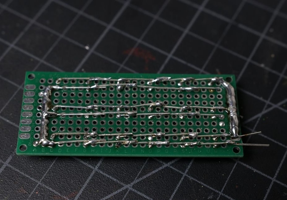
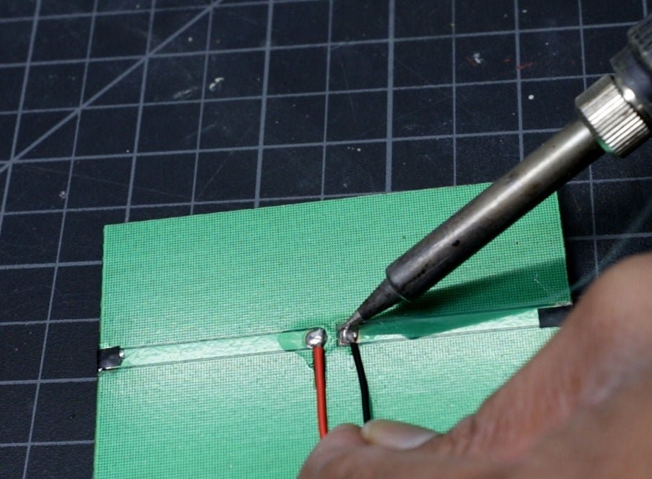
The master collects the LED panel, solders the wires to the terminals.


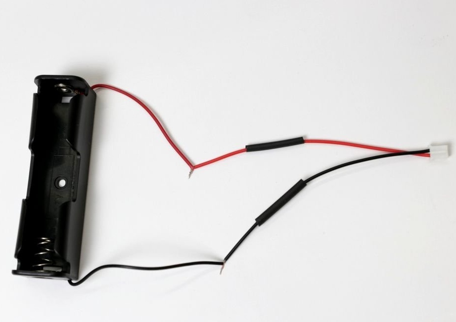
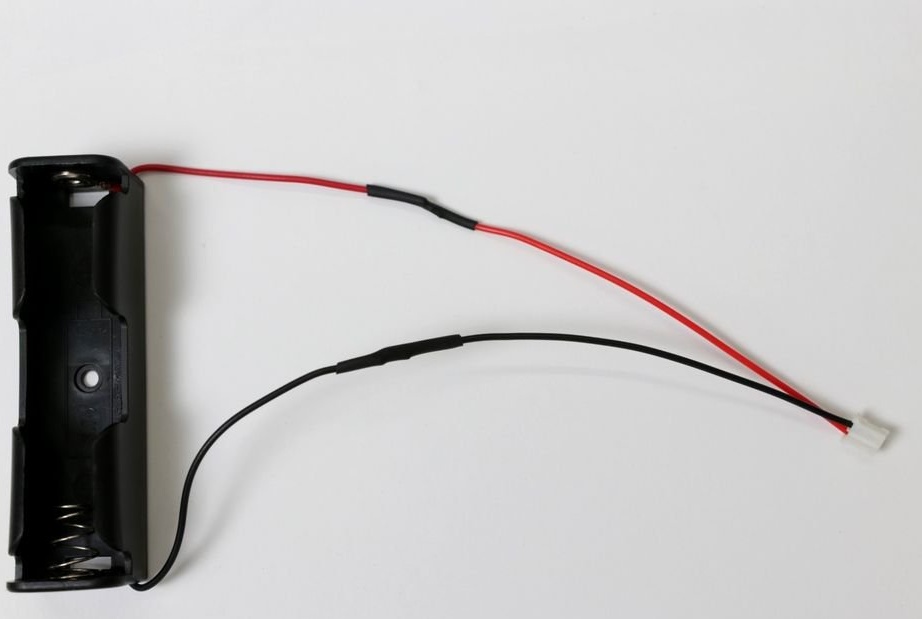
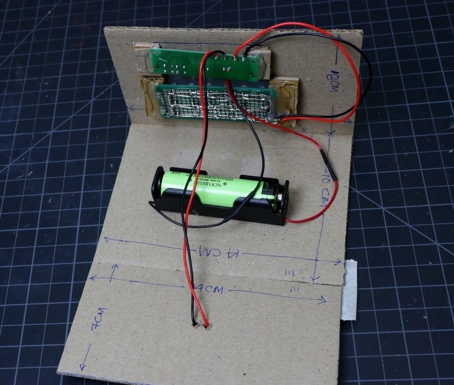
Step Three: Battery Compartment
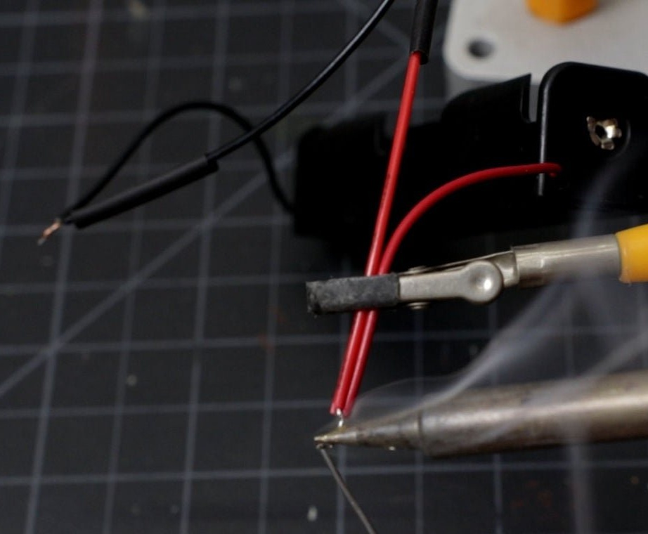
The master connects wires with a connector for connecting to the board to the contacts of the battery compartment.

Step Four: LED Panel
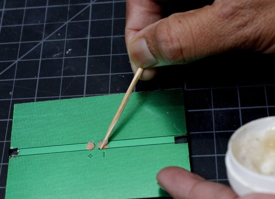
The LED panel has two pads. The master solders wires to them.

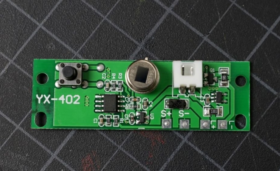
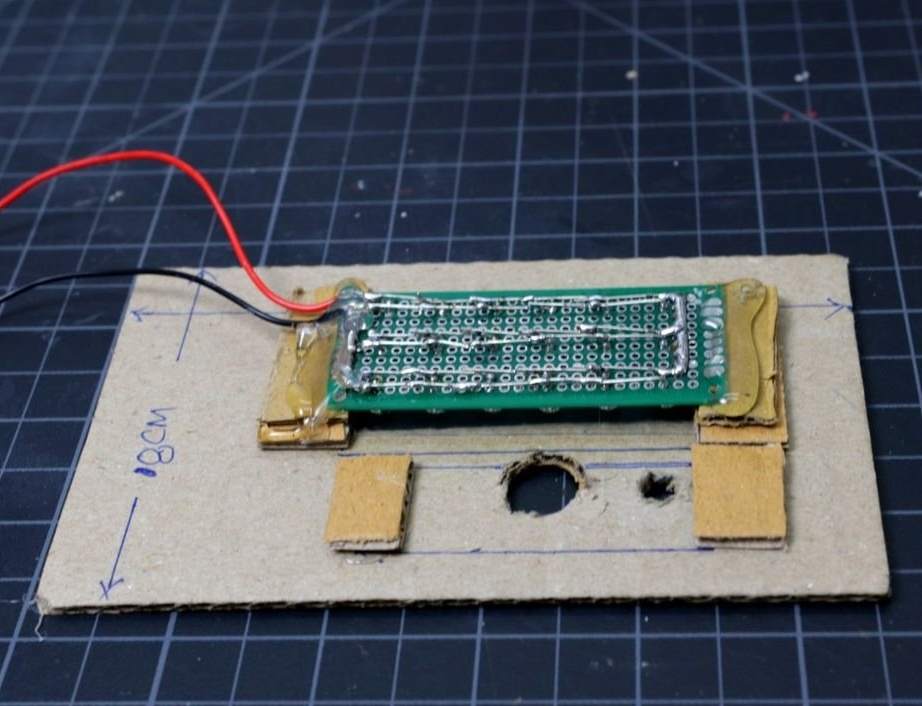
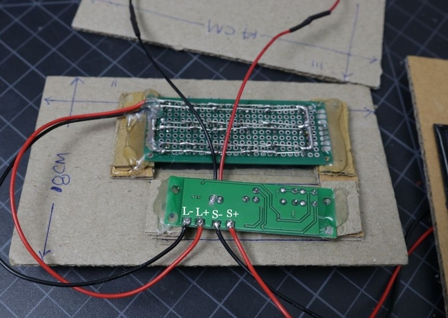
Step Five: Controller Board
The controller board has a motion sensor. The solar panel is connected to the S + and S- connectors, the LEDs to L + and L-, and the battery is connected via the JST connector.
There are 3 different modes for lighting, they can be changed using the button.
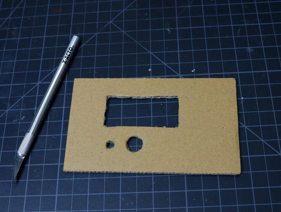
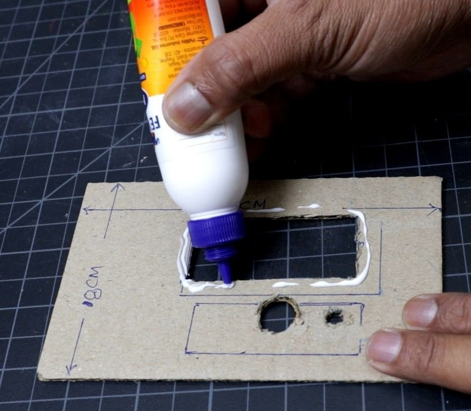
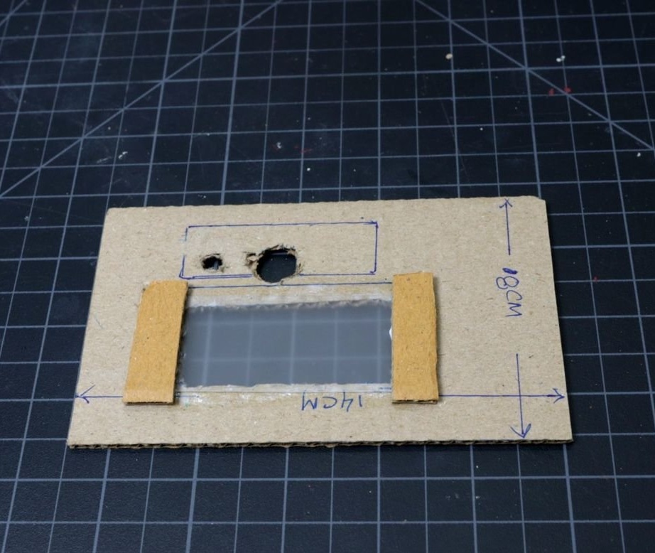
Step Six: The Case
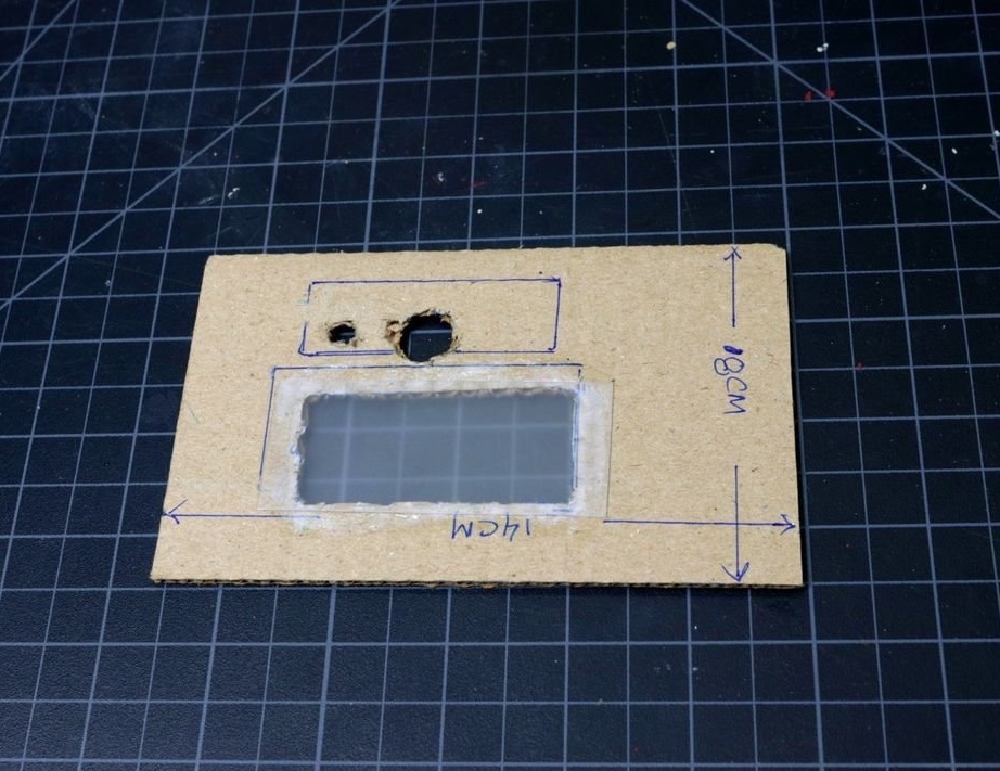
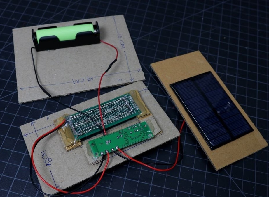
The body was made by a master from cardboard. Cut cardboard in the following sizes:
The back wall is rectangular - 14 x 7 cm.
The front wall is rectangular - 14 x 8 cm.
Upper wall - rectangular - 14 x 7 cm
Two side panels - triangular - 11 x 8.5 x 7 cm
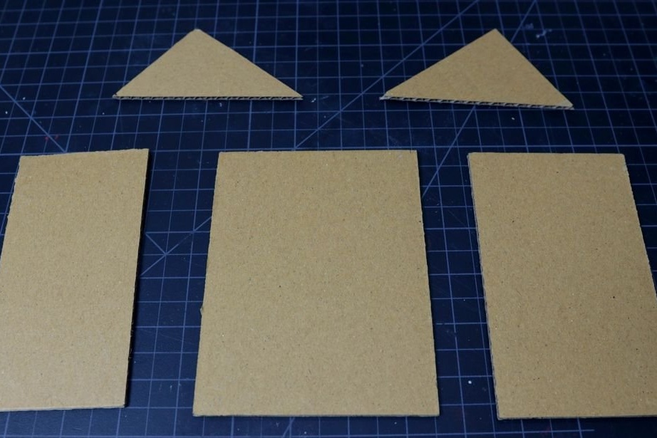
A 3.5 x 7 cm light diffuser is cut from acrylic.
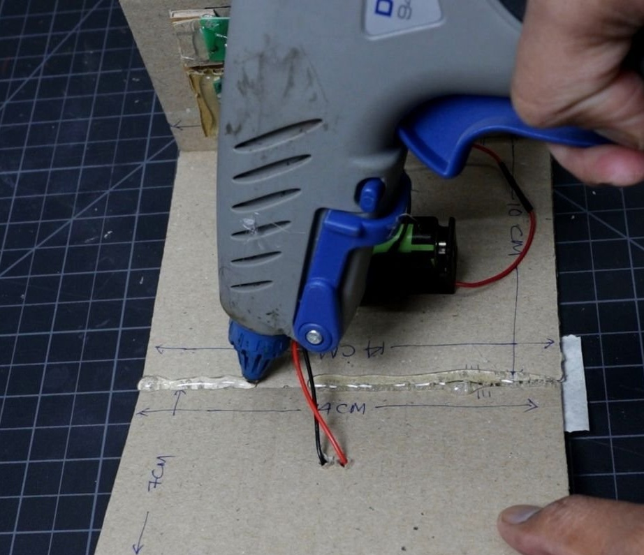
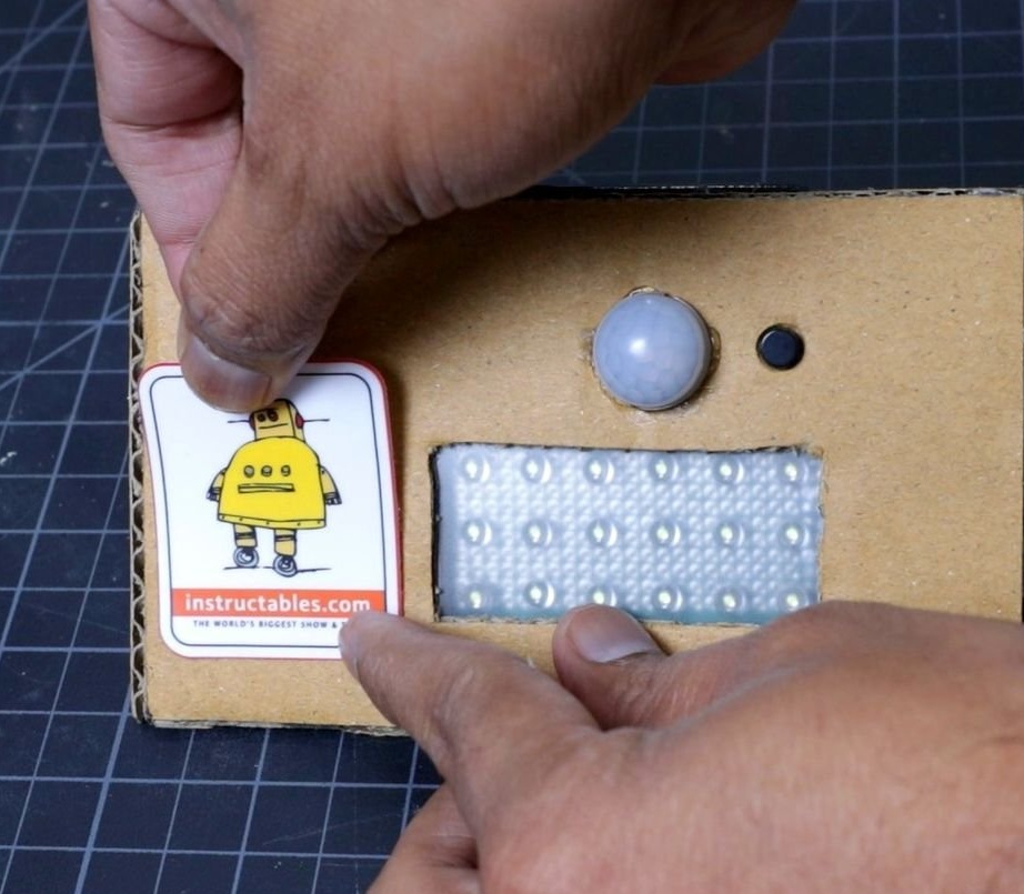
Seventh step: assembly
Now everything is ready for assembly. The master glues the diffuser and LED panel. Secures the controller, LED panel and battery compartment.
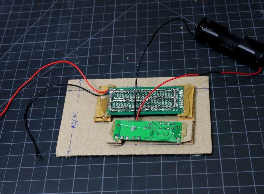
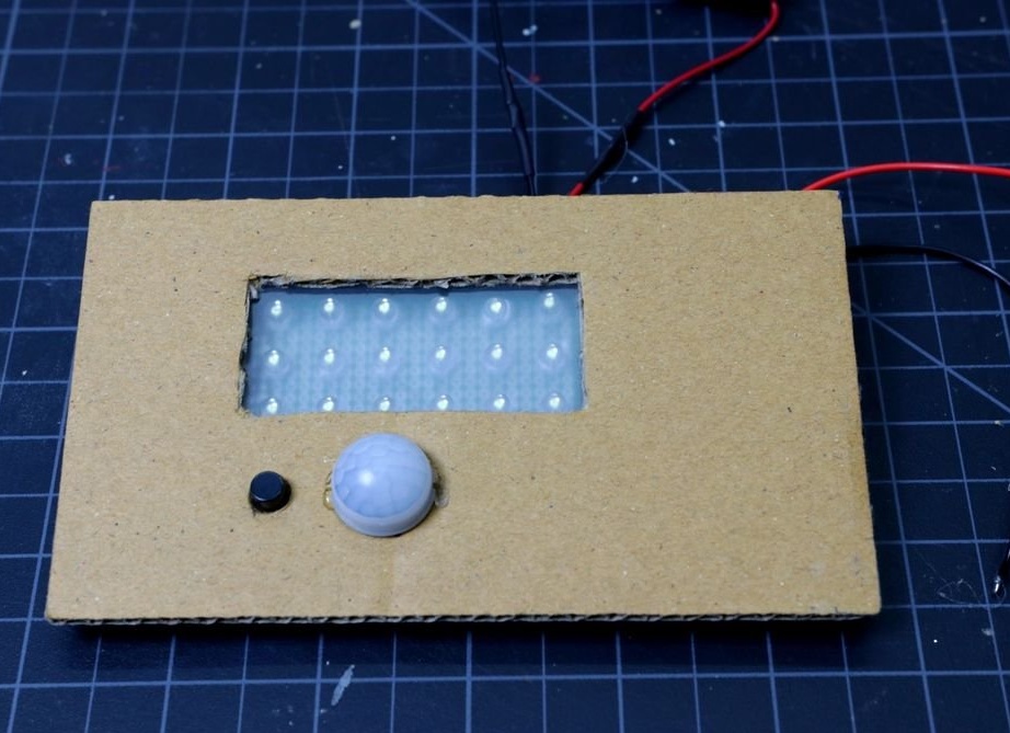


Assembles the body.

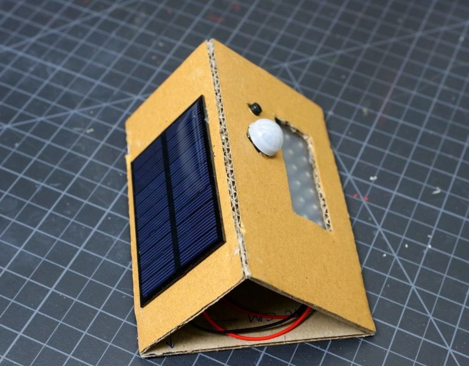

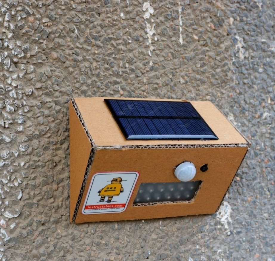
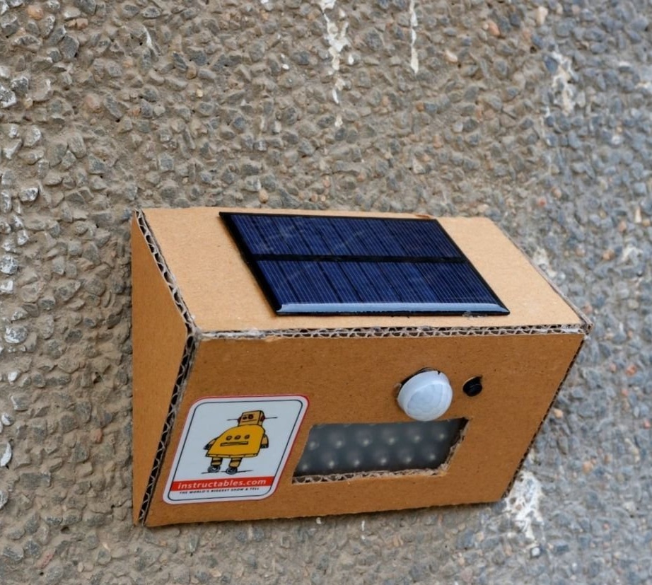
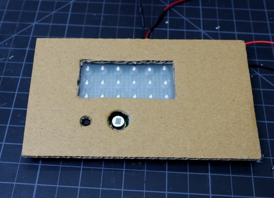
The LED lamp is ready and the master checks its operation.
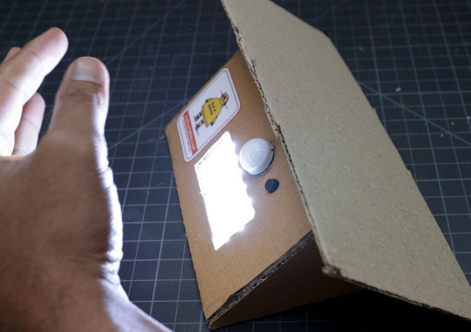

Everything works and now it remains to fix the lamp on the wall using double-sided tape.