Many people like to use cameras mounted on smartphones. I also became the owner of the smartphone and tried its photographic capabilities. It turned out that the quality of photos and the convenience of working just like a camera does not provide a smartphone. And I remembered the camera - the battery eater.
It is no secret that a significant drawback of cameras powered by batteries or AA batteries is the small number of frames made on one set of batteries. The use of AA batteries does not save the situation, good batteries are difficult to maintain, expensive and short-lived. Cameras powered by Li-ion batteries are much more attractive in terms of the number of frames taken per battery charge, but they are also much more expensive. It turned out that this problem can be solved quickly and cheaply, while the disadvantage of Li-ion batteries - the inability to work at low temperatures - can be offset.
To make a mobile camera power system you will need:
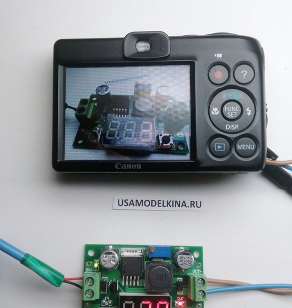
Photo 1
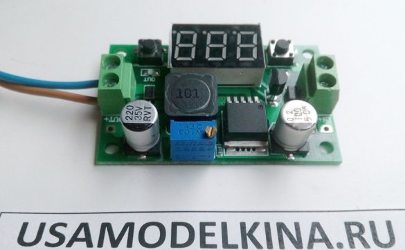
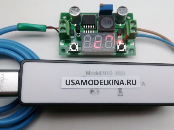
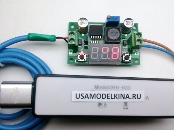
Pulse DC-DC step-down converter with the ability to adjust the output voltage and the current limiting function on the LM2596S-ADJ chip with an LED voltmeter on the board, with an input voltage range from 4 to 40V, with an adjustable output voltage range of 1.5-35V, with a rated current 2A.
Photo 2
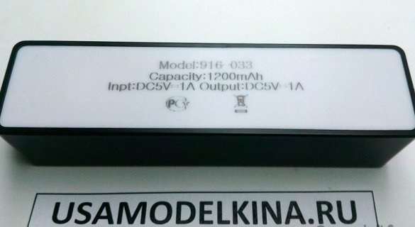
Power bank is a device with a 1200 mAh Li-ion battery with an output voltage of 5 V, with a charge and voltage control board.
Photo 3
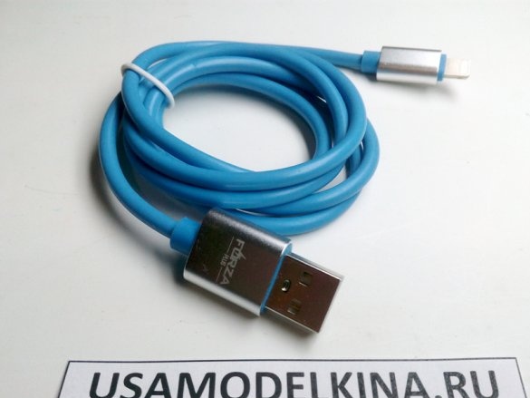
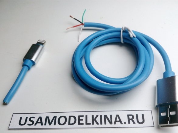
USB cable
Photo 4
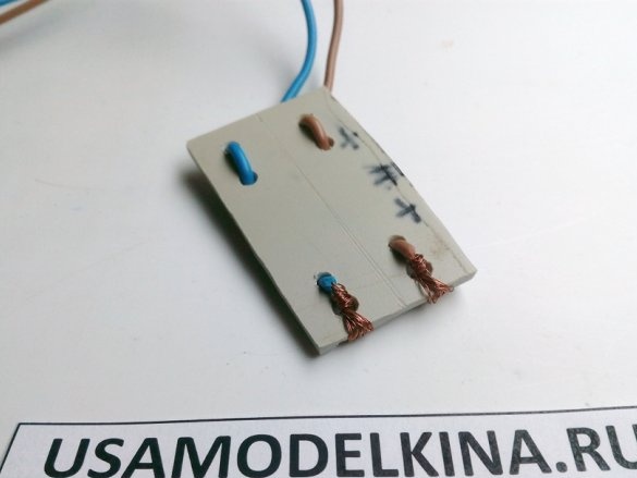
A plate of dielectric material with wires for connecting an adjustable step-down power supply module to the camera's battery compartment. Homemade record. It is installed in the camera compartment for AA batteries.
My camera does not have a connector for connecting an external power supply, so I had to "fence the garden."
Knife.
Screwdriver for precision work.
For this homemade I didn’t even need a soldering iron.
Photo 5
First of all, I cut off the unnecessary USB cable connector, removed the protective cover of the USB cable and stripped the red and black wires. I didn’t even have to check on which wires the power is supplied, since in all USB cables from the power source, plus a constant voltage is supplied through the red wire, and minus a constant voltage through the black wire. In my case, the power bank will be the power source.
Photo 6
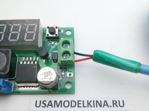
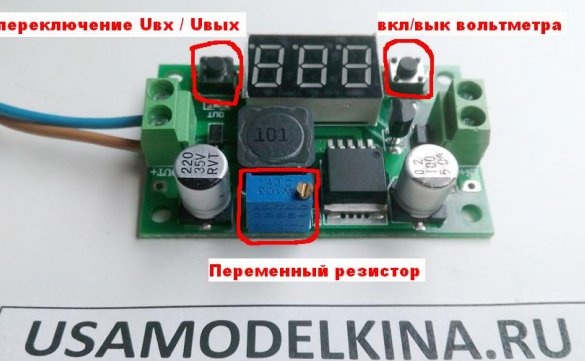
[justify] I connect the red wire of the USB cable to the IN + terminal of the pulsed DC-DC buck converter, and the black wire to the IN-terminal of the pulsed DC-DC buck converter. Now you can connect the USB cable to the Power bank and adjust the output voltage with variable resistance on the board of a pulsed DC-DC buck converter, controlling it using an LED voltmeter.
Photo 6_1
There are two buttons on the pulse DC-DC buck converter board. The button, next to which there is an IN inscription on the board, turns the LED voltmeter on and off by successively pressing it. The button, next to which there is an inscription OUT on the board, changes the readings of the input (IN) voltage and output (OUT) voltage on the LED voltmeter by successively pressing it. The corresponding LED lights up. Next to these LEDs on the board are inscribed IN and OUT.
[/ justify]Photo 7
Photo 8
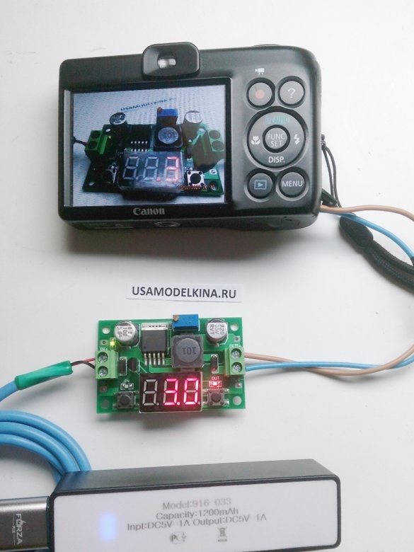
I connect the Power bank to a pulsed DC-DC buck converter. I turn on the LED voltmeter on the board of a pulsed DC-DC step-down converter and observe a voltage of 4.8V. The question arose - what voltage to set? It was solved by trial and error. I set the output voltage to 2.8 V on the board of a pulsed DC-DC buck converter. I connected the camera, I press the On button, but it does not turn on. Turned off the camera. I twisted a variable resistor, set the voltage to 2.9V. I connected the camera, I press the On button, but it does not turn on again. I turned it on at an output voltage of 3V. Took a picture, the result in the photo below.
Photo 9
Photo 10
As a result, I get a mobile camera power system with a Li-ion battery with a capacity of 1200 mAh. Now I can use my camera in the cold. The Li-ion battery will be in the clothes pocket all the time, and the camera can only be removed if necessary to take a picture.
I would like to note that on sale there are adjustable step-down power modules without an LED voltmeter on the LM2596S-ADJ chip, with an input voltage range from 4 to 40V, with an adjustable output voltage range of 1.5-35V, with a rated current of 2A. They cost two times cheaper, and they are easier of course. Power bank can be used different, with a larger capacity and with a different output voltage.
Thanks for attention!
Success in creative work!


