
Hello dear friends. In this article I want to show you how I assembled a voltage converter from 12 to 220 volts with a power of about 40 watts.
Here is a diagram of the device itself
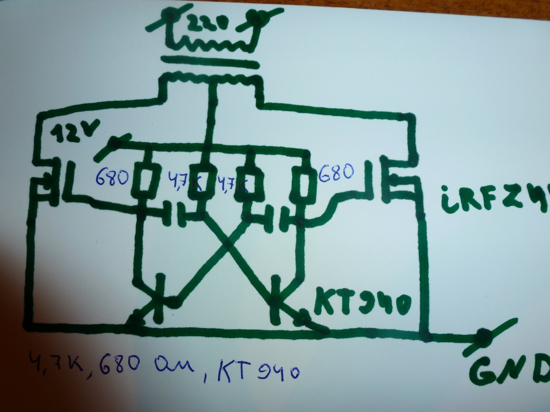
40 watts will be if the power is normal and the transistors will stand on the heatsinks. The scheme is quite simple and does not require adjustment, it has been tested by many radio amateurs.
The scheme consists of 3 parts
1 Part is a multivibrator with two bipolar transistors in my case, this KT940A can also be installed (KT819, kt315, kt815, kt817). Also in the multivibrator there are four limiting resistors, the first two at 680 ohms, the second two at 4.7 kΩ.
2 The part consists of two field keys, in my case these are powerful field workers IRFZ44N, you can also replace them with (IRF3205, IRFZ48, IRF 2505, IRFP260).
And finally, the third part is the output transformer, it can be any main thing that it has a 220 volt network winding and 12 volt winding with a tap from the middle, such a transformer can be found in an old uninterruptible system or removed from complex 5.1.
Let's move on to assembling the circuit, I started with a printed circuit board, I printed the circuit board on a laser printer on glossy photo paper.
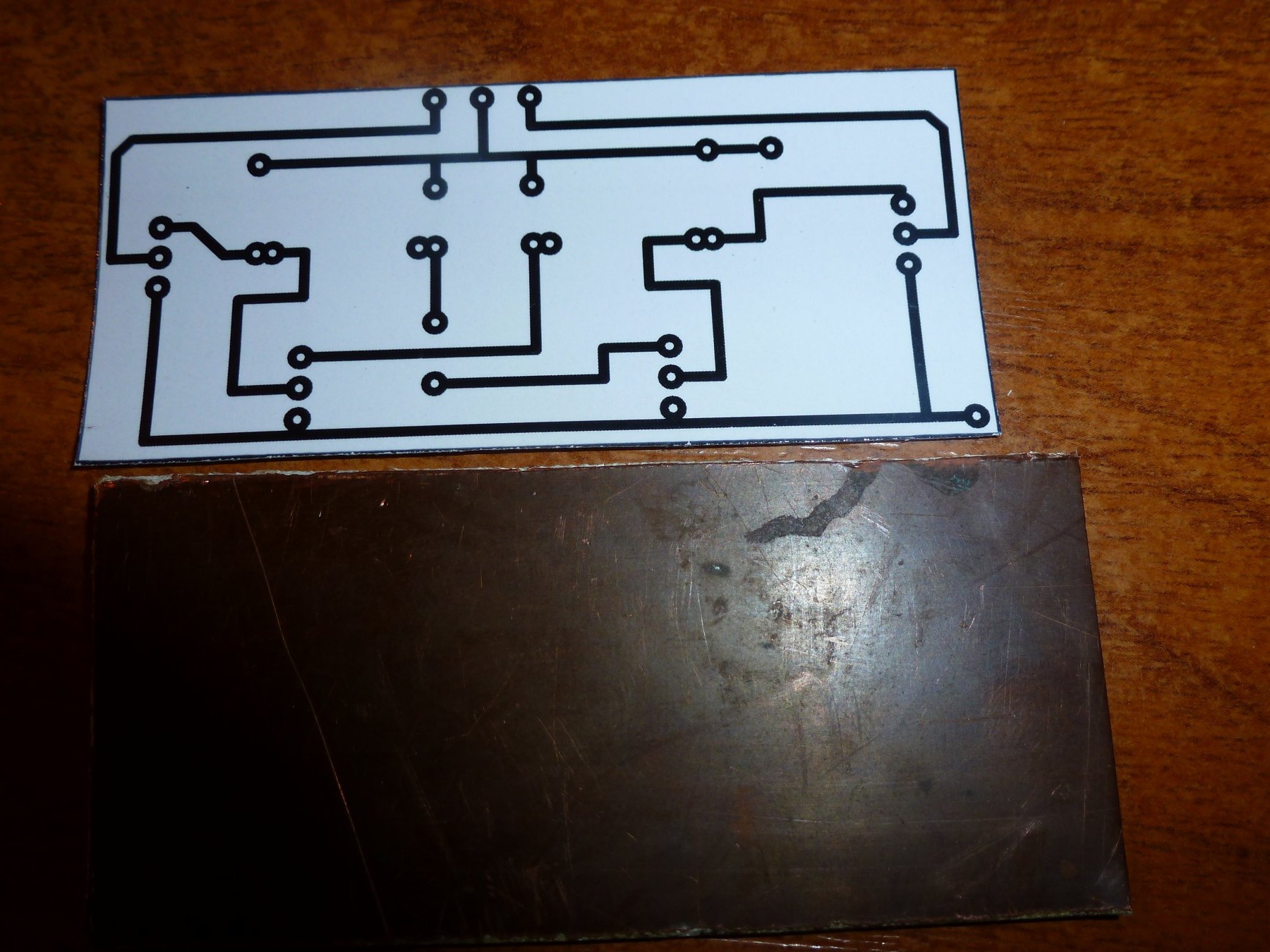
Then transferred to the board
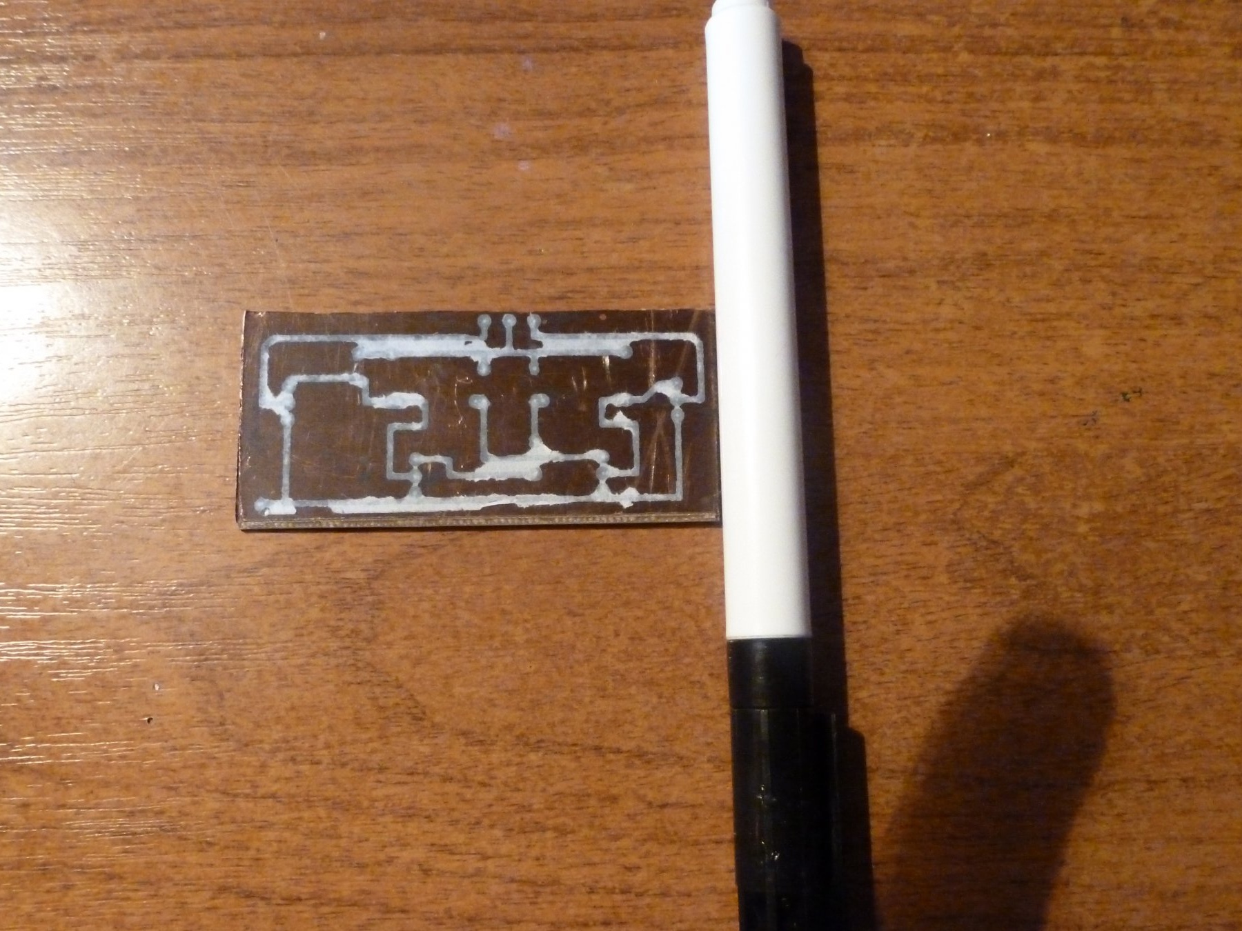
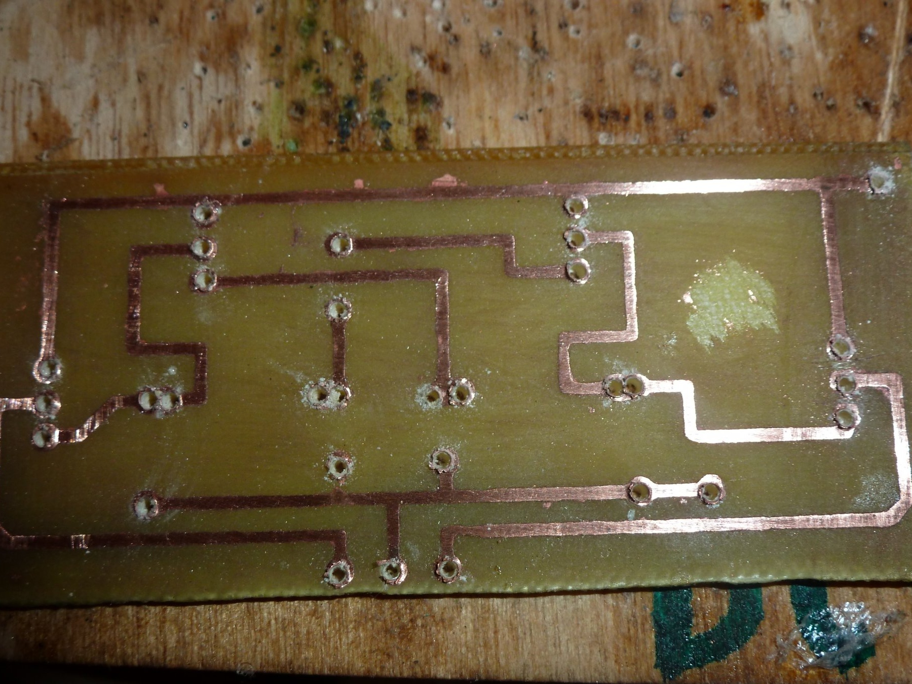
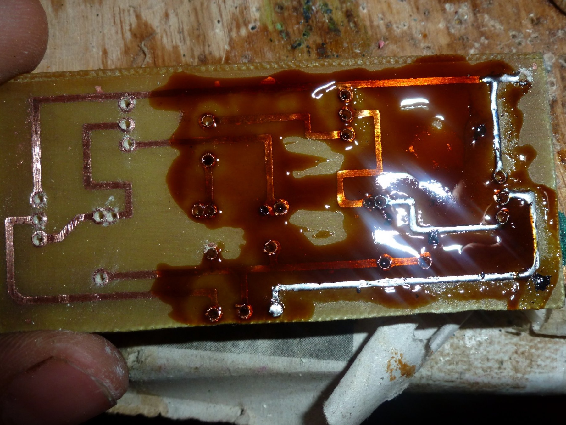
I washed off the remnants of paper with water and for one decided to draw tracks with a permanent marker, and threw it into the etching solution, I etched with hydrogen peroxide.
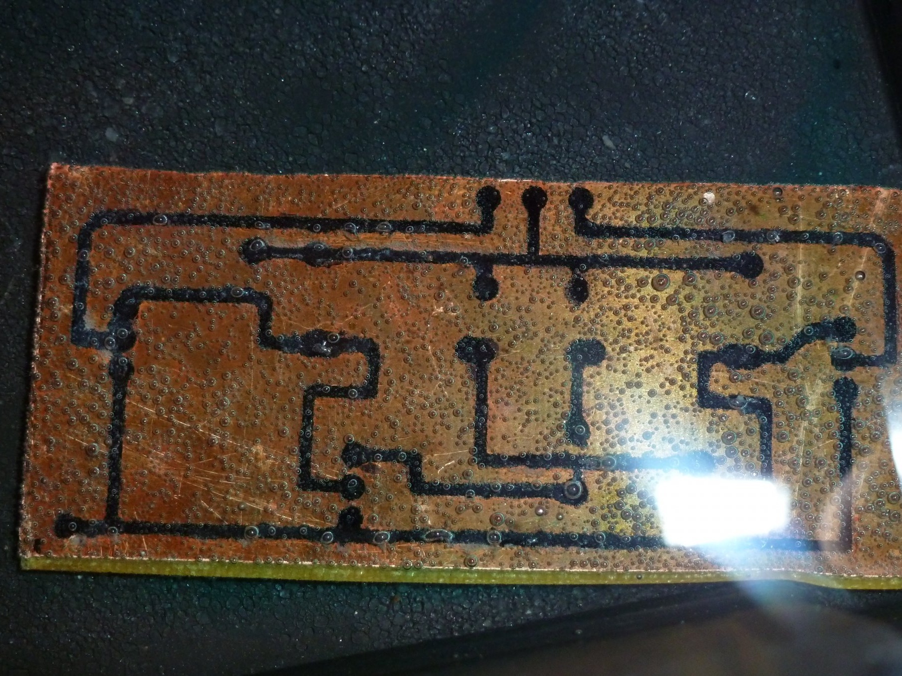
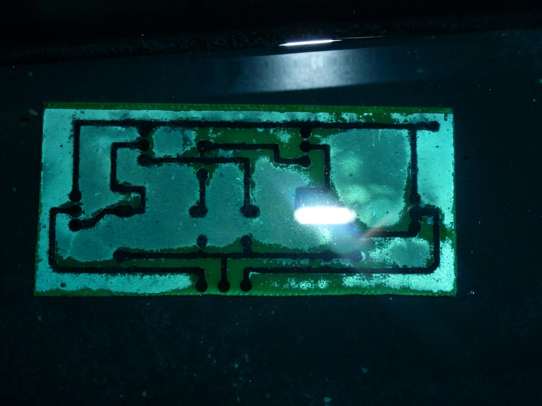
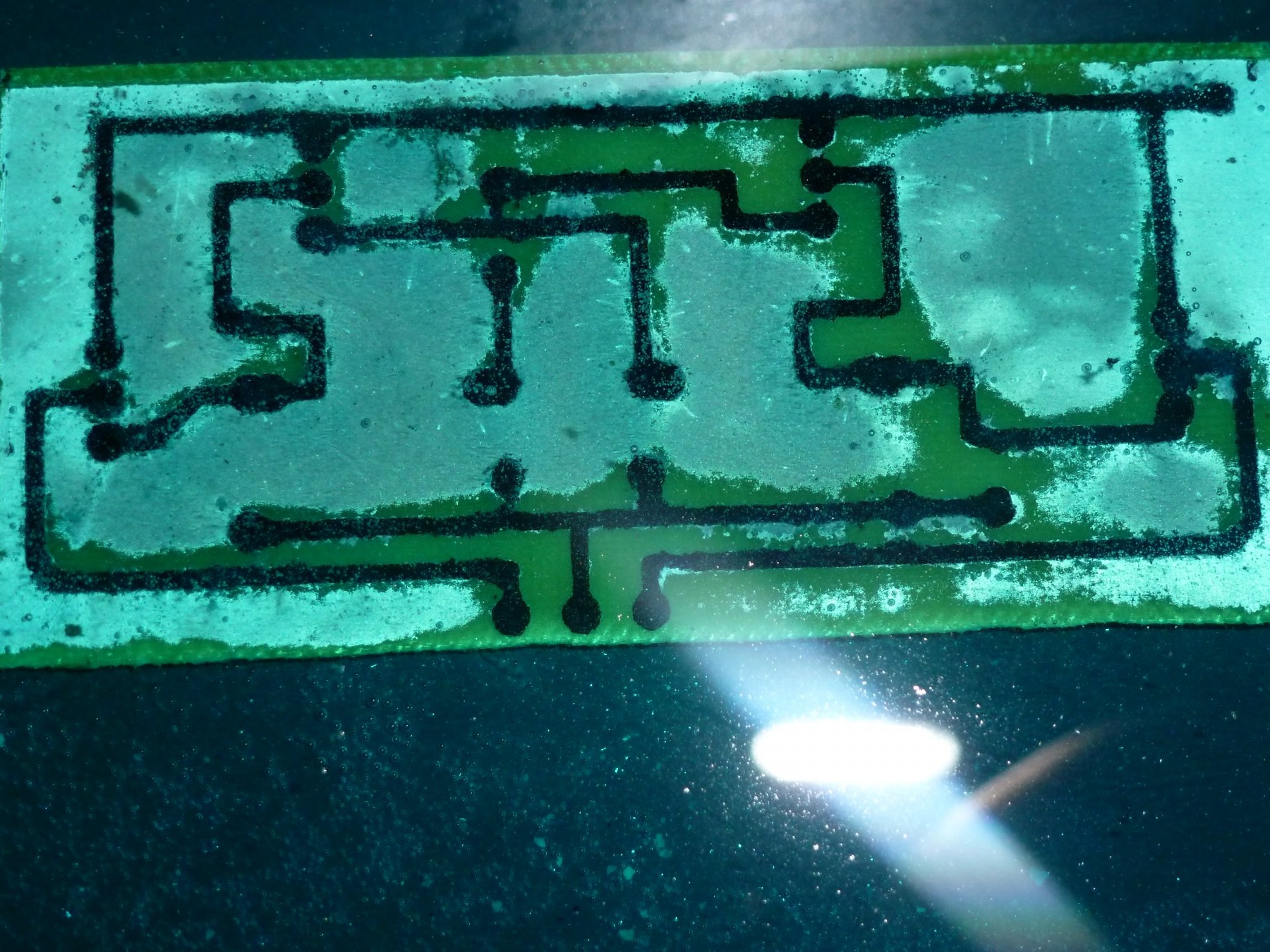
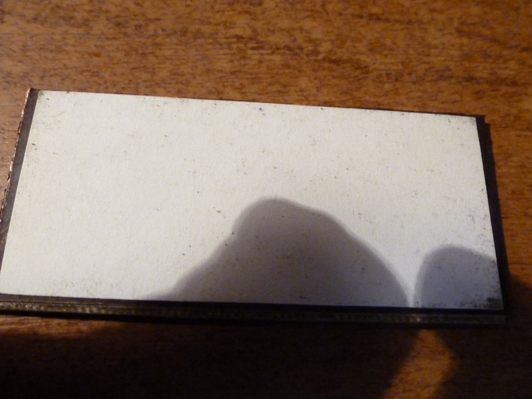
The board is etched for about 30 minutes. After etching the board, it must be thoroughly washed with water, otherwise it will be sticky. Still need to be wiped with solvent
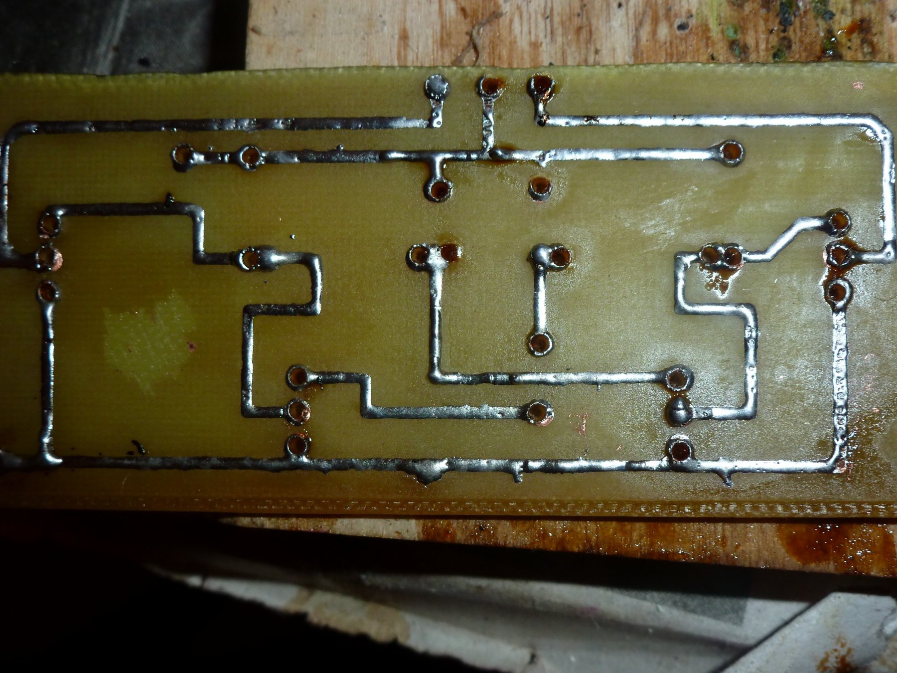
After I did this, I began to drill holes in the board.
Next is the process of tinning, the board I puddle with liquid rosin, after tinning, again, you need to wipe the flux with a solvent.
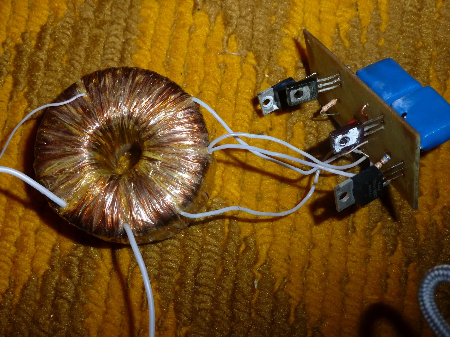
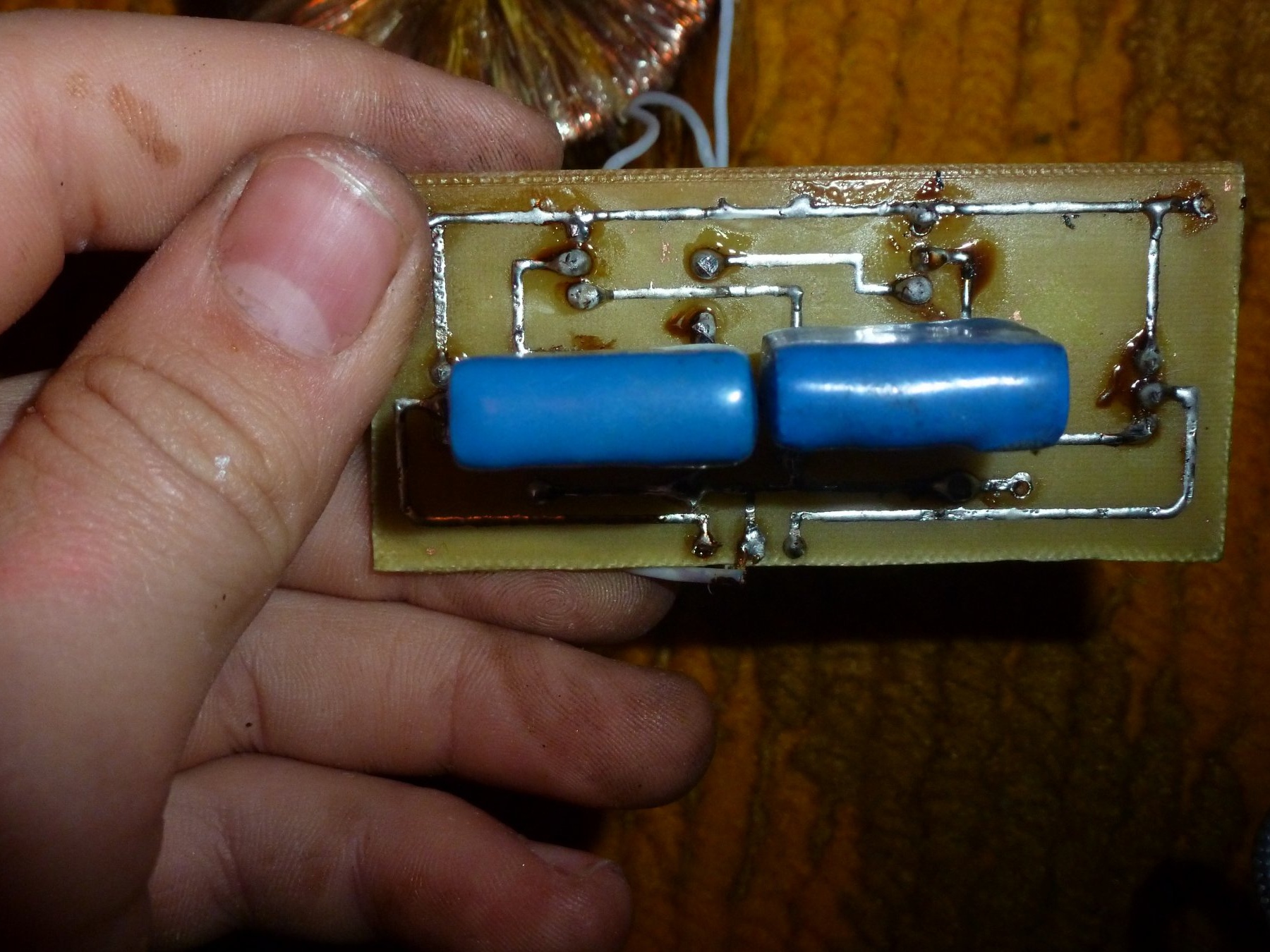
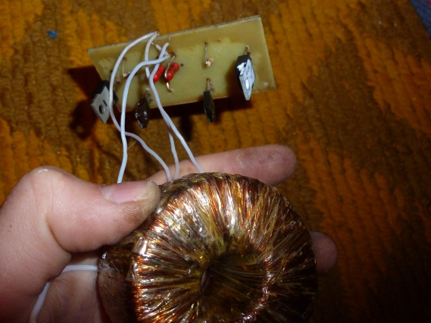
Well, then the easiest begins, you need to insert the parts into the circuit board according to the scheme. After I soldered everything, connected the output transformer, connected the power and checked the circuit for operability. See a photo of the finished device
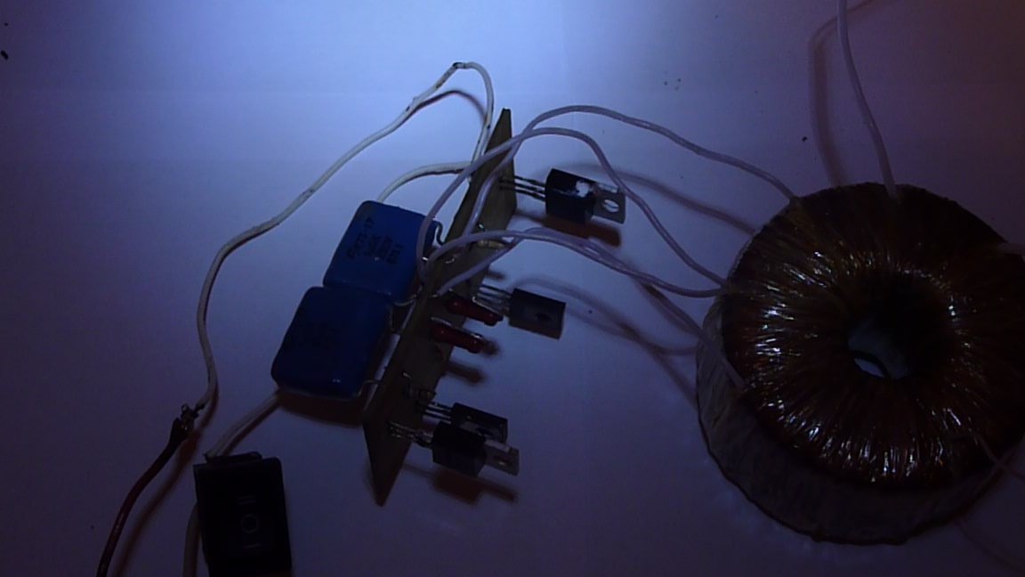
Here is another video with the work of the finished device. And even in my video the light is dimly lit because of the power supply, it is very weak with me.
Well, it seems that everything with you was DIY Electronic.