
Of course, buying an electric lighter for a gas stove today is not difficult. They are in bulk in the market, and the cost allows anyone to buy it. In this article, we will look at how you can assemble such a lighter yourself. This will be very useful, as it will let you know its principle and possibly apply it to others homemade.
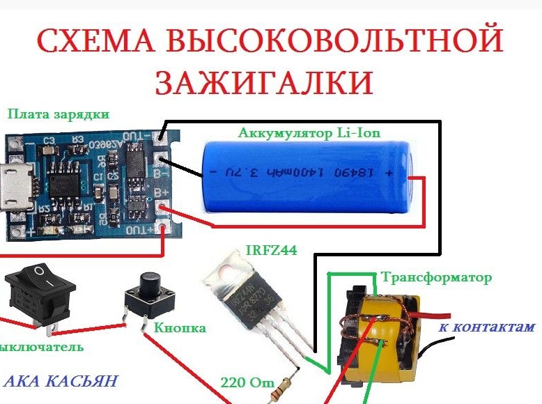
The main idea here is to obtain high voltage with a high frequency, as a result a hot spark forms between the electrodes. Such a spark can set fire to gas, cigarettes or paper. Let's consider in order how to make it.
Materials and tools for homemade:
- soldering iron with solder;
- charging for li-ion batteries;
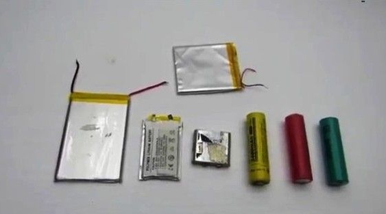
- li-ion battery (18490/1400 mAh);
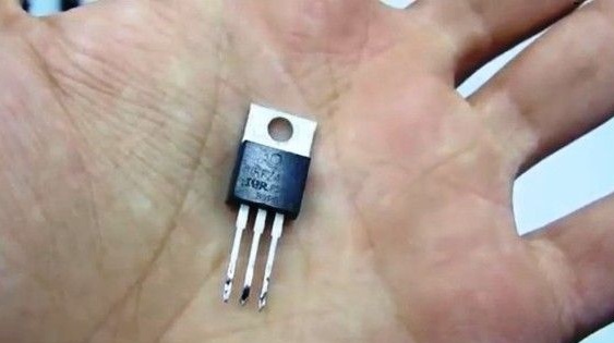
- field effect transistor IRFZ44;
- a transformer for 50 W halogen lamps (or another similar one);
- wire 0.5 mm (must be in the transformer);
- housing;
- power button and other little things.
Lighter manufacturing process:
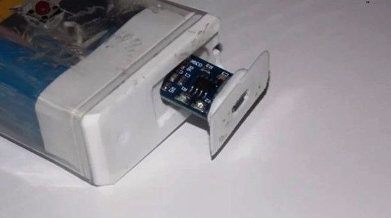
Step one. Charger preparation
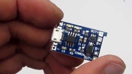
To charge a Li-ion battery, the author used a special board with protection. There are two indicators on the board, one is on when charging is in progress, and the second is on when the battery is low. Using such a device, the battery can be charged with current up to 1A through any 5V source. Alternatively, this can be done through a regular USB port.
Step Two Battery
Homemade battery fits any size and capacity. As an example, the author installed an 18490 standard battery with a capacity of 1400 mAh. Its feature is that it is somewhat shorter than the usual 18650. In general, the choice depends on the size of the lighter.
Step Three Converter
The transistor type IRFZ44, as well as a high-voltage transformer, were used as the basis for the converter. The most difficult thing to do with the transformer, it will have to wind independently.
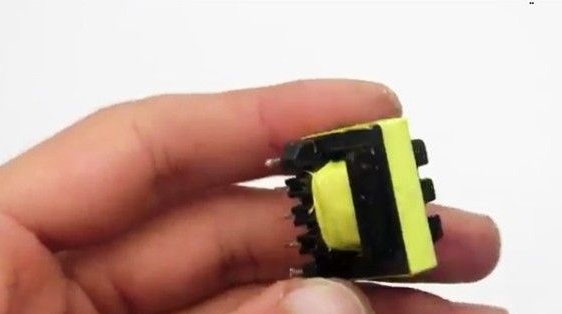
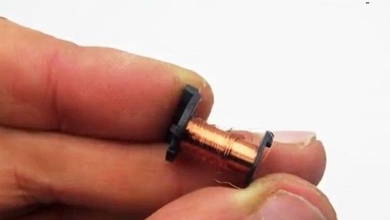
A transformer will need a core from electronic 50W halogen lamp transformer. Still for such purposes, a standby voltage transformer from a computer power supply is suitable.
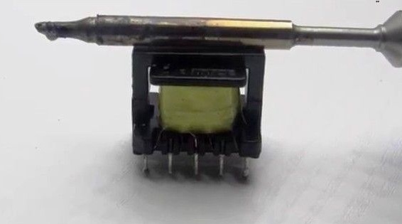
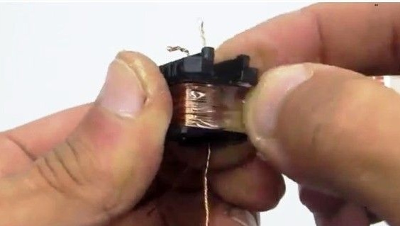
First, the transformer must be carefully soldered and the installed windings removed. Network wiring must be left, it is useful for homemade. To disconnect the halves of the transformer, they need to be heated with a soldering iron.
The primary winding has 8 turns and it has a tap from the middle. The author measures everything with a finger.
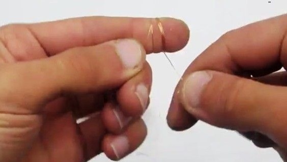
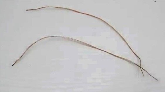
Wiring is wound with two tires, with each bus having 4 wires of 0.5 mm wire.The wire came in handy one that was as a network winding in a previously disassembled transformer.
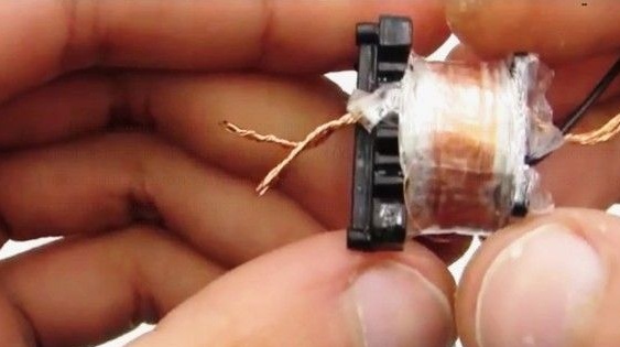
After the primary winding is wound, 10 layers of adhesive tape are wound on top for insulation. Then, from above, the author winds up a secondary or boost winding.
The secondary winding was wound with wire from a relay coil. As for the relay, any small 12-24V is suitable. The diameter of the wire should be in the range 0.08-0.1 mm.
First you need to solder a piece of stranded wire to a thin winding wire, and then start winding. The wire does not need to be cut at any stage of the winding. You need to wind it in layers, with each layer containing 70-100 turns. At the top of each layer is insulation, which is also made from adhesive tape. In conclusion, approximately 800 turns should be released.
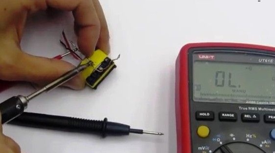
Now you can fix the halves of the core, and to the second end of the secondary winding you need to solder a piece of stranded wire. You can also ring the winding with a multimeter to check its integrity. The final insulation is insulating tape.
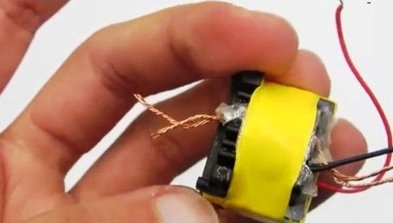
In conclusion, you need to do the phasing of the primary winding. The beginning of one shoulder connects with the end of the other. As a result, the middle point is formed, to which the plus is connected from the power source.
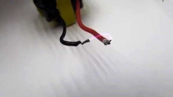
Then you can collect the oscillator circuit and check if everything works. The arc should form at a distance of 0.5 cm, and it can be stretched to 1 cm. If so, then the inverter is working correctly.
That's all, now all the details are installed in the case.
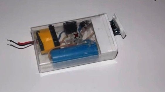
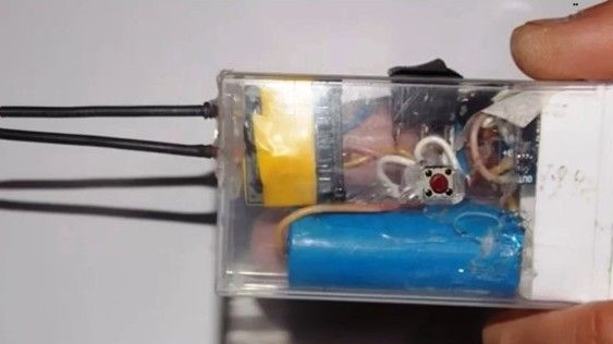
The author did not install a heat sink for the field effect transistor, but this is recommended. All exposed parts of the circuit should be hidden under heat shrinkage. That's all, after assembling the installation of the button, you can test the homemade.