


I am writing with humor, so get used to it !!! 
Okay, let's go !!!
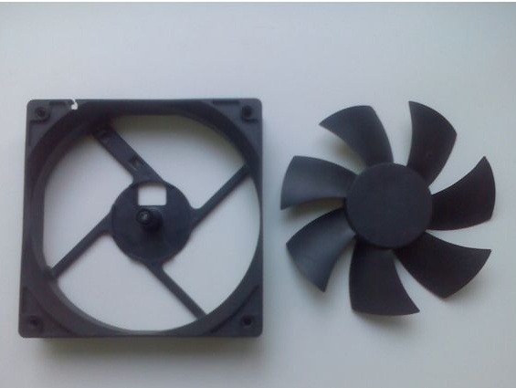
We take an old broken cooler. My size is 12x12cm
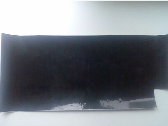
Let's start with the stand. The aesthetic appearance plays an important role in this project. Need to decorate it. To do this, you can use a self-adhesive chrome tape or blanking tape (I won’t tell you the exact name) for of furniture.
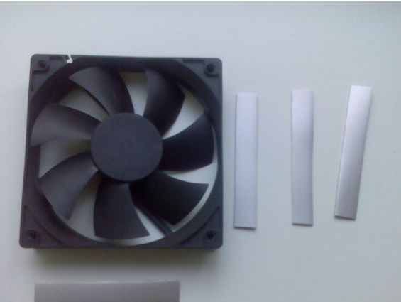
I used furniture tape. Cut into 4 even strips and glue only 3.
This is how it should turn out.
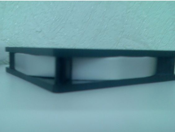
And now the answer is why only 3. At the back, we still need to drill a hole under our fan power connector.
Now glue the last 4 strip. We are waiting for it to dry and drill or break up (: (whoever has what is at hand) a hole under our connector. In principle, you can glue a strip and then drill it all together at once, but I'm not looking for easy ways
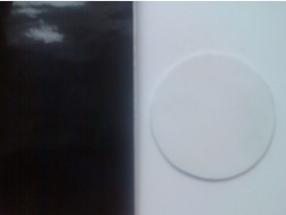
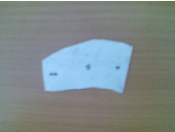
Then you have to suffer a little and cut two identical plates from plexiglass. Plexiglas thickness 2-3mm. Ie it is possible both that and another and even the third 2.5mm (:
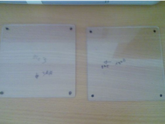
The edges should be flat and without nicks. No, no, and once again no, we don’t make hack, so let's not be lazy friend and do everything well!
Emery and a couple of files will help you here. If there is no emery, then run to the neighbor Kolka, or work with a file.
OOOO !!!! this is another matter, and I myself am pleased that at least I did something myself.
Now you have to resort to a little theft for the good of the homeland. You need to find the old type sewer pipe (gander). This will be our mast!
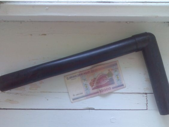
We cut our pipe to the estimated size.
I hope there is a hacksaw.
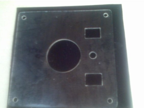
Now we take the top plate and mark our hole where the pipe will go. Simply put, hold a marker and circle the pipe.
Carefully drill a small drill over the entire radius and quietly break out unnecessary plastics. And again for the file to align all the edges.Only make the hole for the pipe off-center (as in this photo, below will be a photo where you can see that the hole is next). I already did this and it turned out ugly. I had to redo the entire fan almost anew. So move the pipe as far as possible to the back wall and naturally the hole for it.
The same for our switches (toggle switches, buttons, switches) whatever you want.
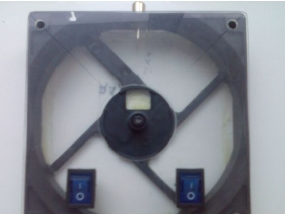
We drill, break out and insert. I liked those. When turned on, there is a light inside the switch that lights up. If you take, pay attention to the voltage. Should melt 12V. It’s just that there are exactly those on 220V.
I forgot to say, just glue the bottom plate.
Oh, and now almost the most interesting. Fun with LEDs ... ugh you, LEDs.
You have to buy 2 things of any color. LEDs should be with scattering focus. Large angle lighting. Go to the seller, he will tell you everything. But if suddenly you have directionals, there is nothing terrible here. Just rub the lens with emery cloth, and you will ruin it, thereby making a diffusing lens. It is also necessary to buy a pair of 1 kΩ resistors. After all, we will connect to 12v. If there are no resistors, then when connected, you will be happy for your backlight for a split second. : smiley:
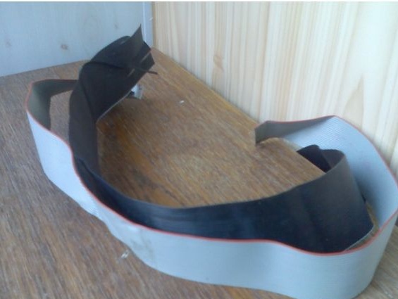
To connect the LEDs, you can use the old cable from the computer. We tear off two wires and solder them to the legs (not naturally) of the resistor and LED. It is better to twist the resistor by plus. It’s possible and minus, the scheme will work, but as it should be and the rules for plus. If someone does not understand, then you just need to twist one end of the resistor and LED. Where the LED plus will understand for yourself when a couple of pieces burn. Well, if it’s a pity, connect a 1.5 volt battery and everything will immediately become clear.
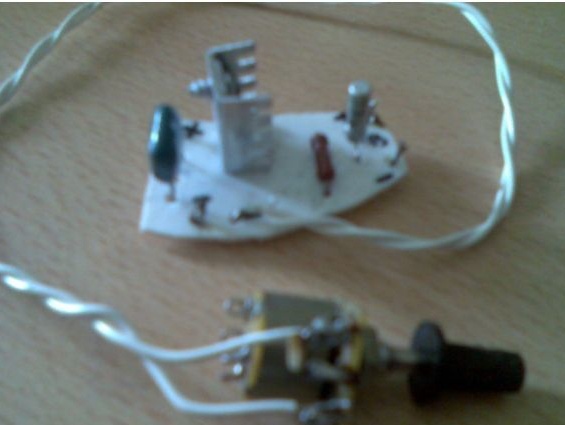
Verification was successful.
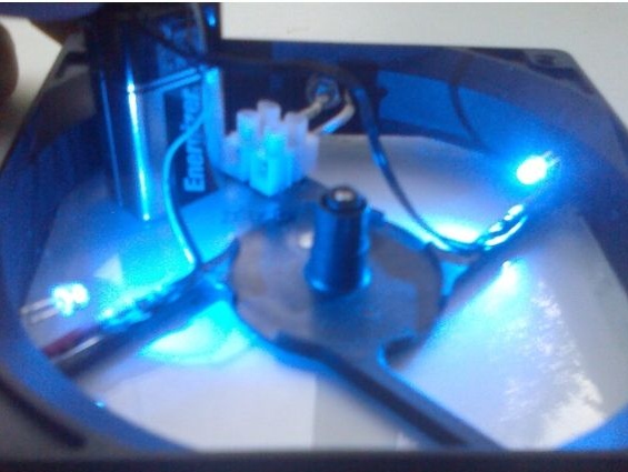
As you noticed, I also glued the terminal strip. In the future, it will come in handy. I used the power connector type "tulip". Solder the wires to the mother "tulip" and clamp the second end in the terminal block. Remembering the polarity is very easy, take two markers black and red and mark on the terminal block. Red plus. Black minus. Usually the standard connection of the connectors is a side minus, a central plus. But you can do as you want, only when connecting the circuit, MANDATORYLY COMPLY WITH POLARITY.
Next, we will have to bother any plumber and ask him for a “siphon”. Or screw down at the mother-in-law from under the sink. Here she will be glad when the dishes start to wash. But it’s more important to us, really.
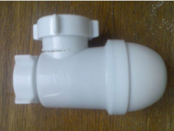
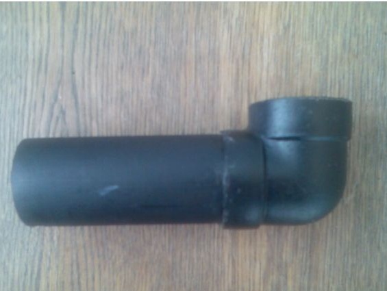
I already started to saw, and then I realized that I had not taken a picture. Saw off a ring that fits our size. What size do you ask? Yes, the shtob our pipe fit into it tightly.
Well, here is our ring !!!
That is why we have suffered so much!
The ring plays the role of the holder of our mast. And in the hole you need to connect the motor.
Well, here I could not restrain myself and once again checked the backlight. With a trembling hand he brought the power wires to the crown and about a MIRACLE, his plan came true.
Now it’s clear, you say, why it took so long to suffer from plexiglass. Yes, you probably already guessed that this is our original highlight.
I did not have time to look around already and night in the yard. I want to sleep, but there’s a lot of work. I advise you to do the following work better in the afternoon, otherwise you can ruin everything.
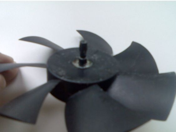
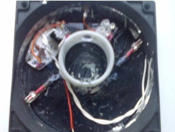
This is our motor. By the way, it ideally enters our pipe, there is really a small gap, but it’s better and it will serve us as an adjustment. We throw out a board with incomprehensible details from it. We will only lose power on them. It is only necessary to leave the brushes and, accordingly, solder the wires we need are long.
The next step is fixing the motor in the pipe.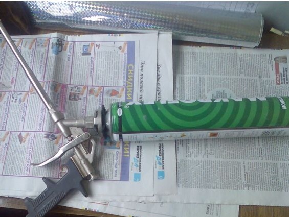
To this end, mounting foam will help us. Foam is not worth buying, since we need only one zilch. You can beg for a neighbor, or ask all relatives. In the end, someone will get angry and give you a joke on the forehead, a joke. I myself am not builder and I had to take a steam bath to find her.
Install the motor and foam the pipe.
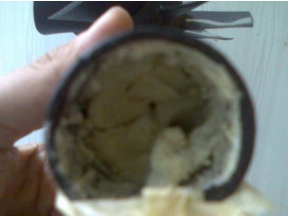
We'll have to hold the motor for about 30 minutes, so that it does not fail. Do not forget to lead the wires through the hole in the bottom of the pipe. When the foam dries, we center our motor.If something is not done right, then you have to gouge the foam, and this is just (mat). So in advance everything is checked and double-checked 10 times.
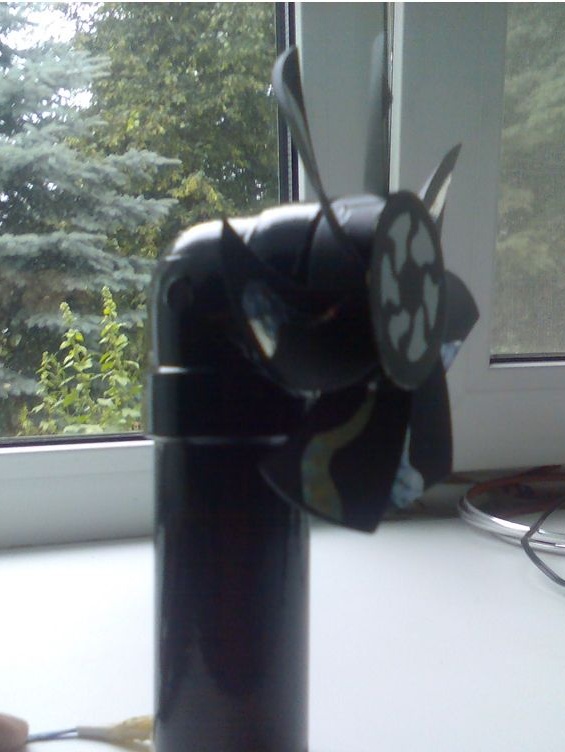
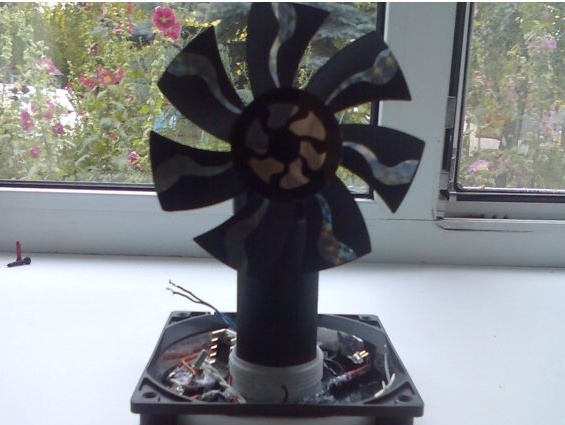
To distract from the topic, I propose to evaluate my creative mess on the window. : smiley:
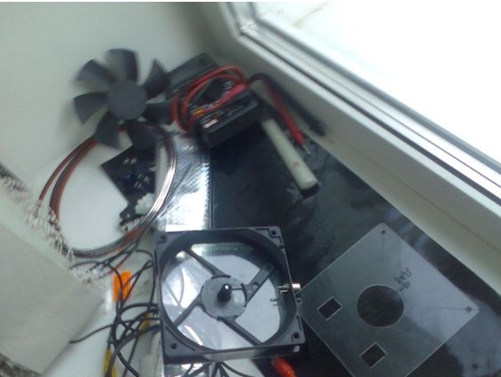
Just the soul rejoices when you see this.
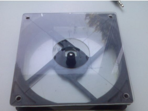
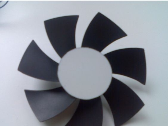
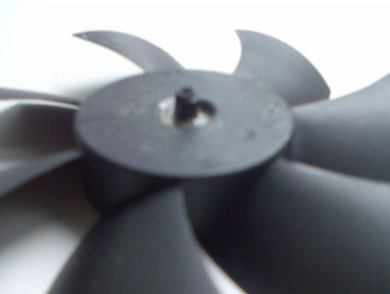
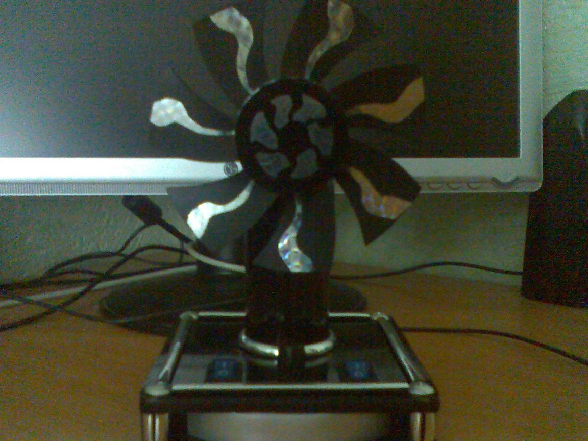
Now let's take care of the propeller itself.
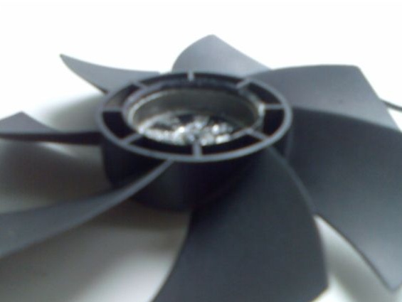
It must be turned over so that during rotation the air flow blows at you.
Since this will be the “face” of the propeller, we need to close it with something.
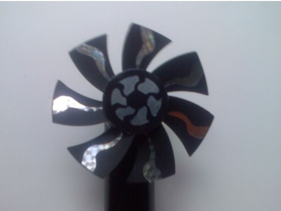
That's what it looks like when you stick it.
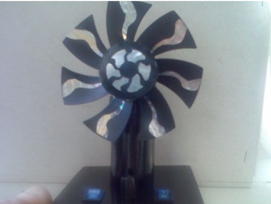
I leave the whole decoration to you, since everyone has different tastes.
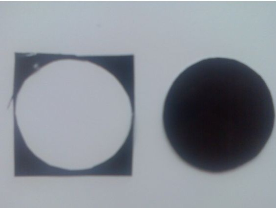
From black adhesive paper we cut out a circle and then whoever is what. You can make a radiation safety icon (remember STALKER), you can make it look like a cast disk of a car, you can make a BMW icon. In short, who wants it and does it. Just do not glue it yet, otherwise you need to mount the propeller.
Now we need to put the propeller on the motor shaft.
To do this, I drilled the back wall (and when the cooler worked, it turns out the front one) and inserted a plastic gear. Where I got it, the question immediately begs. I had to disassemble the old broken Mayak tape recorder, there is plenty of such kind of stuff, or any other. Again, my flea market and passion helped pull everything home.
We cut off the unnecessary part of the fasteners.
Each will have a different way depending on how deep the motor is inserted.
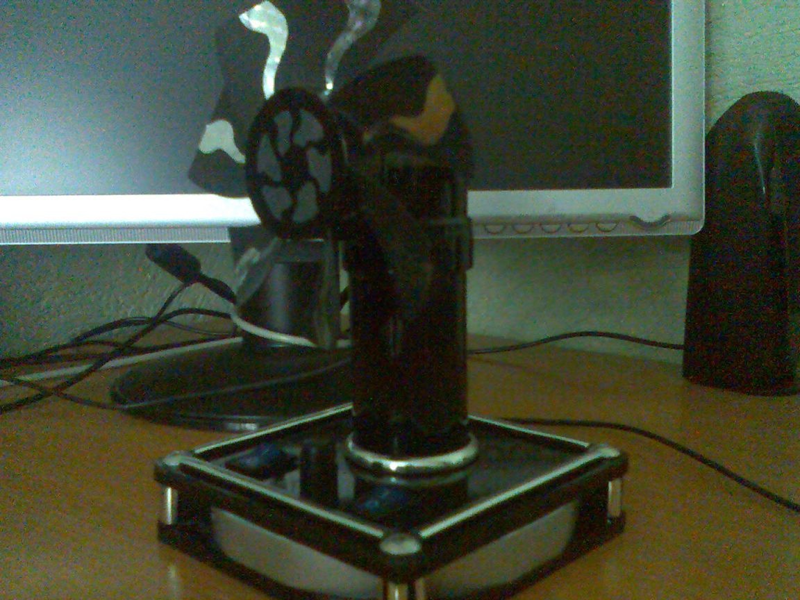
Well, here they are, I designed my fan like this.
I used adhesive paper on the blades.
We glue our pipe with black paper. Try a home hairdryer, it helps a lot when you need to bend the edges or stretch.
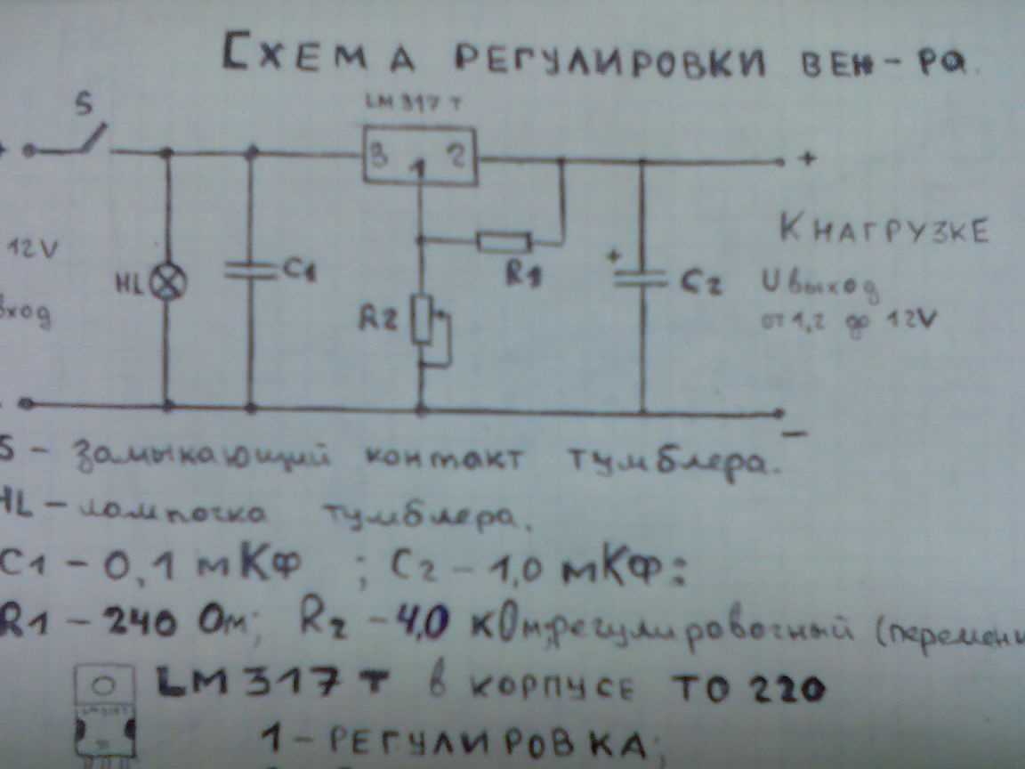
We turn to the most interesting part of the project under the title, “But do we get anything with this adjustment?” I spent many hours browsing the Internet in search of an answer to this question. I really did not find anything. At first I thought stupidly to put a variable cutter and adjust the fan speed. I tried it and I don’t want anymore, with such a connection (one variable cutter) the transformer is terribly heated, but this is not good. I went to the market and asked the guru. He immediately stuck mikruhu in my hands and says take it and do not worry. The bottom line is that we can change stresses with the help of this mikruha and a handful of details. Even kindly provided a redraw scheme. Hurrah!!! I screamed and rushed headlong home. At home, I found more information on this mikruha in nete. It turns out to be a pretty useful thing. We can adjust the voltage and thereby change the fan speed. Mikruha stands called LM 317t, I think many radio amateurs are familiar with it. Adjustment voltage from 1.2V to 40V. The nominal current is 1.5 A. What is enough with a huge margin (I'm talking about current). Well, it remains to buy, find, steal, and beg for the rest of the radio components.
If you in radio electronics are not BU-BU. I advise you to read the book "Electronics for Dummies". I want to say that with my knowledge it was still very interesting for me to read it. In any case, it doesn’t hurt. The basics there are very simple and accessible described. And this is the most important !!!
Set of the right stuff. : smiley:
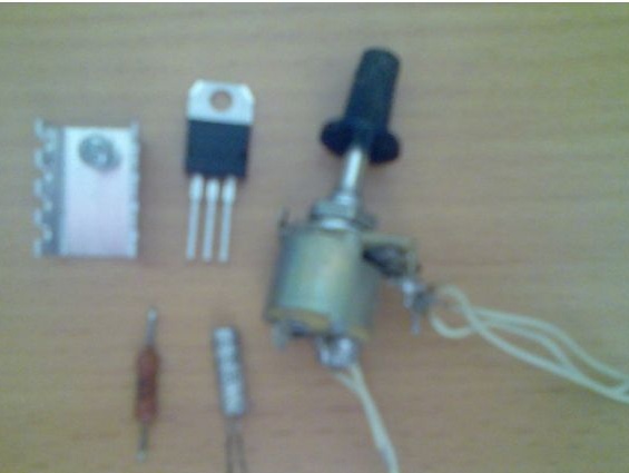
There is just no second Conder.
A piece of plastic or textolite is suitable for a board. You can etch the board, but I did not do this for one simple reason, I do not have it. And there’s no sense in such a trifle.
Well, and do not, cost plastic. The shape of the board is customized for the area on which it will stand.
Solder everything to a place and check.
A variable resistor according to the original circuit at 40v is taken 5kOhm. The same master on the market suggested that if it was 12v, then the cutter should be taken at 3.3 kOhm. I tried 4.2 3.3 2.2 kOhm almost the same. You can bet any, but you should first compare the work of all (if any).
Mikruhu is better to put on a small radiator. Although it is possible without him, it is nevertheless desirable with him.Thermal grease necessarily KTP-8. Mica padding is not needed.
When we checked everything and made sure that everything works, then boldly attach our board.
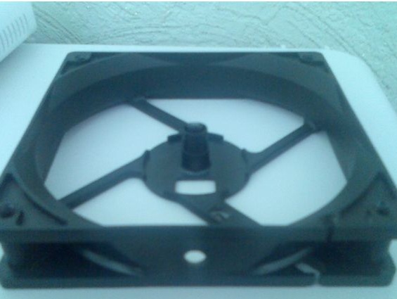
Take a close look at the ring (mast holder), this is a more recent photo and it shows that the ring is pushed to the back wall.
When everything works, we just have a little bit left.
We take our black adhesive paper and glue the front panel with a margin.
Peel off the paper and press it as it should.
With a sharp clerical knife, we cut off the remains.
Now you need to cut out under the toggle switch, a variable resistor and a pipe.
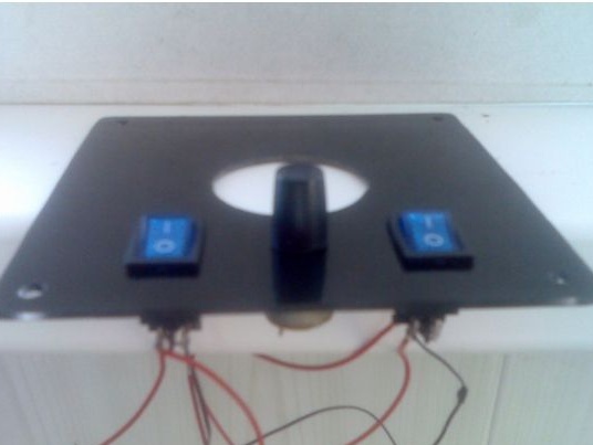
When they cut it out, then we insert all the causals.
Ah, beautiful !!!
Solder everything and fasten it, but stronger. Just do not overdo it, otherwise you can break the plexiglass. The design and decoration is entirely up to you. If I’m wondering how I did it, I simply decorated it with a thin chrome ribbon.
Here is my final and most important work result.
Now let's make a power supply for our fan. More precisely nutrition.
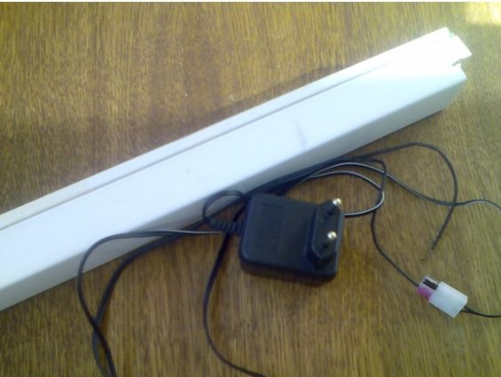
We take a piece of the installation box or the cable of the channel (as you please) and make a box out of it.
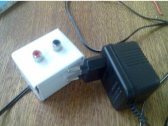
Here you are, and the power supply.
Answers to your questions:
1)Because I still plan to make a mini air conditioner and I will also power it from the unit, and it will stand on my table.
2)
Take any stabilized block on 10-12V. I took from the SEGA prefix 10V 1.2A.
3)
Because I have at home connecting laces even in salt cans, that is, a lot. That's why I decided to make on tulips. Although the shoelaces will go in favor.
As I have promised. Adjustment circuit.
SPECIFICATION
(this is how much and what you need)
• Broken cooler - 1pc (you can whole): smiley:
• Motor from a 12V tape recorder - 1 pc.
• Muffler tape furniture - 50cm.
• Terminal block for two connections - 1 pc.
• Plexiglass - measure yourself. : smiley:
• Glue - 1 tube (approximately)
• Self-tapping screws for a cross - 4pcs (beautiful).
• Connecting wires - 1km (just kidding). : smiley:
• LEDs - 2pcs (color to your taste).
• Resistors 1 kOhm - 2pcs.
• 240 Ohm resistor - 1 pc.
• 1mkF electrolyte capacitor - 1 pc.
• Capacitor (ceramic, film) 0.1uF - 1pc.
• Variable resistor - 1 pc. (From 2 to 4 kOhm).
• Microcircuit LM 317t - 1pc.
• Toggle switch with 12V backlight - 2pcs.
• PVC sewer pipe - 1 pc.
• Foam mounting - (take from a friend): smiley:
• Black self-adhesive film - width 1m, length 50 cm. (This is with a margin)
• Chrome edging (tape) - the more the better.
It seems that I have not forgotten anything. If something is not clear, I will answer.
A couple of useful tips.
• Do not look around and buy yourself an adhesive gun. A very useful thing, silicone pencils of different colors go to it. The gun costs (the cheapest) 25t. It is very suitable for those people whose fire is burning from behind, i.e. I want everything at once. The gun heats the silicone rod, and you glue it. It does not stink and freezes in 1 minute. Now you understand why I said for those who want everything at once. And in principle, it is suitable for everyone, especially for those people who like to do everything do it yourself.
• More different tools. It will be easier to work. Or you’ll have to run every 5 minutes to Kolka’s neighbor.
• Desire and desire, and most importantly perseverance must be. If you take it, then bring the matter to an end.
• Read a couple of books on electronics. As questions arise, ask and feel free to show that you do not know this.
• Well and most importantly, BELIEVE IN YOURSELF and everything will turn out.
All success in the creative industry !!!!